Also included among the plethora of OneFS 9.5 enhancements is an updated NFS lock reporting infrastructure, command set, and corresponding platform API endpoints. This new functionality includes enhanced listing and filtering options for both locks and waiters, based on NFS major version, client, LIN, path, creation time, etc. But first, some backstory…
The ubiquitous NFS protocol underwent some fundamental architectural changes between its versions 3 and 4. One of the major differences concerns the area of file locking.
NFSv4 is the most current major version of the protocol, and it natively incorporates file locking, thereby avoiding the need for any additional (and convoluted) RPC callback mechanisms, as with prior NFS versions. With NFSv4, locking is built in the main file protocol and supports new lock types, such as range locks, share reservations, and delegations/oplocks, which emulate those found in Window and SMB.
File lock state is maintained at the server under a lease-based model. A server defines a single lease period for all states held by an NFS client. If the client does not renew its lease within the defined period, all state associated with the client’s lease may be released by the server. If released, the client may either explicitly renew its lease, or simply issue a read request, or other associated operation. Additionally, with NFSv4, a client can elect whether to lock the entire file, or a byte range within a file.
In contrast to NFSv4, the NFSv3 protocol is stateless and does not natively support file locking. Instead, the ancillary NLM (Network Lock Manager) protocol supplies the locking layer. Because file locking is inherently stateful, NLM itself is considered stateful. For example, when an NFSv3 filesystem mounted on an NFS client receives a request to lock a file, instead of an NFS remote procedure call, it generates an NLM remote procedure call.
The NLM protocol itself consists of remote procedure calls that emulate the standard UNIX file control (fcntl) arguments and outputs. Because a process blocks waiting for a lock that conflicts with another lock holder, also known as a ‘blocking lock’, the NLM protocol has the notion of callbacks, from the file server to the NLM client to notify that a lock is available. As such, the NLM client sometimes acts as an RPC server in order to receive delayed results from lock calls.
| Attribute |
NFSv3 |
NFSv4 |
| State |
Stateless – A client does not technically establish a new session if it has the correct information to ask for files and so on. This allows for simple failover between OneFS nodes using dynamic IP pools |
Stateful – NFSv4 uses sessions in order to handle communication, as such both client and server must track session state to continue communicating. |
| Presentation |
User and Group info is presented numerically – Client and Server communicate user information by numeric identifiers, allowing the same user to appear as different names between client and server. |
User and Group info is presented as strings – Both the client and server must resolve the names of the numeric information stored. The server must lookup names to present, while the client must remap those to numbers on its end |
| Locking |
File Locking is out of band – uses NLM to perform locks. This requires the client to respond to RPC messages from the server to confirm locks have been granted, etc. |
File Locking is in band – No longer users a separate protocol for file locking, instead making it a type of call that is usually compounded with OPENs, CREATES, or WRITES |
| Transport |
Can run over TCP or UDP – This version of the protocol can run over UDP instead of TCP, leaving handling of loss and retransmission to the software instead of the operating system. We always recommend using TCP. |
Only supports TCP – Version 4 of NFS has left loss and retransmission up to the underlying operating system.
Can batch a series of calls in a single packet, allowing the server to process all of them and reply at the end. This is used to reduce the number of calls involved in common operations. |
Since NFSv3 is stateless it requires more complexity to recover from failures such as client and server outages and network partitions. If an NLM server crashes, NLM clients that are holding locks must reestablish them on the server when it restarts. The NLM protocol deals with this by having the status monitor on the server send a notification message to the status monitor of each NLM client that was holding locks. The initial period after a server restart is known as the grace period, during which only requests to reestablish locks are granted. Thus, clients that reestablish locks during the grace period are guaranteed to not lose their locks.
When an NLM client crashes, ideally any locks it was holding at the time are removed from the pertinent NLM server(s). The NLM protocol handles this by having the status monitor on the client send a message to each server’s status monitor once the client reboots. The client reboot indication informs the server that the client no longer requires its locks. However, if the client crashes and fails to reboot, the client’s locks will persist indefinitely. This is undesirable for two primary reasons: Resources are indefinitely leaked. Eventually another client will want to get a conflicting lock on at least one of the files the crashed client had locked and, as a result, the other client is postponed indefinitely.
Therefore, having NFS server utilities to swiftly and accurately report on lock and waiter status, and utilities to clear NFS lock waiters is highly desirable for administrators – particularly on clustered storage architectures.
Prior to OneFS 9.5, the old NFS locking CLI commands were somewhat inefficient and also showed other advisory domain locks, which rendered the output somewhat confusing. The following table shows the new CLI commands (and corresponding handlers), which replace the older NLM syntax.
| Type / Command set |
OneFS 9.4 and earlier |
OneFS 9.5 |
| Locks |
isi nfs nlm locks |
isi nfs locks |
| Sessions |
isi nfs nlm sessions |
isi nfs nlm sessions |
| Waiters |
isi nfs nlm locks waiters |
isi nfs locks waiters |
In OneFS 9.5 and later, the old API handlers will still exist to avoid breaking existing scripts and automation, but the CLI command syntax is deprecated and will no longer work.
Also be aware that the ‘isi_classic nfs locks and waiters’ CLI commands have also been disabled in OneFS 9.5. Attempts to run these will yield the following warning message:
# isi_classic nfs locks

This command has been disabled. Please use 'isi nfs' for this functionality.
The new ‘isi nfs locks’ CLI command output includes the following locks object fields:
| Field |
Description |
| Client |
The client host name, Frequently Qualified Domain Name, or IP |
| Client_ID |
The client ID (internally generated) |
| Created |
The UNIX Epoch time that the lock was created |
| ID |
The lock ID (Id necessary for platform API sorting, not shown in CLI output) |
| LIN |
The logical inode number (LIN) of the locked resource |
| Lock_type |
The type of lock (shared, exclusive, none) |
| Path |
Path of locked file |
| Range |
The byte range within the file that is locked |
| Version |
The NFS major version: v3, or v4 |
Note that the ISI_NFS_PRIV RBAC privilege is required in order to view the NFS locks or waiters via the CLI or PAPI. In addition to ‘root’, the cluster’s ‘SystemAdmin’ and ‘SecurityAdmin’ roles contain this privilege by default.
Additionally, the new locks CLI command sets ha a default timeout of 60 seconds. If the cluster is very large, the timeout may need to be increased for the CLI command. For example:
# isi –timeout <timeout value> nfs locks list
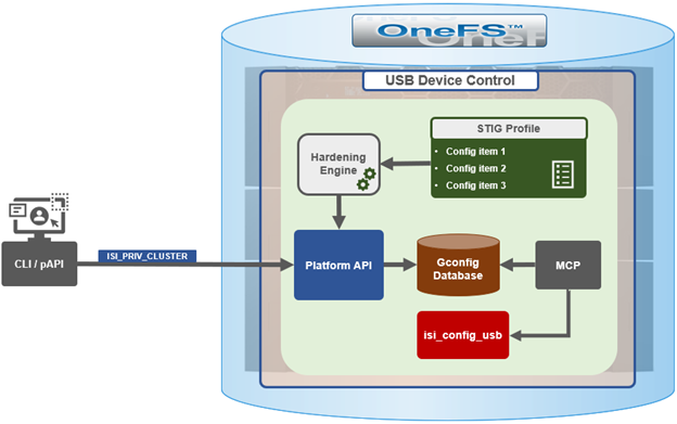
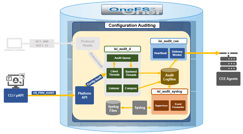
The basic architecture behind the enhanced NFS locks reporting framework is as follows:
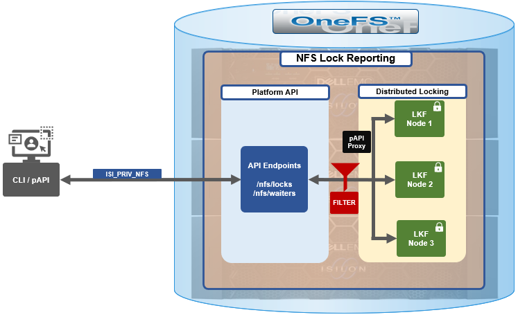
The new API handlers leverage the platform API proxy, yielding increased performance over the legacy handlers. Additionally, updated syscalls have been implemented to facilitate filtering by NFS service and major version.
Since NFSv3 is stateless, the cluster does not know when a client has lost its state unless it reconnects. For maximum safety, the OneFS locking framework (lk) holds locks forever. The ‘isi nfs nlm sessions’ CLI command allows administrators to manually free NFSv3 locks in such cases, and this command remains available in OneFS 9.5 as well as prior versions. NFSv3 locks may also be leaked on delete, since a valid inode is required for lock operations. As such, lkf has a lock reaper which periodically checks for locks associated with deleted files.
In OneFS 9.5 and later, current NFS locks can be viewed with the new ‘isi nfs locks list’ command. This command set also provides a variety of options to limit and format the display output. In its basic form, this command generates a basic list of client IP address and the path. For example:
# isi nfs locks list

Client                              Path

-------------------------------------------------------------------

1/TMECLI1:487722/10.22.10.250       /ifs/locks/nfsv3/10.22.10.250_1

1/TMECLI1:487722/10.22.10.250       /ifs/locks/nfsv3/10.22.10.250_2

Linux NFSv4.0 TMECLI1:487722/10.22.10.250       /ifs/locks/nfsv4/10.22.10.250_1

Linux NFSv4.0 TMECLI1:487722/10.22.10.250       /ifs/locks/nfsv4/10.22.10.250_2

-------------------------------------------------------------------
Total: 4
To include more information, the ‘-v’ flag can be used to generate a verbose locks listing:
 # isi nfs locks list -v

Client: 1/TMECLI1:487722/10.22.10.250

Client ID: 487722351064074

LIN: 4295164422

Path: /ifs/locks/nfsv3/10.22.10.250_1

Lock Type: exclusive

Range: 0, 92233772036854775807

Created: 2023-08-18T08:03:52

Version: v3

---------------------------------------------------------------

Client: 1/TMECLI1:487722/10.22.10.250

Client ID: 5175867327774721

LIN: 42950335042

Path: /ifs/locks/nfsv3/10.22.10.250_1

Lock Type: exclusive

Range: 0, 92233772036854775807

Created: 2023-08-18T08:10:31

Version: v3

---------------------------------------------------------------

Client: Linux NFSv4.0 TMECLI1:487722/10.22.10.250

Client ID: 487722351064074

LIN: 429516442

Path: /ifs/locks/nfsv3/10.22.10.250_1

Lock Type: exclusive

Range: 0, 92233772036854775807

Created: 2023-08-18T08:19:48

Version: v4

---------------------------------------------------------------

Client: Linux NFSv4.0 TMECLI1:487722/10.22.10.250

Client ID: 487722351064074

LIN: 4295426674

Path: /ifs/locks/nfsv3/10.22.10.250_2

Lock Type: exclusive

Range: 0, 92233772036854775807

Created: 2023-08-18T08:17:02

Version: v4

---------------------------------------------------------------

Total: 4
The above syntax returns more detailed information for each lock, including client ID, LIN, path, lock type, range, created date, and NFS version.
The lock listings can also be filtered by client or client-id. Note that the –client option must be the full name in quotes.
# isi nfs locks list --client="full_name_of_client/IP_address" -v
For example:
# isi nfs locks list --client="1/TMECLI1:487722/10.22.10.250" -v

Client: 1/TMECLI1:487722/10.22.10.250

Client ID: 5175867327774721

LIN: 42950335042

Path: /ifs/locks/nfsv3/10.22.10.250_1

Lock Type: exclusive

Range: 0, 92233772036854775807

Created: 2023-08-18T08:10:31

Version: v3
Additionally, be aware that the CLI does not support partial names, so the full name of the client must be specified.
Filtering by NFS version can be helpful when attempting to narrow down which client has a lock. For example, to show just the NFSv3 locks:
# isi nfs locks list --version=v3

Client                              Path

-------------------------------------------------------------------

1/TMECLI1:487722/10.22.10.250       /ifs/locks/nfsv3/10.22.10.250_1

1/TMECLI1:487722/10.22.10.250       /ifs/locks/nfsv3/10.22.10.250_2

-------------------------------------------------------------------

Total: 2
Note that the ‘–-version’ flag supports both ‘v3’ and ‘nlm’ as arguments, and will return the same v3 output in either case. For example:
# isi nfs locks list --version=nlm

Client                              Path

-------------------------------------------------------------------

1/TMECLI1:487722/10.22.10.250       /ifs/locks/nfsv3/10.22.10.250_1

1/TMECLI1:487722/10.22.10.250       /ifs/locks/nfsv3/10.22.10.250_2

-------------------------------------------------------------------

Total: 2
Filtering by LIN or path is also supported. For example:
# isi nfs locks list --lin=42950335042 -v

Client: 1/TMECLI1:487722/10.22.10.250

Client ID: 5175867327774721

LIN: 42950335042

Path: /ifs/locks/nfsv3/10.22.10.250_1

Lock Type: exclusive

Range: 0, 92233772036854775807

Created: 2023-08-18T08:10:31

Version: v3
Or by path:
# isi nfs locks list --path=/ifs/locks/nfsv3/10.22.10.250_2

 -v

Client: Linux NFSv4.0 TMECLI1:487722/10.22.10.250

Client ID: 487722351064074

LIN: 4295426674

Path: /ifs/locks/nfsv3/10.22.10.250_2

Lock Type: exclusive

Range: 0, 92233772036854775807

Created: 2023-08-18T08:17:02

Version: v4
Be aware that the full path must be specified, starting with /ifs. There is no partial matching or substitution for paths in this command set.
Filtering can also be performed by creation time, for example:
# isi nfs locks list --created=2023-08-17T09:30:00 -v
Note that, when filtering by ‘created’ the output will include all locks that were created before or at the time provided.
The ‘—limits’ argument can be used curtail the number of results returned, and ‘limits’ can be used in conjunction with all other query options. For example, to limit the output of the NFSv4 locks listing to one lock:
# isi nfs locks list -–version=v4 --limit=1
Note that ‘limit’ can be used with the range of query types.
The filter options are mutually exclusive with the exception of ‘version’, and ‘version’ can be used with any of the other filter options. For example, filtering by both ‘created’ and ‘version’:
This can be helpful when troubleshooting and trying to narrow down results.
In addition to locks, OneFS 9.5 also provides the ‘isi nfs locks waiters’ CLI command set. Note that ‘waiters’ are specific to NFSv3 clients, and the CLI reports any v3 locks that are pending and not yet granted.
Since NFSv3 is stateless, a cluster does not know when a client has lost its state unless it reconnects. For maximum safety, lk holds locks forever. The isi nfs nlm command allows administrators to manually free locks in such cases. Locks may also be leaked on delete, since a valid inode is required for lock operations. Thus lkf has a lock reaper which periodically checks for locks associated with deleted files
# isi nfs locks waiters
The ‘waiters’ CLI syntax uses a similar range of query arguments as the ‘isi nfs locks list’ command set.
In addition to the CLI, the platform API can also be used to query both NFS locks and NFSv3 waiters. For example, using ‘curl’ to view the waiters via the OneFS pAPI:
# curl -k -u <username>:<passwd> https://localhost:8080/platform/protocols/nfs/waiters”

{

“total” : 2,

“waiters”;

}

{

“client” : “1/TMECLI1487722/10.22.10.250”,

“client_id” : “4894369235106074”,

“created” : “1668146840”,

“id” : “1 1YUIAEIHVDGghSCHGRFHTiytr3u243567klj212-MANJKJHTTy1u23434yui-ouih23ui4yusdftyuySTDGJSDHVHGDRFhgfu234447g4bZHXhiuhsdm”,

“lin” : “4295164422”,

“lock_type” : “exclusive”

“path” : “/ifs/locks/nfsv3/10.22.10.250_1”

“range” : [0, 92233772036854775807 ],

“version” : “v3”

}

},

“total” : 1

}
Similarly, using the platform API to show locks, filtered by client ID:
# curl -k -u <username>:<passwd> “https://<address>:8080/platform/protocols/nfs/locks?client=<client_ID>”
For example:
# curl -k -u <username>:<passwd> “https://localhost:8080/platform/protocols/nfs/locks?client=1/TMECLI1487722/10.22.10.250”

{

“locks”;

}

{

“client” : “1/TMECLI1487722/10.22.10.250”,

“client_id” : “487722351064074”,

“created” : “1668146840”,

“id” : “1 1YUIAEIHVDGghSCHGRFHTiytr3u243567FCUJHBKD34NMDagNLKYGHKHGKjhklj212-MANJKJHTTy1u23434yui-ouih23ui4yusdftyuySTDGJSDHVHGDRFhgfu234447g4bZHXhiuhsdm”,

“lin” : “4295164422”,

“lock_type” : “exclusive”

“path” : “/ifs/locks/nfsv3/10.22.10.250_1”

“range” : [0, 92233772036854775807 ],

“version” : “v3”

}

},

“Total” : 1

}
Note that, as with the CLI, the platform API does not support partial name matches, so the full name of the client must be specified.