OneFS Metadata Overview

OneFS uses two principal data structures to enable information about each object, or metadata, within the file system to be searched, managed and stored efficiently and reliably. These structures are:

  • Inodes
  • B-trees

OneFS uses inodes to store file attributes and pointers to file data locations on disk, and each file, directory, link, etc, is represented by an inode.

Within OneFS, inodes come in two sizes – either 512B or 8KB. The size that OneFS uses is determined primarily by the physical and logical block formatting of the drives in a diskpool..

All OneFS inodes have both static and dynamic sections.  The static section space is limited and valuable since it can be accessed in a single I/O, and does not require a distributed lock to access. It holds fixed-width, commonly used attributes like POSIX mode bits, owner, and size.

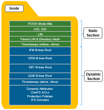
In contrast, the dynamic portion of an inode allows new attributes to be added, if necessary, without requiring an inode format update. This can be done by simply adding a new type value with code to serialize and de-serialize it. Dynamic attributes are stored in the stream-style type-length-value (TLV) format, and include protection policies, OneFS ACLs, embedded b-tree roots, domain membership info, etc.

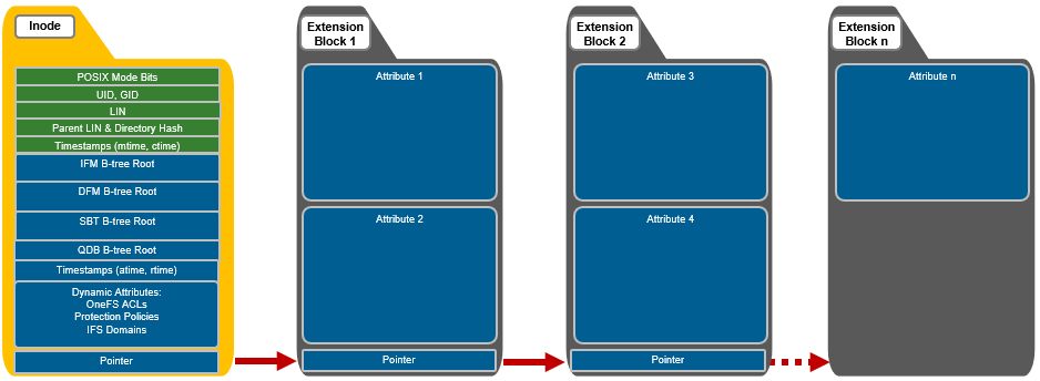
If necessary, OneFS can also use extension blocks, which are 8KB blocks, to store any attributes that cannot fully fit into the inode itself. Additionally, OneFS data services such as SnapshotIQ also commonly leverage inode extension blocks.

Inodes are dynamically created and stored in locations across all the cluster’s drives, and OneFS uses  b-trees (actually B+ trees) for their indexing and rapid retrieval. The general structure of a OneFS b-tree includes a top-level block, known as the ‘root’. B-tree blocks which reference other b-trees are referred to as ‘inner blocks’, and the last blocks at the end of the tree are called ‘leaf blocks’.

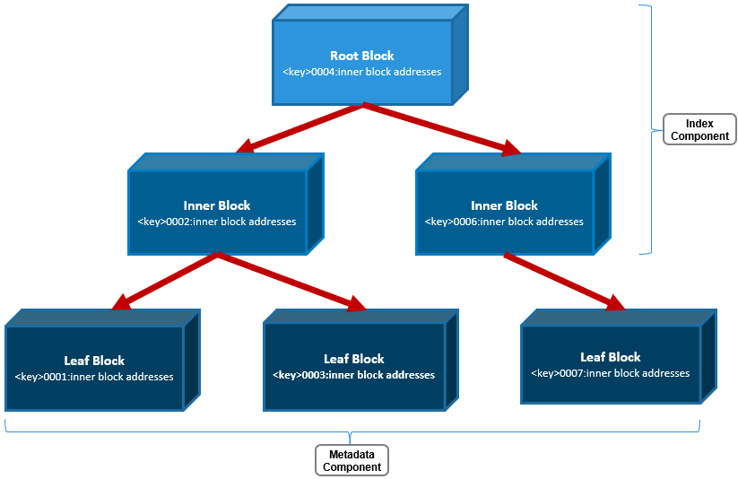
Only the leaf blocks actually contain metadata, whereas the root and inner blocks provide a balanced index of addresses allowing rapid identification of and access to the leaf blocks and their metadata.

A LIN, or logical inode, is accessed every time a file, directory, or b-tree is accessed.  The function of the LIN Tree is to store the mapping between a unique LIN number and it’s inode mirror addresses.

The LIN is represented as a 64-bit hexadecimal number.  Each file is assigned a single LIN and, since LINs are never reused, it is unique for the cluster’s lifespan.  For example, the file /ifs/data/test/file1 has the following LIN:

# isi get -D /ifs/data/test/f1 | grep LIN:

*  LIN:                1:2d29:4204

Similarly, its parent directory, /ifs/data/test, has:

# isi get -D /ifs/data/test | grep LIN:

*  LIN:                1:0353:bb59

*  LIN:                1:0009:0004

*  LIN:                1:2d29:4204

The file above’s LIN tree entry includes the mapping between the LIN and its three mirrored inode disk addresses.

# isi get -D /ifs/data/test/f1 | grep "inode"

* IFS inode: [ 92,14,524557565440:512, 93,19,399535074304:512, 95,19,610321964032:512 ]

Taking the first of these inode addresses, 92,14,524557565440:512, the following can be inferred, reading from left to right:

  • It’s on node 92.
  • Stored on drive lnum 14.
  • At block address 524557565440.
  • And is a 512byte inode.

The file’s parent LIN can also be easily determined:

# isi get -D /ifs/data/test/f1 | grep -i "Parent Lin"

*  Parent Lin          1:0353:bb59

In addition to the LIN tree, OneFS also uses b-trees to support file and directory access, plus the management of several other data services. That said, the three principal b-trees that OneFS employs are:

Category B+ Tree Name Description
Files Metatree or Inode Format Manager (IFM B-tree) •       This B-tree stores a mapping of Logical Block Number (LBN) to protection group

•       It is responsible to storing the physical location of file blocks on disk.

Directories Directory Format Manager (DFM B-tree) •       This B-tree stores directory entries (File names and directory/sub-directories)

•       It includes the full /ifs namespace  and everything under it.

System System B-tree (SBT) •       Standardized B+ Tree implementation to store records for OneFS internal use, typically related to a particular feature including:  Diskpool DB, IFS Domains, WORM, Idmap.  Quota (QDB) and Snapshot Tracking Files (STF) are actually separate/unique B+ Tree implementations.

OneFS also relies heavily on several other metadata structures too, including:

  • Shadow Store – Dedupe/clone metadata structures including SINs
  • QDB – Quota Database structures
  • System B+ Tree Files
  • STF – Snapshot Tracking Files
  • WORM
  • IFM Indirect
  • Idmap
  • System Directories
  • Delta Blocks
  • Logstore Files

Both inodes and b-tree blocks are mirrored on disk.  Mirror-based protection is used exclusively for all OneFS metadata because it is simple and lightweight, thereby avoiding the additional processing of erasure coding.  Since metadata typically only consumes around 2% of the overall cluster’s capacity, the mirroring overhead for metadata is minimal.

The number of inode mirrors (minimum 2x up to 8x) is determined by the nodepool’s achieved protection policy and the metadata type. Below is a mapping of the default number or mirrors for all metadata types.

Protection Level Metadata Type Number of Mirrors
+1n File inode 2 inodes per file
+2d:1n File inode 3 inodes per file
+2n File inode 3 inodes per file
+3d:1n File inode 4 inodes per file
+3d:1n1d File inode 4 inodes per file
+3n File inode 4 inodes per file
+4d:1n File inode 5 inodes per file
+4d:2n File inode 5 inodes per file
+4n File inode 5 inodes per file
2x->8x File inode Same as protection level. I.e. 2x == 2 inode mirrors
+1n Directory inode 3 inodes per file
+2d:1n Directory inode 4 inodes per file
+2n Directory inode 4 inodes per file
+3d:1n Directory inode 5 inodes per file
+3d:1n1d Directory inode 5 inodes per file
+3n Directory inode 5 inodes per file
+4d:1n Directory inode 6 inodes per file
+4d:2n Directory inode 6 inodes per file
+4n Directory inode 6 inodes per file
2x->8x Directory inode +1 protection level. I.e. 2x == 3 inode mirrors
LIN root/master 8x
LIN inner/leaf Variable – per-entry protection
IFM/DFM b-tree Variable – per-entry protection
Quota database b-tree (QDB) 8x
SBT System b-tree (SBT) Variable – per-entry protection
Snapshot tracking files (STF) 8x

Note that, by default, directory inodes are mirrored at one level higher than the achieved protection policy, since directories are more critical and make up the OneFS single namespace.  The root of the LIN Tree is the most critical metadata type and is always mirrored at 8x.

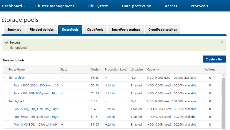
OneFS SSD strategy governs where and how much metadata is placed on SSD or HDD.  There are five SSD Strategies, and these can be configured via OneFS’ file pool policies:

SSD Strategy Description
L3 Cache All drives in a Node Pool are used as a read-only evection cache from L2 Cache.  Currently used data and metadata will fill the entire capacity of the SSD Drives in this mode.  Note:  L3 mode does not guarantee all metadata will be on SSD, so this may not be the most performant mode for metadata intensive workflows.
Metadata Read One metadata mirror is placed on SSD.  All other mirrors will be on HDD for hybrid and archive models.  This mode can boost read performance for metadata intensive workflows.
Metadata Write All metadata mirrors are placed on SSD. This mode can boost both read and write performance when there is significant demand on metadata IO.  Note:  It is important to understand the SSD capacity requirements needed to support Metadata strategies.  Therefore, we are developing the Metadata Reporting Script below which will assist in SSD metadata sizing activities.
Data Place data on SSD.  This is not a widely used strategy, as Hybrid and Archive nodes have limited SSD capacities, and metadata should take priority on SSD for best performance.
Avoid Avoid using SSD for a specific path.  This is not a widely used strategy but could be handy if you had archive workflows that did not require SSD and wanted to dedicate your SSD space for other more important paths/workflows.

Fundamentally, OneFS metadata placement is determined by the following attributes:

  • The model of the nodes in each node pool (F-series, H-series, A-series).
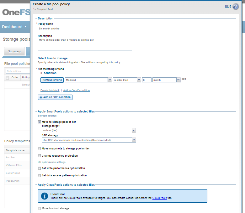
  • The current SSD Strategy on the node pool using configured using the default filepool policy and custom administrator-created filepool policies.
  • The cluster’s global storage pool settings.

The following CLI commands can be used to verify the current SSD strategy and metadata placement details on a cluster. For example, in order to check whether L3 Mode is enabled on a specific node pool:

# isi storagepool nodepool list

ID     Name                       Nodes  Node Type IDs  Protection Policy  Manual

----------------------------------------------------------------------------------

1      h500_30tb_3.2tb-ssd_128gb  1      1              +2d:1n             No

In the output above, there is a single H500 node pool reported with an ID of ‘1’. The details of this pool can be displayed as follows:

# isi storagepool nodepool view 1

                 ID: 1

               Name: h500_30tb_3.2tb-ssd_128gb

              Nodes: 1, 2, 3, 4, 21, 22, 23, 24, 25, 26, 27, 28, 29, 30, 31, 32, 33, 34, 35, 36, 37, 38, 39, 40

      Node Type IDs: 1

  Protection Policy: +2d:1n

             Manual: No

         L3 Enabled: Yes

L3 Migration Status: l3

               Tier: -

              Usage

                Avail Bytes: 321.91T

            Avail SSD Bytes: 0.00

                   Balanced: No

                 Free Bytes: 329.77T

             Free SSD Bytes: 0.00

                Total Bytes: 643.13T

            Total SSD Bytes: 0.00

    Virtual Hot Spare Bytes: 7.86T

Note that if, as in this case, L3 is enabled on a node pool, any changes to this pool’s SSD Strategy configuration via file pool policies, etc, will not be honored. This will remain until L3 cache has been disabled and the SSDs reformatted for use as metadata mirrors.

The following CLI syntax can be used to check the cluster’s default file pool policy configuration:

# isi filepool default-policy view

          Set Requested Protection: default

               Data Access Pattern: concurrency

                  Enable Coalescer: Yes

                    Enable Packing: No

               Data Storage Target: anywhere

                 Data SSD Strategy: metadata

           Snapshot Storage Target: anywhere

             Snapshot SSD Strategy: metadata

                        Cloud Pool: -

         Cloud Compression Enabled: -

          Cloud Encryption Enabled: -

              Cloud Data Retention: -

Cloud Incremental Backup Retention: -

       Cloud Full Backup Retention: -

               Cloud Accessibility: -

                  Cloud Read Ahead: -

            Cloud Cache Expiration: -

         Cloud Writeback Frequency: -

      Cloud Archive Snapshot Files: -

                                ID: -

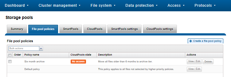
And to list all FilePool Policies configured on a cluster:

# isi filepool policies list

To view a specific FilePool Policy:

# isi filepool policies view <Policy Name>

OneFS also provides global storagepool configuration settings which control additional metadata placement. For example:

# isi storagepool settings view

     Automatically Manage Protection: files_at_default

Automatically Manage Io Optimization: files_at_default

Protect Directories One Level Higher: Yes

       Global Namespace Acceleration: disabled

       Virtual Hot Spare Deny Writes: Yes

        Virtual Hot Spare Hide Spare: Yes

      Virtual Hot Spare Limit Drives: 2

     Virtual Hot Spare Limit Percent: 0

             Global Spillover Target: anywhere

                   Spillover Enabled: Yes

        SSD L3 Cache Default Enabled: Yes

                     SSD Qab Mirrors: one

            SSD System Btree Mirrors: one

            SSD System Delta Mirrors: one

The CLI output below includes descriptions of the relevant metadata options available.

# isi storagepool settings modify -h | egrep -i options -A 30

Options:

    --automatically-manage-protection (all | files_at_default | none)

        Set whether SmartPools manages files' protection settings.

    --automatically-manage-io-optimization (all | files_at_default | none)

        Set whether SmartPools manages files' I/O optimization settings.

    --protect-directories-one-level-higher <boolean>

        Protect directories at one level higher.

    --global-namespace-acceleration-enabled <boolean>

        Global namespace acceleration enabled.

    --virtual-hot-spare-deny-writes <boolean>

        Virtual hot spare: deny new data writes.

    --virtual-hot-spare-hide-spare <boolean>

        Virtual hot spare: reduce amount of available space.

    --virtual-hot-spare-limit-drives <integer>

        Virtual hot spare: number of virtual drives.

    --virtual-hot-spare-limit-percent <integer>

        Virtual hot spare: percent of total storage.

    --spillover-target <str>

        Spillover target.

    --spillover-anywhere

        Set global spillover to anywhere.

    --spillover-enabled <boolean>

        Spill writes into pools within spillover_target as needed.

    --ssd-l3-cache-default-enabled <boolean>

        Default setting for enabling L3 on new Node Pools.

    --ssd-qab-mirrors (one | all)

        Controls number of mirrors of QAB blocks to place on SSDs.

    --ssd-system-btree-mirrors (one | all)

        Controls number of mirrors of system B-tree blocks to place on SSDs.

    --ssd-system-delta-mirrors (one | all)

        Controls number of mirrors of system delta blocks to place on SSDs.

OneFS defaults to protecting directories one level higher than the configured protection policy and retaining one mirror of system b-trees on SSD.  For optimal performance on hybrid platform nodes, the recommendation is to place all metadata mirrors on SSD, assuming the capacity is available.  Be aware, however, that the metadata SSD mirroring options only become active if L3 Mode is disabled.

Additionally, global namespace acceleration (GNA) is a legacy option that allows nodes without SSD to place their metadata on nodes with SSD.  All currently shipping PowerScale node models include at least one SSD drive.


OneFS Neighborhoods

Heterogeneous PowerScale clusters can be built with a wide variety of node styles and capacities, in order to meet the needs of a varied data set and wide spectrum of workloads. Isilon nodes are broken into several classes, or tiers, according to their functionality. These node styles encompass several hardware generations, and fall loosely into four main tiers:

OneFS neighborhoods add another level of resilience into the OneFS failure domain concept.

As we saw in the previous article, disk pools represent the smallest unit within the storage pools hierarchy. OneFS provisioning works on the premise of dividing similar nodes’ drives into sets, or disk pools, with each pool representing a separate failure domain. These are protected by default at +2d:1n (or the ability to withstand two disk or one entire node failure). In Gen6 chassis, disk pools are laid out across all five sleds in each nod.. For example, a node with three drives per sled will have the following disk pool configuration:

Node pools are groups of disk pools, spread across similar, or compatible, OneFS storage nodes. Multiple groups of different node types can work together in a single, heterogeneous cluster.

In OneFS, a failure domain is the portion of a dataset that can be negatively impacted by a specific component failure. A disk pool comprises a group of drives spread across multiple compatible nodes, and a node usually has drives in multiple disk pools which share the same node boundaries. Since each piece of data or metadata is fully contained within a single disk pool, OneFS considers the disk pool as its failure domain.

PowerScale chassis-based hybrid and archive nodes utilize sled protection, where each drive in a sled is automatically located in a different disk pool. This ensures that if a sled is removed, rather than a failure domain losing four drives, the affected failure domains each only lose one drive.

OneFS neighborhoods help organize and limit the width of a disk pool. Neighborhoods also contain all the disk pools within a certain node boundary, aligned with the disk pools’ node boundaries. As such, a node will often have drives in multiple disk pools, but a node will only be in a single neighborhood. Fundamentally, neighborhoods, node pools, and tiers are all layers on top of disk pools, and node pools and tiers are used for organizing neighborhoods and disk pools.

So the primary function of neighborhoods is to improve OneFS reliability in general, and guard against data unavailability. With the PowerScale all-flash F-series nodes, OneFS has an ideal size of 20 nodes per node pool, and a maximum size of 39 nodes. On the addition of the 40th node, the nodes automatically divide, or split, into two neighborhoods of twenty nodes.

Neighborhood F-series Nodes H-series and A-series Nodes
Smallest Size 3 4
Ideal Size 20 10
Maximum Size 39 19

In contrast, the Gen6 chassis based platforms, such as the PowerScale H-series and A-series, have an ideal neighborhood size of 10 nodes per node pool, and an automatic split occurs on the addition of the 20th node, or 5th chassis. This smaller neighborhood size helps the Gen6 hardware protect against simultaneous node-pair journal failures and full chassis failures. With the Gen6 platform and partner node protection, where possible, nodes will be placed in different neighborhoods – and hence different failure domains. Partner node protection is possible once the cluster reaches five full chassis (20 nodes) when, after the first neighborhood split, OneFS places partner nodes in different neighborhoods:

Partner node protection increases reliability because if both nodes go down, they are in different failure domains, so their failure domains only suffer the loss of a single node.

With chassis-level protection, when possible, each of the four nodes within a chassis will be placed in a separate neighborhood. Chassis protection becomes possible at 40 nodes, as the neighborhood split at 40 nodes enables every node in a chassis to be placed in a different neighborhood. As such, when a 38 node Gen6 cluster is expanded to 40 nodes, the two existing neighborhoods will be split into four 10-node neighborhoods:

Chassis-level protection ensures that if an entire chassis failed, each failure domain would only lose one node.

The distribution of nodes and drives in pools is governed by gconfig values, such as the ‘pool_ideal_size’ parameter which indicates the preferred number of nodes in a pool. For example:

# isi_gconfig smartpools | grep -i ideal

smartpools.diskpools.pool_ideal_size (int) = 20

The most common causes of a neighborhood split are:

  1. Nodes were added to the node pool and the neighborhood must be split to accommodate them, for example the nodepool went from 39 to 40 (20+20) or from 59 to 60 (20+20+20).
  2. Nodes were removed from a nodepool into a manual nodepool.
  3. Compatibility settings were changed, which made some existing nodes incompatible.

After a split, typically the Smartpools/SetProtectPlus and AutoBalance jobs run, restriping files so that the new disk pools are balanced.

The following CLI command can be used to identify the correlation between the cluster’s nodes and OneFS neighborhoods, or failure domains:

# sysctl efs.lin.lock.initiator.coordinator_weights

The command output reports the node composition of each neighborhood (failure_domain), as well as the active nodes (up_nodes) in each, and their relative weighting (weights).

With larger clusters, neighborhoods also help facilitate OneFS’ parallel cluster upgrade option. Parallel upgrade provides upgrade efficiency within node pools on larger clusters, allowing the simultaneous upgrading of a node per neighborhood until the pool is complete . By doing this, the upgrade duration is dramatically reduced, while ensuring that end-users still continue to have full access to their data.

During a parallel upgrade, the upgrade framework selects one node from each neighborhood, to run the upgrade job on simultaneously. So in this case, node 13 from neighborhood 1, node 2 from neighborhood 2, node 27 from neighborhood 3 and node 40 from neighborhood 4 will be upgraded at the same time. Considering they are all in different neighborhoods or failure domains, it will not impact the current running workload.  After the first pass completes, the upgrade framework will select another node from each neighborhood and upgrade them, and so on until the cluster is fully upgraded.

For example, consider a hundred node PowerScale H700 cluster. With an ideal layout, there would be 10 neighborhoods, each containing ten nodes. The equation for estimating upgrade a parallel completion time is as follows:

𝐸𝑠𝑡𝑖𝑚𝑎𝑡𝑖𝑜𝑛 𝑡𝑖𝑚𝑒 = (𝑝𝑒𝑟 𝑛𝑜𝑑𝑒 𝑢𝑝𝑔𝑟𝑎𝑑𝑒 𝑑𝑢𝑟𝑎𝑡𝑖𝑜𝑛) × (max 𝑛𝑢𝑚𝑏𝑒𝑟 𝑜𝑓 𝑛𝑜𝑑𝑒𝑠 𝑝𝑒𝑟 𝑛𝑒𝑖𝑔ℎ𝑏𝑜𝑟ℎ𝑜𝑜𝑑)

Assuming an upgrade time of 20 minutes per node, this would be:

20 × 10 = 200 𝑚𝑖𝑛𝑢𝑡𝑒𝑠

So the estimated duration of the hundred node parallel upgrade is 200 minutes, or just under 3 ½ hours. This is in contrast to a rolling upgrade, which would be an order of magnitude greater at 2000 minutes, or almost a day and a half.

OneFS Tiers and Pools

The term ‘tiering’ has been broadly used in data management jargon since the early days of hierarchical storage management (HSM) and information lifecycle management (ILM). Typically, a tier represents a different class of storage hardware. You could have a certain storage array with faster fiber channel drives for active data, and a slower array with large capacity SATA drives for older, infrequently accessed data. The same philosophy holds true with OneFS. However, since SmartPools terminology can prove a touch perplexing at times, this seemed like it would make for a useful blog topic.

The different hardware types within OneFS live within the same cluster as distinct groups of nodes – or ‘node pools’. As for ‘tiers’, this is actually an optional concept in OneFS. Tiers can be built from two or more node pools and accommodate similar but ‘non-compatible’ nodes to coexist in the same container.

Within OneFS, Storage Pools (and the isi storage pools command set) provide a series of abstracted layers for defining these subsets of hardware within a single cluster. This allows data to be optimally aligned with specific sets of nodes by creating data movement rules, or file pool policies. The hierarchy is as such:

Disk pools are the smallest unit within the Storage Pools hierarchy, with each pool representing a separate failure domain. Each drive may only belong to one disk pool and data protection stripes or mirrors don’t extend across pools. Disk pools are managed by OneFS and are not user configurable.

Above this, node pools are groups of disk pools, spread across similar PowerScale storage nodes (compatibility classes). Multiple groups of different node types can work together in a single, heterogeneous cluster.

Each node pool only contains disk pools from the same type of storage nodes and a disk pool may belong to exactly one node pool. Today, a minimum of 3 nodes are required per node pool.

Once node pools have been created, they can be easily modified to adapt to changing requirements. Individual nodes can be reassigned from one node pool to another.  Node pool associations can also be discarded, releasing member nodes so they can be added to new or existing pools. Node pools can also be renamed at any time without changing any other settings in the Node Pool configuration.

Any new node added to a cluster is automatically allocated to a node pool and then subdivided into Disk Pools without any additional configuration steps, inheriting the SmartPools configuration properties of that Node Pool. This means the configuration of disk pool data protection, layout and cache settings only needs to be completed once per node pool and can be done at the time the node pool is first created.

Automatic allocation is determined by the shared attributes of the new nodes with the closest matching node pool.  If the new node is not a close match to the nodes of any existing node pool, it will remain un-provisioned until the minimum node pool compatibility is met.

# isi storagepool health

SmartPools Health

Name                  Health  Type Prot   Members          Down          Smartfailed

--------------------- ------- ---- ------ ---------------- ------------- -------------

h400_30tb_1.6tb-      OK   

ssd_64gb

 h400_30tb_1.6tb-     OK    HDD  +2d:1n 37-38,40-41,43-5 Nodes:        Nodes:

ssd_64gb:47                               5:bay5,8,11,14,1 Drives:       Drives:

                                          7, 39,42:bay8,11

                                          ,14,17

a2000_200tb_800gb-    OK   

ssd_16gb

 a2000_200tb_800gb-   OK    HDD  +2d:1n 57-73:bay5,9,13, Nodes:        Nodes:

ssd_16gb:69                               17,21,           Drives:       Drives:

                                          56:bay5,13,17,21


OK = Ok, U = Too few nodes, M = Missing drives,

D = Some nodes or drives are down, S = Some nodes or drives are smartfailed,

R = Some nodes or drives need repair

When a new node pool is created and nodes are added, SmartPools associates those nodes with an ID. That ID is also used in file pool policies and file attributes to dictate file placement within a specific disk pool.

By default, a file which is not covered by a specific File Pool policy will go to the default node pool(s) identified during set up.  If no default is specified, SmartPools will write that data to the pool with the most available capacity.

Tiers are groups of node pools combined into a logical superset to optimize data storage, according to OneFS platform type:

For example, H Series node pools are often combined into a single tier, as above, in this case including H600, H500, and H400 hardware. Similarly, the archive tier combines A200 and A2000 node pools into a single, logical bucket.

This is a significant benefit because it allows customers who consistently purchase the highest capacity nodes available to consolidate a variety of node styles within a single group, or tier, and manage them as one logical group.

SmartPools users typically deploy between two and four tiers, and the maximum recommended number of tiers is five per cluster. The fastest tier usually comprises all-flash F-series nodes for the most performance demanding portions of a workflow, and the lowest, capacity-optimized tier comprising A-series chassis with large SATA drives.

The following CLI command creates the ‘archive’ tier above and adds two node pools, A200 and A2000, to this tier:

# isi storagepool tiers create archive --children a2000_200tb_800gb-ssd_16gb --children a200_30tb_800gb-ssd_16gb

Additional node pools can be easily and transparently added to a tier. For example, to add the H400 pool above to the ‘archive’ tier:

# isi storagepool nodepools modify h400_30tb_1.6tb- ssd_16gb --tier archive

Or from the WebUI:

Once the appropriate node pools and tiers have been defined and configured, file pool policies can be crafted to govern where data is placed, protected, accessed, and how it moves among the node pools and Tiers. SmartPools file pool policies can be used to broadly control the four principal attributes of a file:

Attribute Description Options
Location Where a file resides ·         Tier

·         Node Pool

I/O The file performance profile (I/O optimization setting) ·         Sequential

·         Concurrent

·         Random

·         SmartCache write caching

Protection The protection level of a file ·         Parity protection (+1n to +4n, +2d:1n, etc)

·         Mirroring (2x – 8x)

SSD Strategy The SSD strategy for a file ·         Metadata-read

·         Metadata-write

·         Data & metadata

·         Avoid SSD

A file pool policy is configured based upon a file attribute the policy can match.  These attributes include File Name, Path, File Type, File Size, Modified Time, Create Time, Metadata Change Time, Access Time or User Attributes.

Once the desired attribute is selected in a file pool policy, action can be taken on the matching subset of files. For example, if the configured attribute is File Size, additional logic is available to dictate thresholds (all files bigger than… smaller than…). Next, actions are applied: move to node pool x, set to y protection level and lay out for z access setting.

Consider a common file pools use case: An organization wants its active data to reside on their hybrid nodes in Tier 1 (SAS + SSD), and to move any data not accessed for 6 months to the cost optimized (SATA) archive Tier 2.

This can be easily achieved via a single SmartPools file pool policy, which can be configured to act either against a tier or nodepool. For example, from the WebUI by navigating to File System > Storage Pools > File Pool Policies:

Or from the CLI using the following syntax:

# isi filepool policies create "Six month archive" --description "Move all files older than 6 months to archive tier" --data-storage-target Archive1 --begin-filter --file-type=file --and --changed-time=6M --operator=gt --end-filter

The newly created file pool policy is applied when the next scheduled SmartPools job runs.

By default, the SmartPools job is scheduled to run once a day. However, the job can also be kicked off manually. For example, via the CLI:

# isi job jobs start SmartPools

Started job [55]

The running SmartPools job can be listed and queried as follows:

# isi job jobs list

ID   Type       State   Impact  Policy  Pri  Phase  Running Time

-----------------------------------------------------------------

55   SmartPools Running Low     LOW     6    1/2    -

-----------------------------------------------------------------

Total: 1
# isi job jobs view 55

               ID: 55

             Type: SmartPools

            State: Running

           Impact: Low

           Policy: LOW

              Pri: 6

            Phase: 1/2

       Start Time: 2022-03-01T22:15:22

     Running Time: 1m 51s

     Participants: 1, 2, 3

         Progress: Visited 495464 LINs (37 processed), and approx. 93 GB:  467292 files, 28172 directories; 0 errors

                   LIN Estimate based on LIN count of 2312 done on Feb 23 23:02:17 2022

                   LIN Based Estimate: N/A Remaining (>99% Complete)

                   Block Based Estimate: 11m 18s Remaining (14% Complete)


Waiting on job ID: -

      Description:

       Human Desc:


As can be seen above, the Job Engine ‘view’ output provides a LIN count-based progress report on the SmartPools job execution status.