PowerScale H710 and H7100 Platforms

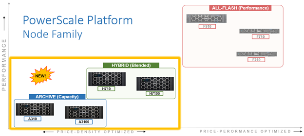
In this article, we’ll take a more in-depth look at the new PowerScale H710 and H7100 hardware platforms that were released last week. Here’s where these new systems sit in the current hardware hierarchy:

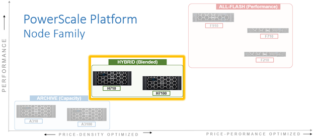
As such, the PowerScale H710 and H7100 are the workhorses of the PowerScale portfolio. Built for general-purpose workloads, the H71x platforms offering flexibility and scalability for a broad range of applications including home directories, file shares, generative AI, editing and post-production media workflows, and medical PACS and genomic data with efficient tiering.

Representing the mid-tier, the H710 and H7100 both utilize a single-socket Zeon processor with 384GB of memory and fifteen (H710) or twenty hard drives per node respectively, plus SSDs for metadata/caching – and with four nodes residing within a 4RU chassis. From an initial 4 node (1 chassis) starting point, H710 and H7100 clusters can be easily and non-disruptively scaled two nodes at a time up to a maximum of 252 nodes (63 chassis) per cluster.

The H71x modular platform is based on Dell’s ‘Infinity’ chassis. Each node’s compute module contains a single 16-core Intel Sapphire Rapids CPU running at 2.0 GHz and with 30MB of cache, plus 384GB of DDR5 DRAM. Front-End networking options include 10/25/40/100 GbE and with both 100Gb Ethernet or Infiniband as selectable options for the Back-End network.

As such, the new H71x core hardware specifications are as follows:

Hardware Class PowerScale H-Series (Hybrid)
Model A310 A3100
OS version Requires OneFS 9.11 or above, and NFP 13.1 or greater.

BIOS based on Dell’s PowerBIOS

Requires OneFS 9.11 or above, and NFP 13.1 or greater.

BIOS based on Dell’s PowerBIOS

Platform Four nodes per 4RU chassis; upgradeable per pair; node-compatible with prior gens. Four nodes per 4RU chassis; upgradeable per pair; node-compatible with prior gens.
CPU 16 Cores @ 2.0GHz, 30MB Cache 16 Cores @ 2.0GHz, 30MB Cache
Memory 384GB DDR5 DRAM 384GB DDR5 DRAM
Journal M.2: 480GB NVMe with 3-cell battery backup (BBU) M.2: 480GB NVMe with 3-cell battery backup (BBU)
Depth Standard 36.7 inch chassis Deep 42.2 inch chassis
Cluster size Max of 63 chassis (252 nodes) per cluster. Max of 63 chassis (252 nodes) per cluster.
Storage Drives 60 per chassis     (15 per node) 80 per chassis     (20 per node)
HDD capacities 2TB,4TB, 8TB, 12TBTB, 16TB, 20TB, 24TB 12TBTB, 16TB, 20TB, 24TB
SSD (cache) capacities 0.8TB, 1.6TB, 3.2TB, 7.68TB 0.8TB, 1.6TB, 3.2TB, 7.68TB
Max raw capacity 1.4PB per chassis 1.9PB per chassis
Front-end network 10/25/40/100 GigE 10/25/40/100 GigE
Back-end network 100 GigE, Infiniband 100 Gb/s Ethernet or Infiniband

These node hardware attributes, plus a variety of additional info and environmentals, can be easily viewed from the OneFS CLI via the ‘isi_hw_status’ command. For example, from an F710:

# isi_hw_status
  SerNo: CF25J243000005
 Config: 1WVXW
ChsSerN:
ChsSlot: 2
FamCode: H
ChsCode: 4U
GenCode: 10
PrfCode: 7
   Tier: 3
  Class: storage
 Series: n/a
Product: H710-4U-Single-192GB-1x1GE-2x100GE QSFP28-240TB-3277GB SSD-SED
  HWGen: PSI
Chassis: INFINITY (Infinity Chassis)
    CPU: GenuineIntel (2.00GHz, stepping 0x000806f8)
   PROC: Single-proc, 16-HT-core
    RAM: 206152138752 Bytes
   Mobo: INFINITYPIFANO (Custom EMC Motherboard)
  NVRam: INFINITY (Infinity Memory Journal) (8192MB card) (size 8589934592B)
 DskCtl: LSI3808 (LSI 3808 SAS Controller) (8 ports)
 DskExp: LSISAS35X36I (LSI SAS35x36 SAS Expander - Infinity)
PwrSupl: Slot1-PS0 (type=ARTESYN, fw=02.30)
PwrSupl: Slot2-PS1 (type=ARTESYN, fw=02.30)
  NetIF: bge0,lagg0,mce0,mce1,mce2,mce3
 BEType: 100GigE
 FEType: 100GigE
 LCDver: IsiVFD2 (Isilon VFD V2)
 Midpln: NONE (No Midplane Support)
Power Supplies OK
Power Supply Slot1-PS0 good
Power Supply Slot2-PS1 good
CPU Operation (raw 0x882D0800)  = Normal
CPU Speed Limit                 = 100.00%
Fan0_Speed                      = 12000.000
Fan1_Speed                      = 11880.000
Slot1-PS0_In_Voltage            = 208.000
Slot2-PS1_In_Voltage            = 207.000
SP_CMD_Vin                      = 12.100
CMOS_Voltage                    = 3.080
Slot1-PS0_Input_Power           = 280.000
Slot2-PS1_Input_Power           = 270.000
Pwr_Consumption                 = 560.000
SLIC0_Temp                      = na
SLIC1_Temp                      = na
DIMM_Bank0                      = 40.000
DIMM_Bank1                      = 41.000
CPU0_Temp                       = -43.000
SP_Temp0                        = 37.000
MP_Temp0                        = na
MP_Temp1                        = 29.000
Embed_IO_Temp0                  = 48.000
Hottest_SAS_Drv                 = -26.000
Ambient_Temp                    = 29.000
Slot1-PS0_Temp0                 = 58.000
Slot1-PS0_Temp1                 = 38.000
Slot2-PS1_Temp0                 = 55.000
Slot2-PS1_Temp1                 = 35.000
Battery0_Temp                   = 36.000
Drive_IO0_Temp                  = 42.000

Note that the H710 and H7100 are only available in a 384GB memory configuration.

Starting at the business end of the chassis, the articulating front panel display allows the user to join the nodes to a cluster, etc:

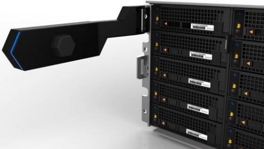
The chassis front panel includes an LCD display with 9 cap-touch back-lit buttons. Four LED Light bar segments, 1 per node, illuminate blue to indicate normal operation or yellow to alert of a node fault. The front panel display is hinge mounted so it can be moved clear of the drive sleds, with a ribbon cable running down the length of the chassis to connect the display to the midplane.

As with all PowerScale nodes, the front panel display provides some useful information for the four nodes, such as the ‘outstanding alerts’ status shown above, etc.

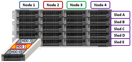
For storage, each of the four nodes within a PowerScale H710/0 chassis’ has five associated drive containers, or sleds. These sleds occupy bays in the front of each chassis, with a node’s drive sleds stacked vertically:

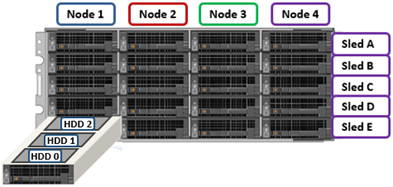
Nodes are numbered 1 through 4, left to right looking at the front of the chassis, while the drive sleds are labeled A through E, with sleds A occupying the top row of the chassis.

The drive sled is the tray which slides into the front of the chassis. Within each sled, the 3.5” SAS hard drives it contains are numbered sequentially starting from drive zero, which is the HDD adjacent the airdam.

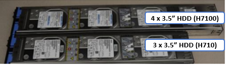
The H7100 uses a longer 42.2 inch, allowing it to accommodate four HDDs per sled compared to three drives for the H710, which is 36.7 inch in depth. This also means that the H710 can reside in a regular 17” data center rack or cabinet, whereas the H7100 requires a deep rack, such as the Dell Titan cabinet.

The H710 and H7100 platforms support a range of HDD capacities, currently including 2TB, 4, 8, 12, 16, 20, and 24TB capacities, and both regular ISE (instant secure erase) or self-encrypting drive (SED) formats.

Each drive sled has a white ‘not safe to remove’ LED on its front top left, as well as a blue power/activity LED, and an amber fault LED.

The compute modules for each node are housed in the rear of the chassis, and contain CPU, memory, networking, and SSDs, as well as power supplies. Nodes 1 & 2 are a node pair, as are nodes 3 & 4. Each node-pair shares a mirrored journal and two power supplies:

Here’s the detail of an individual compute module, which contains a multi core Sapphire Rapids CPU, memory, M2 flash journal, up to two SSDs for L3 cache, six DIMM channels, front-end 40/100 or 10/25 Gb ethernet, back-end 40/100 or 10/25 Gb ethernet or Infiniband, an ethernet management interface, and power supply and cooling fans:

Of particular note is the ‘journal active’ LED, which is displayed as a white ‘hand icon’. When this is illuminated, it indicates that the mirrored journal is actively vaulting.

Note that a node’s compute module should not be removed from the chassis while this while LED is lit!

On the front of each chassis is an LCD front panel control with back-lit buttons and 4 LED Light Bar Segments – 1 per Node. These LEDs typically display blue for normal operation or yellow to indicate a node fault. This LCD display is hinged so it can be swung clear of the drive sleds for non-disruptive HDD replacement, etc.

Details can be queried with OneFS CLI drive utilities such as ‘isi_radish’ and ‘isi_drivenum’. For example, the command output from an H710 node:

tme-1# isi_drivenum

Bay  1   Unit 6      Lnum 15    Active      SN:7E30A02K0F43     /dev/da1
Bay  2   Unit N/A    Lnum N/A   N/A         SN:N/A              N/A
Bay  A0   Unit 1      Lnum 12    Active      SN:ZRS1HP4G         /dev/da4
Bay  A1   Unit 17     Lnum 13    Active      SN:ZR7105GY         /dev/da3
Bay  A2   Unit 16     Lnum 14    Active      SN:ZRS1HNZG         /dev/da2
Bay  B0   Unit 24     Lnum 9     Active      SN:ZRS1PHFG         /dev/da7
Bay  B1   Unit 23     Lnum 10    Active      SN:ZRS1HEA1         /dev/da6
Bay  B2   Unit 22     Lnum 11    Active      SN:ZRS1PHFX         /dev/da5
Bay  C0   Unit 30     Lnum 6     Active      SN:ZR5EFV0D         /dev/da10
Bay  C1   Unit 29     Lnum 7     Active      SN:ZR5FE3Z8         /dev/da9
Bay  C2   Unit 28     Lnum 8     Active      SN:ZR5FE311         /dev/da8
Bay  D0   Unit 36     Lnum 3     Active      SN:ZR5FE3DA         /dev/da13
Bay  D1   Unit 35     Lnum 4     Active      SN:ZRS1PHEF         /dev/da12
Bay  D2   Unit 34     Lnum 5     Active      SN:ZRS1HP6T         /dev/da11
Bay  E0   Unit 42     Lnum 0     Active      SN:ZRS1PHEM         /dev/da16
Bay  E1   Unit 41     Lnum 1     Active      SN:ZRS1PHDV         /dev/da15
Bay  E2   Unit 40     Lnum 2     Active      SN:ZRS1HPAT         /dev/da14

The ‘bay’ locations indicate the drive location in the chassis. ‘Bay 1’ references the cache/metadata SSD, located within the node’s compute module. Whereas the HDDs are referenced by their respective sled (A to E) and drive slot (0 to 2). For example, drive ‘E1’ in the following example:

The H710 and H7100 platforms are available in the following networking configurations, with a 10/25/40/100Gb ethernet front-end and 10/25/40/100Gb ethernet or 100Gb Infiniband back-end:

Model H710 H7100
Front-end network 10/25/40/100 GigE 10/25/40/100 GigE
Back-end network 10/25/40/100 GigE, Infiniband 10/25/40/100 GigE, Infiniband

These NICs and their PCI bus addresses can be determined via the ’pciconf’ CLI command, as follows:

# pciconf -l | grep mlx

mlx4_core0@pci0:59:0:0: class=0x020000 card=0x028815b3 chip=0x100315b3 rev=0x00 hdr=0x00

mlx5_core0@pci0:216:0:0:        class=0x020000 card=0x001615b3 chip=0x101515b3 rev=0x00 hdr=0x00

mlx5_core1@pci0:216:0:1:        class=0x020000 card=0x001615b3 chip=0x101515b3 rev=0x00 hdr=0x00

Similarly, the NIC hardware details and drive firmware versions can be viewed as follows:

# mlxfwmanager
Querying Mellanox devices firmware ...

Device #1:
----------
  Device Type:      ConnectX3
  Part Number:      105-001-013-00_Ax
  Description:      Mellanox 40GbE/56G FDR VPI card
  PSID:             EMC0000000004
  PCI Device Name:  pci0:59:0:0
  Port1 MAC:        1c34dae19e31
  Port2 MAC:        1c34dae19e32
  Versions:         Current        Available
     FW             2.42.5000      N/A
     PXE            3.4.0752       N/A
  Status:           No matching image found

Device #2:
----------
  Device Type:      ConnectX4LX
  Part Number:      020NJD_0MRT0D_Ax
  Description:      Mellanox 25GBE 2P ConnectX-4 Lx Adapter
  PSID:             DEL2420110034
  PCI Device Name:  pci0:216:0:0
  Base MAC:         1c34da4492e8
  Versions:         Current        Available
     FW             14.32.2004     N/A
     PXE            3.6.0502       N/A
     UEFI           14.25.0018     N/A
  Status:           No matching image found

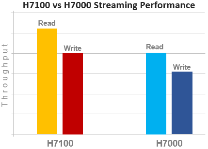
Compared with their H70x predecessors, the H710 and H7100 see a number of hardware performance upgrades. These include a move to DDR5 memory, Sapphire Rapids CPU, and an upgraded power supply.

In terms of performance, the new H71x nodes provide a solid improvement over the prior generation. For example, streaming read and writes on both the H7100 and H7000:

OneFS node compatibility provides the ability to have similar node types and generations within the same node pool. In OneFS 9.11 and later, compatibility between the H710 and H7100 nodes and the previous generation platform is supported. Specifically, this node pool compatibility includes:

PowerScale H-series Node Pool Compatibility Gen6 MLK New
H500 H700 H710
H5600 H7000 H7100
H600

Node pool compatibility checking includes drive capacities for both data HDDs and SSD cache. This pool compatibility permits the addition of H710 node pairs to an existing node pool comprising four or more H700s, if desired, rather than creating an entirely new 4-node H710 node pool. Plus, there’s a similar compatibility between the H7100 and H7000 nodes.

Note that, while the H71x is node pool compatible with the H70x, it does require a performance compromise, since the H71x nodes are effectively throttled to match the performance envelope of the H70x nodes.

Apropos storage efficiency, OneFS inline data reduction support on mixed H-series diskpools is as follows:

Gen6 MLK New Data Reduction Enabled
H500 H700 H710 False
H500 H710 False
H700 H710 True
H5600 H7000 H7100 True
H5600 H7100 True
H7000 H7100 True

In the next article in this series, we’ll turn our attention to the PowerScale A310 and A3100 platforms.

PowerScale H710, H7100, A310, and A3100 Platform Nodes

Hot on the heels of the recent OneFS 9.11 release sees the launch of four new PowerScale hybrid and archive series hardware offerings. Between them, these new H310, H3100, A310 and A3100 spinning-disk-based nodes add significant blended capacity to the PowerScale stable.

Built atop the latest generation of Dell’s PowerScale chassis-based architecture, these new H-series and A-series platforms each boast a range of HDD capacities, paired with SSD for cache, a Sapphire Rapids CPU, a generous helping of DDR5 memory, and ample network connectivity – with four paired nodes all housed within a modular, power-efficient 4RU form factor chassis.

Here’s where these new platforms sit in the current PowerScale hardware hierarchy:

These new platforms will replace the PowerScale H700, H7000, A300, and A3000 systems, and further extend PowerScale’s price-density envelope.

The PowerScale H710, H7100, A310, and A3100 nodes offer an evolution from previous generations, while also focusing on environmental sustainability, reducing power consumption and carbon footprint. Housed in a 4RU chassis with balanced airflow and enhanced cooling, these new platforms offer significantly greater density than their predecessors – plus are ready to support Seagate’s 32TB HAMR HDDs when those drives become available later this year.

These new nodes all require OneFS 9.11 (or later) and also include in-line compression and deduplication by default – further increasing their capacity headroom, effective density, and power efficiency. Plus, incorporating Intel’s 4th gen Xeon Sapphire Rapids CPUs and the latest DDR5 DRAM offers greater processing horsepower plus an improved performance per watt.

Scalability-wise, both platforms require a minimum of four nodes (1 chassis) to form a cluster (or node pool). From here, they can be simply and non-disruptively scaled two nodes at a time up to a maximum of 252 nodes (63 chassis) per cluster. The basic specs for these new platforms are as follows:

Hardware Class PowerScale H-Series (Hybrid) PowerScale A-series (Archive)
Model H710 H7100 A310 A3100
OneFS version Requires OneFS 9.11 or above. Requires OneFS 9.11 or above.
CPU 16 Cores @ 2.0GHz, 30MB Cache 8 Cores @ 1.8GHz, 22.5MB Cache
Memory 384GB DDR5 DRAM 96GB DDR5 DRAM
Platform Four nodes per 4RU chassis; upgradeable per pair; node-compatible with prior generations. Four nodes per 4RU chassis; upgradeable per pair; node-compatible with prior generations.
Depth Standard 36.7 inch chassis Deep 42.2 inch chassis Standard 36.7 inch chassis Deep 42.2 inch chassis
Max cluster size Maximum of 63 chassis (252 nodes) per cluster. Maximum of 63 chassis (252 nodes) per cluster.
Storage Drives 60 per chassis     (15 per node) 80 per chassis     (20 per node) 60 per chassis     (15 per node) 80 per chassis     (20 per node)
HDD capacities 2TB,4TB, 8TB, 12TBTB, 16TB, 20TB, 24TB 2TB,4TB, 8TB, 12TBTB, 16TB, 20TB, 24TB
SSD (cache) capacities 0.8TB, 1.6TB, 3.2TB, 7.68TB 0.8TB, 1.6TB, 3.2TB, 7.68TB
Max raw capacity 1.4PB per chassis 1.9PB per chassis 1.4PB per chassis 1.9PB per chassis
Front-end network 10/25/40/100 GigE 10/25 GigE
Back-end network 10/25/40/100 GigE, Infiniband 10/25 GigE, Infiniband

In concert with the generational CPU and DRAM upgrades in the new PowerScale chassis platforms, OneFS 9.11 software advancements also help deliver a nice performance bump for the H71x and A31x hybrid platforms – particularly for sequential reads and writes.

The PowerScale H-series platforms are designed for general-purpose workloads, offering flexibility and scalability for a wide range of applications including file shares and home directories, editing and post-production media workflows, generative AI, and PACS and genomic data with efficient tiering.

In contrast, the A-series platforms are designed for cooler, infrequently accessed data use cases. These include active archive workflows for the A310, such as regulatory compliance data, medical imaging archives, financial records, and legal documents. And deep archive/cold storage for the A3100 platform, including surveillance video archives, backup, and DR repositories.

Over the next couple of articles, we’ll dig into the technical details of each of the new platforms. But, in summary, when combined with OneFS 9.11, the new PowerScale hybrid H71x and A31x platforms quite simply deliver on efficiency, flexibility, performance, scalability, and affordability!

OneFS SyncIQ Temporary Directory Hashing

SyncIQ receives an update in OneFS 9.11 with the default enablement of its Temporary Directory Hashing feature, which can help improve replication directory delete performance on target clusters.

But first, some background. For several years now, OneFS has included functionality, commonly referred to as temporary directory hashing, which addresses some of the challenges that SyncIQ can potentially encounter with large incremental replication tasks. Specifically, if a cluster contains an extra-wide directory, with many different replication threads trying to write to it simultaneously, OneFS file system performance can be impacted due to contention over lock requests on that very wide directory.

When Sync IQ performs an incremental transfer it frequently uses a temporary working directory in cases such as where a file has been created, but its parent doesn’t exist yet due to LIN order processing – or files being removed and their parents not being available, etc. Instead, SyncIQ will use this temporary working directory as a place to stash these files until it can put them in the correct location. In some incremental replication workflows, this could result in an extra-wide temporary working directory, potentially containing millions or billions of directories entries. When there are hundreds of SyncIQ workers all trying to link and unlink files from that same directory, performance can start to become impacted.

To address this, temporary directory hashing introduces support for subdirectories within a large temp working directory, based on a directory cookie. This allows SyncIQ to split up that monolithic directory into a bunch of smaller ones, so workers don’t contend with all of the other workers when they’re trying to link and unlink files within their temporary directories. They only contend with the other workers in their particular subdirectory, often providing a significant performance boost in some cases with lots of concurrent access.

In OneFS 9.11, temporary directory hashing functionality now becomes the default configuration and behavior.

SyncIQ’s temporary directory hashing functionality has actually existed within OneFS since 8.2, but prior to OneFS 9.11 it had to be manually enabled on a per-policy basis for any desired replication workflows.

When installing or upgrading a cluster to OneFS 9.11 or later, temporary directory hashing becomes the default configuration, so that any new SyncIQ policies will automatically have temporary directory hashing will enabled. However, this default change will not be applied retroactively to any legacy policies that were configured prior to OneFS 9.11 upgrade.

That said, any pre-existing policies can be easily configured to use temporary directory hashing from the SyncIQ source cluster with the following CLI syntax:

# echo '{"enable_hash_tmpdir": true}' | isi_papi_tool PUT /7/sync/policies/<policy name>

For example:

# echo '{"enable_hash_tmpdir": true}' | isi_papi_tool PUT /7/sync/policies/remote_zone1

Type request body, press enter, and CTRL-D:

204

Content-type: text/plain

Allow: GET, PUT, DELETE, HEAD

The configuration can be verified as ‘enabled’ with the following command:

# isi_papi_tool GET /7/sync/policies/remote_zone1 | grep "enable_hash_tmpdir"

"enable_hash_tmpdir" : true,

Under the hood, temporary directory hashing places any directories within a SyncIQ policy which need to be deleted into subdirectories under the ./tmp-working-dir/ directory, instead at the root of tmp-working-dir. This lowers contention on the root tmp-working-dir by moving exclusive locking requests to those subdirectories.

Performance-wise, the benefit and efficiency of SyncIQ temporary directory hashing will vary by cluster constitution, environment, and workflow. However, environments with thousands of directory deletions per policy run have seen improvements of between 2x-20x faster delete performance. To determine whether this feature is proving beneficial for a specific policy, view the SyncIQ job reports and compare the ‘STF_PHASE_CT_DIR_DELS’ job phase start and end times. This will indicate how much time those jobs have spent in this temporary directory delete phase, and can be accomplished from the replication source cluster with the following CLI syntax:

# isi sync reports view <policy_name> <job_id> | grep -C 3 "CT_DIR_DELS"

For example:

# isi sync reports view remote_zone1 31 | grep -C 3 "CT_DIR_DELS"

                            Phase: STF_PHASE_CT_DIR_DELS

                       Start Time: 2025-06-06T16:12:39

                         End Time: 2025-06-06T16:10:47

Note that for some SyncIQ policies which routinely move wide and shallow directories from one directory to another, temporary directory hashing may actually adversely impact those moves. In such instances, the feature can be disabled for each individual SyncIQ replication policy as follows:

# echo '{"enable_hash_tmpdir": false}' | isi_papi_tool PUT /7/sync/policies/<policy name>

Note that the above command should be run on the replication source cluster, using the root user authenticating to the PAPI service, replacing <policy name> with the appropriate value.

For example:

# echo '{"enable_hash_tmpdir": false}' | isi_papi_tool PUT /7/sync/policies/remote_zone1

Type request body, press enter, and CTRL-D:

204

Content-type: text/plain

Allow: GET, PUT, DELETE, HEAD

As such, OneFS will have disabled this feature for all subsequent job runs.

Similarly, the configuration can be verified as follows:

# isi_papi_tool GET /7/sync/policies/remote_zone1 | grep "enable_hash_tmpdir"

"enable_hash_tmpdir" : false,

For clusters running OneFS 8.2 through OneFS 9.10, where SyncIQ temporary directory deletion is disabled by default, it can be activated on a per-policy basis as follows:
# echo '{"enable_hash_tmpdir": true}' | isi_papi_tool PUT /7/sync/policies/<policy name>

As such, the next time SyncIQ runs the specified policy, temporary directory hashing will be enabled for this and future job runs.

So, in summary, SyncIQ temporary directory hashing can improve SyncIQ directory deletion performance for many policies with wide directory cases. While in OneFS 9.10 and earlier it was manually configurable on an individual per policy basis, now, in OneFS 9.11 and later, temporary directory hashing is enabled by default on all new Sync IQ policies.

OneFS S3 Conditional Writes and Cluster Status Reporting API

In addition to the core file protocols, PowerScale cluster also supports the ubiquitous AWS S3 protocol. As such, applications have multiple access options to the same underlying dataset, semantics, across both file and object.

Also, since OneFS objects and buckets are essentially files and directories within the /ifs filesystem, the same OneFS data services, such as Snapshots, SyncIQ, WORM, etc, are all seamlessly integrated. This makes it possible to run hybrid and cloud-native workloads, which use S3-compatible backend storage – for example cloud backup & archive software, modern apps, analytics flows, IoT workloads, etc. – and to run these on-prem, alongside and coexisting with traditional file-based workflows.

The recent OneFS 9.11 release further enhances the PowerScale S3 protocol implementation with two new features: The addition of conditional write support and API-based cluster status reporting.

First, the new S3 conditional write support prevents the overwriting of existing S3 objects with identical key names. It does this via pre-condition arguments to the S3 ‘PutObject’ and ‘CompleteMultipartUpload’ requests with the addition of an ‘If-None-Match’ HTTP header. As such, if the condition is not met, the S3 operation(s) fail. Note, however, that OneFS does not currently support the ‘If-Match’ HTTP header, which checks the Etag value. More information about S3 conditional write is provided in the following AWS documentation: https://docs.aws.amazon.com/AmazonS3/latest/userguide/conditional-requests.html

The second new piece of S3 functionality in OneFS 9.11 is API-based cluster status reporting. Increasingly, next gen applications need a reliable method decide where to store their backups and large data blobs across a variety of storage technologies. As such, a consistent API format, including cluster health status reporting, is needed to answer general questions about any S3 endpoint that maybe be under consideration as a potential target – particularly for applications without access to the management network. So providing the cluster status API facilitates intelligent decision making, such as how best to balance load and capacity across multiple PowerScale clusters. Additionally, the cluster status data can also help with performance analysis, as well as diagnosing hardware issues. For example, if an endpoint-alert has had zero successful objects delivered to it in the last hour, this status object will be the first thing that gets queried to see if there is a visible issue, or if applications are ‘routing around’ by intentionally using other resources.

The API uses an S3 endpoint with the following URL format:

S3://cluster-status/s3_cluster_status_v1

This mimics the GET object operation in the S3 service and is predicated on a via virtual bucket and object. As such, HEAD requests on this virtual bucket and object are valid, as is a GET request on the virtual object to read the Cluster Status data. All other S3 calls to this virtual bucket and object are prohibited, and the 405 HTTP error code returned.

Applications and users can use the S3 SDK, or other S3-conversant utility such as ‘s5cmd’, to retrieve the cluster status object, which involves the three valid S3 requests mentioned above:

  • HEAD bucket
  • HEAD object
  • GET object

Where the ‘get object’ request returns the cluster status details. For example, using the ‘s5cmd’ utility from a windows client:

C:\s5cmd_2.3.0> .\s5cmd.exe –endpoint-url=http:10.10.20.30:9020 cat s3://cluster-status/s3_cluster_status_v1

{

   “15min_avg_read_bw_mbs” : “0.12”,

   “15min_avg_write_bw_mbs” : “0.04”,

   “capacity_status_age_date” : “2025/06/04T07:43:02”,

   “health” : “all_nodes_operational”,

   “health_percentage” : “100”,

   “health_status_age_date” : “2025/06/04T07:43:02”,

   “mgmt_name” : “10.10.20.30:8080”

   “net_state” : “full”,

   “net_state_age_date” : “2025/06/04T07:43:02”,

   “net_state_calculation” : {

      “available_percentage” : “99”,

      “down_bw_mbs” : “0”,

      “total_bw_mbs” : “3576”,

      “used_bw_mbs” : "0.01”,

   },

   “total_capacity_tb” : :0.06”,

   “total_capacity_tib” : :0.05”,

   “total_free_space_tb” : :0.06”,

   “total_free_space_tib” : :0.05”,

}

The response format is JSON, and authenticated S3 users can access these APIs and download the cluster status object. The table below includes details of each response field:

Requested Field Description
mgmt_name Management interface name of this cluster.
total_capacity_tb Cluster’s total “current” capacity in base 10 terabytes.
total_capacity_tib Cluster’s total “current” capacity in base 2 terabytes(tebibytes).
total_free_space_tb Cluster’s total “current” free space in base 10 terabytes.
total_free_space_tib Cluster’s total “current” free space in base 2 terabytes(tebibytes).
capacity_status_age_date Number of second between the time of issuance and the proper calculation of capacity status.
health Calculated status based on per node health status:  either all_nodes_operational or some_nodes_nonoperational or non_operational.
health_percentage Vendor specific number from 0-100% where the vendor’s judgement should be used has to what level of the systems normal load it can take.
health_status_age_date Number of second between the time of issuance and the proper calculation of health status.
15min_avg_read_bw_mbs Read bandwidth in use, measured in megabytes per second, averaged over a 15-minute period.
15min_avg_write_bw_mbs Write bandwidth in use, measured in megabytes per second, averaged over a 15-minute period.
net_state Networking status to S3 clusters. Divided into “Full”, “Half”, “Critical”, and “Unknown”
net_state_age_date Number of second between the time of issuance and the proper calculation of network status.

These fields can be grouped into the following core categories:

Category Description
Capacity Reports the total capacity and available capacity in both terabytes and tebibytes.
Health Includes the cluster health, node health and network health.
Management ‘Management name’ references the out-of-band management interface that admins can use to configure the cluster.
Networking Network status takes both the interfaces up/down status and the read write bandwidth on each interface into consideration.
Performance Includes the read and write bandwidth.

Under the hood, The high-level cluster reporting API operational workflow can be categorized as follows:

When an S3 client sends a get cluster status request, the OneFS S3 service retrieves the data from isi_status_d and Flexnet services. As part of this transaction, the calculations are performed and the result returned to the S3 client in JSON format. To speed up the retrieve process, a memory cache retains the data with a configured expiry time.

Configuration-wise, the addition of the cluster status API in OneFS 9.11 introduces the following new gconfig parameters:

Name Default Value Description
S3ClusterStatusBucketName “cluster-status” Name of the bucket used to access cluster status.
S3ClusterStatusCacheExpirationInSec 300 Expiration time in seconds for cluster status cache in memory. Once reached, the next request for cluster status will results in a new fetch of fresh data.
S3ClusterStatusEnabled 0 Boolean parameter controlling whether the feature is enabled or not.

0 = disabled; 1 = enabled

S3ClusterStatusObjectName “s3_cluster_status_v1” Name of the object used to access cluster status.

These parameter values can be viewed or configured using the ‘isi_gconfig’ CLI utility. For example:

# isi_gconfig | grep S3Cluster

registry.Services.lwio.Parameters.Drivers.s3.S3ClusterStatusBucketName (char*) = cluster-status

registry.Services.lwio.Parameters.Drivers.s3.S3ClusterStatusCacheExpirationInSec (uint32) = 300

registry.Services.lwio.Parameters.Drivers.s3.S3ClusterStatusEnabled (uint32) = 0

registry.Services.lwio.Parameters.Drivers.s3.S3ClusterStatusObjectName (char*) = s3_cluster_status_v1

The following gconfig CLI command syntax can be used to activate this feature, which is disabled by default:

# isi_gconfig registry.Services.lwio.Parameters.Drivers.s3.S3ClusterStatusEnabled=1

# isi_gconfig | grep S3Cluster | grep -i enabled

registry.Services.lwio.Parameters.Drivers.s3.S3ClusterStatusEnabled (uint32) = 1

Two new operations are added to the S3 service, namely ‘head S3 cluster status’ and ‘get S3 cluster status’. For the head bucket, it will always return 200. For head cluster status object, the following three fields are required:

  • ‘content-length’, which is the length of the cluster status object
  • ‘last modified date’ maps the date for getting the cluster status object
  • an empty ‘etag’

Note that OneFS uses the MD5 hash of an empty string for the empty value.

The S3 cluster status API is available once OneFS 9.11 has been successfully installed and committed. and S3 service is enabled. During upgrade to 9.11 the ‘404 Not Found’ will be returned if the API endpoints are queried.

There are a couple of common cluster status API issues to be aware of. These include:

Issue Troubleshooting step(s)
The get cluster status API fails to get the cluster status and returns 404 Check if the configuration: S3ClusterStatusEnabled has been set to 1, or if the S3ClusterStatusBucketName and S3ClusterStatusObjectName match the bucket name and object name requested in the API.
The get cluster status API fails to get the cluster status and returns 403 Check if the access key is input correctly and if the user is an authenticated user
The get cluster status API frequently returns “unknown” value Verify that the dependent services (ie. isi_status_d) is running

Helpful log files for further investigating API issues such as the above include the S3 protocol log, Stats daemon log, and Flexnet service log. These can be found at the following locations on each node:

Logfile Location
S3 protocol log /var/log/s3.log
Flexnet daemon log /var/log/isi_flexnet_d.log
Stats daemon log /var/log/isi_stats_d.log

Additionally, the following CLI utilities can also be useful troubleshooting tools:

# isi_gconfig

# isi services s3