PowerScale InsightIQ 6.4

The dog days of summer have done nothing to slow the pace over at Dell PowerScale. Hot on the heels of the OneFS 9.15 release comes the arrival of the latest and greatest PowerScale InsightIQ 6.4 monitoring and reporting release.

As a quick refresher, InsightIQ provides robust health, performance, and reporting capabilities that help maximize PowerScale cluster efficiency, including advanced analytics to optimize applications, correlate cluster events, and accurately forecast future storage requirements.

So what goodness does this InsightIQ 6.4 release add to the PowerScale metrics and monitoring mix?

New functionality includes:

Feature IIQ 6.4 Functionality
Top Talkers Report New report type surfacing the top N clients slowing a cluster down, ranked by bandwidth, latency, and operation rate.
Performance Anomaly Detection On-demand anomaly detection across the Performance Reports modules, highlighting unusual behavior directly on the existing performance graphs.
Dell ESE Integration Secure, always-on connectivity to Dell support infrastructure via Connectivity Services, enabling remote troubleshooting without VPN or direct network access.
Telemetry Automated, periodic collection of system health, configuration, and feature-adoption metadata, uploaded securely over the same ESE channel. No customer PII or cluster data.
Partitioned Performance Enhancements New SmartQoS identification and workload-latency metrics, plus support for 1,024+ workloads per dataset.
AI Assistant Enhancements Bring Your Own LLM (BYO-LLM) support, multi-session chat history, and response-feedback collection.
Platform & OS Support Support for the latest OS and OneFS releases, plus N-2 version upgrade support for simplified upgrade planning.

The new PowerScale InsightIQ 6.4 release introduces a healthy crop of enhancements aimed at improving performance visibility, supportability, and day-to-day usability. Let’s take a closer look at each of them in turn.

Top Talkers Report

Top of the bill in 6.4 is the new Top Talkers report, added to the Performance Reports family. Rather than trawling through graphs to work out which client is hammering a cluster, administrators can now see the busiest clients at a glance. The report presents bar charts of the top N clients across three brand-new modules — Bandwidth, Latency, and Op Rate — making it straightforward to pinpoint the workloads that are slowing a monitored cluster down.

Because Top Talkers lives within Performance Reports, it behaves just like its siblings: the usual filters can be applied (single-value filters are supported for these new modules), and the modules can be freely mixed and matched into custom user-defined reports.

Performance Anomaly Detection

InsightIQ 6.4 also gains on-demand Performance Anomaly Detection — a built-in capability that automatically flags unusual performance patterns on your monitored clusters. Anomalies are highlighted directly on the existing performance reporting graphs, with InsightIQ computing expected upper and lower confidence bounds for each metric and marking any data point that breaches them. It works across all performance report types, with the sole exception of multiline graphs.

Two detection modes are on offer, depending on how much history is available:

Historic Mode Current View Mode
Uses past trends and seasonality (hourly, daily, weekly) to establish a baseline. Detects anomalies using only the data visible on the current graph.
Requires a minimum of one week of historical data. Works for any selected time duration.
Configurable lookback window of 1, 2, or 3 weeks (default: 2 weeks). No historical data requirement.
Best for steady-state workloads with predictable patterns. Useful when historical data is limited or the cluster is newly added.

Three sensitivity levels — Low, Medium, and High — control the strictness of the confidence bounds, with higher sensitivity flagging subtler deviations. Historic mode builds its baseline from up to three weeks of past data, learning the hourly, daily, and weekly seasonality unique to each cluster’s workload. To use Historic mode, at least one PowerScale cluster must be added, actively monitored, in a Connected state, and have a minimum of one week of collected performance data.

Dell ESE Integration (Connectivity Services)

Arguably the headline supportability feature of the release, InsightIQ 6.4 introduces integration with Dell’s backend through ESE Connectivity Services. This establishes secure, always-on connectivity between InsightIQ and Dell Technologies support infrastructure, allowing Dell support engineers to remotely access and troubleshoot an InsightIQ instance without requiring a VPN, direct network access, or customer-side coordination during the session. Once configured, a dedicated support user is automatically provisioned for those remote sessions.

Two core capabilities ride on this new channel:

  • Remote Support — Dell support engineers can initiate secure remote CLI (SSH) or Web UI sessions to the InsightIQ instance, authenticated via a time-limited RSC passcode tied to an active Service Request.
  • Auto Support Case Creation — InsightIQ can automatically open support cases with Dell when qualifying events are detected. This can be enabled in the 6.4 release, though it is not yet internally active.

Connectivity can be established in one of two modes, depending on whether the InsightIQ instance is permitted direct internet access:

Connection Mode Description
Connect Directly InsightIQ connects out over the internet directly to Dell Connectivity Services. Requires outbound internet access from the IIQ instance.
Via Secure Connect Gateway InsightIQ connects over port 9443 to a Secure Connect Gateway (SCG) appliance, which acts as a secure proxy to Dell Connectivity Services — useful when IIQ cannot have direct internet access. IIQ monitors only its connection to the gateway; the gateway-to-Dell link is not checked by IIQ. The SCG appliance must be acquired and set up independently.

From a security standpoint, the auto-provisioned support user is deliberately constrained. Via the Web UI it holds a read-only role — able to view the InsightIQ interface but unable to modify any settings or data. Via CLI (SSH) it is limited to non-disruptive operations such as log collection and diagnostics; session-disrupting operations are blocked, with the sole exception of ‘system-reboot’. All remote sessions auto-terminate after 20 minutes of inactivity, and the support user’s credentials are managed internally by InsightIQ and the Dell backend, rather than by IIQ users. Prerequisites are modest: a machine-id (/etc/machine-id) must be present on Scale setups, and an Access Key and PIN are generated up front via the Dell support portal.

Telemetry

Complementing the ESE integration, InsightIQ 6.4 adds Telemetry — the automated, periodic collection of operational metrics and configuration data from InsightIQ, securely uploaded to the Dell ESE connectivity hub. Telemetry rides on the very same connectivity channel and runs quietly in the background as long as connectivity is enabled; no customer action is required after the initial setup. Data is gathered at staggered intervals, compressed into timestamped .tar.gz archives, and uploaded with MD5 checksum integrity verification. Crucially, no customer PII or cluster data content is collected — only system health, configuration metadata, and operational counters.

The collected data gives Dell health monitoring (IIQ health status, cluster connectivity, and critical alerts), deployment visibility (version, deployment mode, host specs, and cluster configuration across the installed base), and feature-adoption insight (which features such as FSA, Quotas, Dedupe, Performance Reporting, and the AI Assistant are actively in use). The collection cadence is pre-configured as follows:

Frequency Data Collected
Every 15 minutes Overall IIQ health; clusters with data-collection failures; critical alerts in the last 15 minutes.
Every 1 hour Cluster connectivity status; datastore usage %; node count; OneFS version; per-cluster node health (nodes up vs. nodes down).
Every 4 hours Total node count across all monitored clusters; per-cluster feature availability (FSA, Quotas, Dedupe).
Every 24 hours Alerts generated in the last 24h; storage usage (percent used, total capacity, per-cluster DB size); deployment info (version, Simple/Scale mode); host info (OS & kernel, CPU cores, RAM, IIQ storage used); alert configuration; performance-reporting configuration; and AI Assistant feedback.

Partitioned Performance Report Enhancements

Keeping step with the latest PowerScale release, InsightIQ 6.4 extends its Partitioned Performance reporting to embrace the newest SmartQoS capabilities. Three enhancements land here:

  • New identification metrics — The new Identification Metrics for performance datasets — Operation Class and File — are now displayed in the breakout values and can be filtered on as normal.
  • Workload latency metrics — The new latency metrics ReadQoSDelay, WriteQoSDelay, and OtherQoSDelay appear as three new lines in the Workload Latency graph, with breakouts displayed as normal when selected from the Breakout By dropdown — a boon for SmartQoS latency analysis.
  • More workloads per dataset — Support has been added for OneFS’s new configurable workload limit, so InsightIQ now handles 1,024+ workloads per user-defined dataset. Dell recommends bumping the deployment VM to 12 CPUs and 32 GB RAM to comfortably absorb the higher expected load.

AI Assistant Enhancements

The document-aware AI Assistant introduced in InsightIQ 6.3 — the intelligent companion that helps users find information, understand product capabilities, and troubleshoot InsightIQ and PowerScale issues directly within the interface — receives a trio of enhancements in 6.4:

  • Bring Your Own LLM (BYO-LLM) — Enables integration with an external, OpenAI-compatible LLM. User queries can be securely routed to the configured external model for response generation, rather than relying solely on the built-in assistant.
  • Chat history — Supports multiple chat sessions, letting users switch between conversations while maintaining context across interactions.
  • Response feedback — Lets users rate the AI-generated responses. That feedback is gathered through telemetry to help improve the overall experience over time.

Enabling the AI Assistant is a prerequisite for all of the above. For BYO-LLM specifically, an OpenAI-compatible API endpoint, valid API credentials, and — where applicable — the required SSL/TLS certificates are needed.

Ecosystem & Platform Support

On the platform front, InsightIQ 6.4 keeps pace with the latest operating system and OneFS releases. The headline changes since 6.3 are the move to SLES 15 SP6 for Scale deployments and extended PowerScale coverage up to OneFS 9.15. The full qualification matrix is as follows:

Qualified On InsightIQ 6.3 InsightIQ 6.4
OS (Scale deployment) RHEL 8.10, RHEL 9.6, RHEL 10.0, SLES 15 SP4 RHEL 8.10, RHEL 9.6, RHEL 10.0, SLES 15 SP6
PowerScale (OneFS) v9.7 to v9.14 v9.7 to v9.15
VMware ESXi ESXi v8.0 U3, ESXi v9.0.1 ESXi v8.0 U3, ESXi v9.0.1
VMware Workstation Workstation 17 Free Version Workstation 17 Free Version
Ubuntu Ubuntu 24.04 Online deployment Ubuntu 24.04 Online deployment
OpenStack RHOSP v21 with RHEL 10.0 RHOSP v21 with RHEL 10.0

As with prior releases, InsightIQ continues to offer the same two deployment models — the bare-metal / virtual-machine InsightIQ Scale flavour and the OVA-based InsightIQ Simple flavour on a VMware hypervisor — so existing customers can stick with the model that best suits their environment.

Upgrading to InsightIQ 6.4

One of the more welcome operational touches in this release is N-2 upgrade support, which simplifies upgrade planning by allowing a direct, in-place upgrade to 6.4 from either the 6.2.0 or 6.3.0 release — the process is identical on both Simple and Scale deployments. Beyond an existing InsightIQ Simple or Scale machine running 6.2.0 or 6.3.0, the only real prerequisite is at least 40 GB of free disk space.

At a high level, the upgrade is driven by a single script and moves through a precheck, the upgrade itself, and a post-upgrade cleanup:

  • Precheck — Docker availability, an InsightIQ version check (6.2.0 or 6.3.0), free disk space, InsightIQ service status, and OS compatibility.
  • Upgrade — EULA acceptance, extraction of the InsightIQ images, service shutdown, resource-limit updates, add-on and CIAM installation, and the InsightIQ service upgrade itself.
  • Post-upgrade — InsightIQ metadata refresh, re-enabling of the AI Assistant (if opted in), removal of old Docker images, and clean-up of the upgrade and backup folders.

The mechanics themselves are refreshingly simple — download and uncompress the bundle, extract the upgrade scripts, and trigger ./upgrade-iiq.sh. Progress can be tracked at any time with the showupg –log and showupg –status helpers, with the full detail available in the insightiq_upgrade.log under /usr/share/storagemonitoring/logs/.

All told, InsightIQ 6.4 is a hearty release: Top Talkers and Performance Anomaly Detection sharpen the day-to-day performance story, the ESE integration and Telemetry step change the supportability experience, and the SmartQoS, AI Assistant, and platform updates round things out nicely.

OneFS pNFS Configuration and Management

As we saw in the previous article in this series, with OneFS 9.15, any node in a PowerScale cluster can now act as the OneFS metadata server (MDS), or serve data connections (DS). This separation of the metadata path from the data path allows file I/O traffic to be distributed across multiple nodes in the cluster, thereby maximizing available bandwidth and parallelism.

In this article, we turn our attention to the enablement, configuration, and management of pNFS.

When a pNFS‑capable client mounts an NFS export on a pNFS‑enabled OneFS cluster, each node functions as both a Metadata Server and a Data Server, with the Metadata Server role being implicitly assigned to the node the client initially contacts during the mount.

Data I/O operations are performed using NFSv3, as permitted by the pNFS Flexible File Layout specification, while NFSv4.1 or NFSv4.2 is used exclusively for layout management and metadata operations. Layouts are granted on a per‑file basis, with the client requesting a layout upon file open that specifies the appropriate data server or servers for that file. Different files may be assigned to different nodes, and traffic distribution behavior is influenced by server‑side alignment settings. The set of data server addresses provided to the client is determined by the SmartConnect pool associated with the mount IP address.

In order for pNFS to activated, a cluster must be running OneFS 9.15, with NFSv4.1 or NFSv4.2 enabled for metadata operations and NFSv3 enabled for data operations. The SmartConnect pool must also use static IP allocation.

Attribute Details
OneFS version OneFS 9.15 to provide pNFS support.
NFS protocol versions NFSv4.1 or NFSv4.2 must be enabled (for the metadata path). NFSv3 must also be enabled (for the data path).
SmartConnect pool type The SmartConnect network pool hosting pNFS must use Static IP allocation.
Client OS Linux with kernel pNFS Flexible File Layout support (available in mainline Linux kernels 5.14+).
Client mount options The client must mount the cluster export using NFSv4.1 (-o vers=4.1) or NFSv4.2 (-o vers=4.2). Transport protocol may be RDMA (proto=rdma) or TCP (proto=tcp). UDP is unsupported.

On the client side, systems must be running Linux kernels that support the pNFS Flexible File Layout, which is available in mainline kernels version 5.14 and later. Additionally, mounts must explicitly specify NFSv4.1 or NFSv4.2 using either TCP or RDMA transport, as UDP is not supported.

With OneFS 9.15, pNFS configuration can be performed via the OneFS CLI or platform API (pAPI), but the WebUI does not currently have an equivalent. Under the hood, the configuration is managed by the  ‘isi_gconfig’ registry keys under the NFS driver path. Client remounts are strongly recommended when enabling or disabling pNFS, as clients cache file attributes that determine layout eligibility, so may otherwise retain stale information. Activation requires unmounting NFS clients, enabling the pNFS feature from the OneFS CLI, and restarting the NFS service, with a corresponding process to disable the feature.

Several configuration parameters control pNFS behavior, including a master enablement flag for advertising Metadata Server and Data Server capabilities, alignment settings that determine how file data is distributed across nodes, options for mapping network interfaces to pNFS devices, and internal settings governing layout tracking scalability. In particular, the stripe alignment configuration has a substantial impact on I/O distribution patterns and must be carefully considered when tuning performance, as different alignment values favor different workload characteristics.

Facet Details
Layout Layouts are per-file. Each time a client opens a file, it requests a layout that tells it which data server to use. Different files may be assigned to different nodes. How the client spreads its traffic also depends on the server settings around alignment.
Network SmartConnect determines the pool. The set of data server addresses returned to the client comes from the SmartConnect pool that the client’s mount IP belongs to.
Node roles Every node in the cluster acts as both a Metadata Server and a Data Server. The ‘MDS’ role simply means the node the client happened to connect to for that mount.
Protocol version Data I/O uses NFSv3. The pNFS Flexible File Layout standard allows data servers to speak NFSv3, which is well-supported and performant. The client uses NFSv4.1 only for metadata and layout management.

Every node in the cluster functions as both a Metadata Server (MDS) and a Data Server (DS), with the MDS role simply representing the node to which the client initially connects during the mount operation. Data I/O operations are performed using NFSv3, as permitted by the pNFS Flexible File Layout specification, while NFSv4.1 is used exclusively by the client for metadata handling and layout management. Layouts are granted on a per‑file basis, such that each time a file is opened, the client requests a layout identifying the appropriate data server, allowing different files to be serviced by different nodes, with overall traffic distribution further influenced by server‑side alignment configurations. The set of data server addresses provided to the client is determined by SmartConnect, with the addresses drawn from the SmartConnect pool associated with the client’s mount IP.

When it comes to enabling pNFS, ensure that the following prerequisites are met:

OneFS version OneFS 9.15 or later.
NFS protocol versions NFSv4.1 or NFSv4.2 must be enabled for the metadata path. Additionally, NFSv3 must also be enabled for the data path.
SmartConnect pool type The pool must use static IP allocation. Dynamic IP pools are not currently supported for pNFS because device addresses must remain stable.
Client OS Linux with kernel pNFS Flexible File Layout support (available in mainline Linux kernels 5.14+).
Client mount options The client must mount using either NFSv4.1 (-o vers=4.1) or NFSv4.2 (-o vers=4.2). Transport protocol may be RDMA (proto=rdma) or TCP (proto=tcp). UDP is unsupported.

OneFS pNFS support can be enabled via the CLI as follows:

  1. First, verify that the desired SmartConnect network pool is configured for static IPs:
# isi network pools list
  1. Next, check that NFSv3 and NFSv4.1 and/or NFSv4.2 are enabled:
# isi nfs settings global view
  1. When both the above prerequisites are confirmed, activate pNFS as follows:
# isi nfs settings global modify --pnfs-enabled 1
  1. Once done, the cluster’s NFS exports can then be mounted from a Linux client running kernel 5.14+. For example:
# mount -t nfs4 -o vers=4.1 <pool-ip>:/ifs/data /mnt/pnfs
  1. From the NFS client, after performing some I/O, the ‘mountstats’ file contents or CLI command can be used to verify pNFS is active. For example:
# grep -A 20 "pnfs" /proc/self/mountstats

Or:

# mountstats --nfs /mnt/pnfs

Specifically, the presence of non-zero ‘pNFS_read’ and ‘pNFS_write’ counters in the output confirms that the Linux client is using pNFS.

Optionally, as a second part to step 3 above, NIC-level device granularity configuration can also be applied. For example:

# isi_gconfig registry.Services.lwio.Parameters.Drivers.nfs.NFSV4LayoutDeviceUseNICAsUniqueDevice=1

Followed by an NFS service restart:

# isi services nfs disable && isi services nfs enable

Additionally, if pNFS does need to be disabled for any reason, first unmount any NFS clients, then run the following CLI command:

# isi nfs settings global modify --pnfs-enabled=true

The OneFS pNFS implementation (and the pNFS spec in general) does not require any changes to applications, as it is negotiated transparently between the NFS client and server. This allows applications to continue reading and writing files normally while the client kernel automatically manages layout negotiation and communication with data servers.

If a data server node becomes unavailable while a client holds a layout, the client may encounter I/O errors on the NFSv3 data path to that node. However, most Linux NFS clients will fall back to performing I/O through the metadata server (MDS) until the data server becomes available again, at which point they can re-request a layout, with the exact behavior varying by client kernel version and implementation.

OneFS pNFS is supported with both NFSv4.1 and NFSv4.2 and can coexist with non-pNFS clients on the same export, since pNFS is negotiated individually during session setup and clients that do not support it will continue using traditional NFS I/O paths while still accessing the same files.

Additionally, pNFS can work with RDMA when the server advertises both TCP and RDMA data server addresses and the environment includes RDMA-capable interfaces, enabling compatible clients to use RDMA for the data path.

Finally, pNFS requires NFSv3 to be enabled because the Flexible File Layout specification allows data servers to be accessed via NFSv3. The data path between clients and data server nodes uses NFSv3 for simplicity and compatibility, while the metadata operations, including layout management and file open or close operations, must use NFSv4.1 or NFSv4.2.

OneFS and Parallel NFS – pNFS

If you’ve ever witnessed a high-core-count compute node saturate a single NFS mount point while the rest of a PowerScale cluster still has plenty of resources to spare, you’ve experienced the fundamental limitation that Parallel NFS (pNFS) was designed to eliminate. Traditional NFS, whether NFSv3 or NFSv4.1 in conventional mode, binds all client I/O to the single node behind the mount IP. The cluster may have dozens of nodes, petabytes of aggregate flash bandwidth, and a 400GbE back-end fabric, but from the perspective of that NFS client, it’s talking to one node. With OneFS 9.15, PowerScale introduces native pNFS support, allowing a single NFS client to read and write data directly and concurrently across multiple nodes in a SmartConnect pool — turning the entire cluster into a parallel data path rather than routing everything through a single server. This article covers what pNFS is, how the metadata-server and data-server roles work in a OneFS environment, the prerequisites you need to meet before enabling it, and the CLI steps to activate and configure pNFS on your cluster.

The pNFS protocol is an extension of NFSv4.1, designed to significantly improve throughput for NFS workloads by enabling clients to perform data reads and writes directly and concurrently to multiple nodes across a cluster or distributed storage system, rather than routing all I/O through a single, node-bound NFS server.

In a traditional NFS deployment, a client mounts a share and directs all read and write operations to the single node associated with the mount IP address, which inherently limits performance and creates a bottleneck regardless of overall cluster size or capability.

All I/O for this mount is between the client and node over NFSv3 or NFSv4.1, while the remainder of the cluster’s nodes sit idle for this client.

In contrast, when pNFS is enabled, the client continues to communicate with a single node on the cluster for metadata operations such as file open, close, rename, and attribute queries, but is explicitly informed which other nodes to send the actual file data to.

With OneFS 9.15, any node in a PowerScale cluster can now act as the OneFS metadata server (MDS), or serve data connections (DS). This separation of the metadata path from the data path allows file I/O traffic to be distributed across multiple nodes in the cluster, thereby maximizing available bandwidth and parallelism.

In a pNFS-enabled PowerScale cluster, the client always talks to the MDS over NFSv4.1 or NFSv2 for namespace, attributes, and locking, and it talks directly to data servers for the actual I/O.

  1. When a pNFS client opens a file, it sends an NFSv4.1 ‘OPEN’ and ‘GETATTR’ to the MDS, which returns a filehandle and any required state.
  2. The client then issues a ‘LAYOUTGET’ to the MDS, which responds with a layout describing exactly which Data Servers (DSs) hold which byte ranges or stripes of the file, often using a ‘files’ layout with per-node NFS file-handles or device IDs. The client may also send a ‘GETDEVICEINFO’ request, to which the MDS responds.
  3. For reads, once the client has this layout, it bypasses the MDS and issues NFS ‘READ’ RPCs directly to the Data Servers corresponding to the required byte ranges. The DSs return data straight to the client, while the MDS is only involved again if there is a layout error or a recall, in which case the client may perform ‘LAYOUTCOMMIT’, ‘LAYOUTRETURN’, and a fresh ‘LAYOUTGET’ to resynchronize.

For writes, the client similarly acquires a read-write layout via ‘LAYOUTGET’ from the MDS, then sends NFS ‘WRITE’ (and, if needed, ‘COMMIT’) operations directly to the DSs based on the stripe mapping in the layout.

  1. After the Data Servers have durably stored the data, the pNFS client uses ‘LAYOUTCOMMIT’ to inform the MDS about changes such as the updated file size and modification time.
  2. Finally, the client passes a ‘LAYOUTRETURN’ when it is finished with the layout.

Throughout this process, all metadata operations, including directory lookups, creates, deletes, renames, attribute changes, and locks, are handled solely by the MDS using standard NFSv4.1 operations (i.e. LOOKUP, CREATE, REMOVE, RENAME, GETATTR, SETATTR, LOCK, and LOCKU, etc). In contrast, the Data Servers never see namespace, simply serving or accepting data for extents identified by the layout. The net effect is that metadata and control traffic (opens, layouts, locks) flow between the client and the MDS, while bulk data reads and writes flow directly between the client and multiple DS nodes in parallel, allowing the data path to scale with the number of storage nodes rather than being bottlenecked by a single NFS server.

The primary benefits of pNFS include increased single‑client throughput by eliminating the single‑node bottleneck and distributing I/O across all nodes within a SmartConnect pool, as well as improved aggregate cluster throughput through more balanced I/O distribution and better utilization of existing caching and prefetch mechanisms. This functionality is transparent to applications, as pNFS negotiation occurs automatically between the Linux NFS client and the OneFS NFS server without requiring application‑level changes. Because OneFS provides a single distributed filesystem in which every node inherently has access to all data, pNFS simply authorizes the client to communicate directly with additional nodes for data transfer.

When a pNFS‑capable client mounts an NFS export on a pNFS‑enabled OneFS cluster, each node functions as both a Metadata Server and a Data Server, with the Metadata Server role being implicitly assigned to the node the client initially contacts during the mount. Data I/O operations are performed using NFSv3, as permitted by the pNFS Flexible File Layout specification, while NFSv4.1 or NFSv4.2 is used exclusively for layout management and metadata operations. Layouts are granted on a per‑file basis, with the client requesting a layout upon file open that specifies the appropriate data server or servers for that file. Different files may be assigned to different nodes, and traffic distribution behavior is influenced by server‑side alignment settings. The set of data server addresses provided to the client is determined by the SmartConnect pool associated with the mount IP address.

Several prerequisites must be met prior to enabling pNFS on a PowerScale cluster:

Attribute Details
OneFS version OneFS 9.15 to provide pNFS support.
NFS protocol versions NFSv4.1 or NFSv4.2 must be enabled (for the metadata path). NFSv3 must also be enabled (for the data path).
SmartConnect pool type The SmartConnect network pool hosting pNFS must use Static IP allocation.
Client OS Linux with kernel pNFS Flexible File Layout support (available in mainline Linux kernels 5.14+).
Client mount options The client must mount the cluster export using NFSv4.1 (-o vers=4.1) or NFSv4.2 (-o vers=4.2). Transport protocol may be RDMA (proto=rdma) or TCP (proto=tcp). UDP is unsupported.

In the next article in this series, we’ll look at the process to enable and configure pNFS on a PowerScale cluster.

PowerScale OneFS 9.15

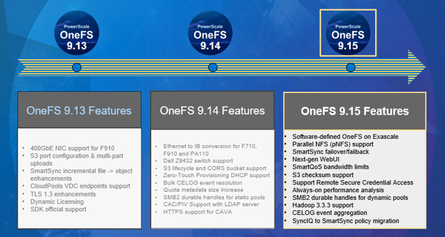
Dell PowerScale is kicking off the summer with the release of OneFS 9.15, introduced on August 11, 2026, marking a significant evolution of its scale-out NAS platform. This release brings broad innovation across platform capabilities, performance, security, serviceability, and ease of use, delivering meaningful value for a wide range of enterprise workloads.

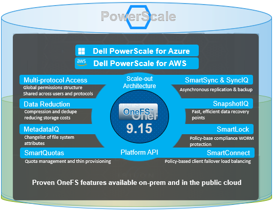
As the latest version of PowerScale’s unified software platform for both on-premises and cloud deployments, OneFS 9.15 is well suited for traditional file services, vertical industry use cases such as media and entertainment, healthcare, life sciences, and financial services, as well as modern workloads including generative AI, machine learning, deep learning, and analytics.

PowerScale continues to provide flexible deployment options across core, edge, and cloud environments, whether on-site, in colocation facilities, or through customer-managed deployments in AWS and Microsoft Azure. Its scale-out architecture ensures the performance and agility required to support increasingly complex unstructured data workflows. In today’s environment, where data security, threat detection, and operational visibility are more critical than ever, OneFS 9.15 introduces a slew of new capabilities and enhancements designed to strengthen performance, resiliency, and security while simplifying operations.

Performance enhancements are a central highlight of OneFS 9.15, including the general availability of pNFS, which enables parallel client data access and significantly improves throughput for AI and high-performance computing workloads.

With 9.15 also comes the introduction of software-defined OneFS on Dell Exascale, decoupling the PowerScale file system software from proprietary hardware, enabling flexible deployment on industry-standard servers and cloud infrastructure. This approach delivers the same enterprise-grade data services, scalability, and performance as traditional PowerScale appliances while providing greater deployment flexibility and cost efficiency for large scale AI environments.

Exascale, Dell’s rack-scale AI and data platform, uses AMD EPYC–based nodes and NVMe-rich storage behind 400Gb-class fabrics for massive AI training bandwidth. In addition to PowerScale, the Exascale platform can also be configured to natively run ObjectScale, Lightning file system, or PowerStore block.

OneFS 9.15 also delivers predictable, linear scaling across clusters ranging from 3 to 32 nodes, allowing organizations to grow efficiently without overprovisioning. SmartQoS has been enhanced with support for both bandwidth- and IOPS-based limits, separation of read and write workload classes, improved latency observability, and the ability to define system pools that isolate performance-sensitive nodes, providing administrators with granular control over resource allocation.

Security and compliance have also been strengthened through validation of cryptographic entropy sources for FIPS 140-3 compliance and updates to the secure development lifecycle, including removal of outdated software components and adoption of current packages to maintain a strong security posture. Reliability improvements are deeply embedded across the platform, with enhancements to the non-disruptive upgrade framework that improve stability, introduce retry mechanisms, and streamline upgrade operations. Additional resiliency gains include better service startup handling, continuous performance data collection through Always-On Performance Analysis, and optimizations for large file workflows and deduplication consistency.

Serviceability and observability see major gains with automated CELOG event aggregation, which correlates and enriches events to provide clearer insights and reduce troubleshooting time. Administrators also benefit from API-driven configuration management that eliminates the need for root access when adjusting advanced settings, along with automated diagnostic tools that generate actionable reports and proactive alerts for job failures or cancellations.

Finally, data mobility and user experience are further enhanced through the transition from SyncIQ to SmartSync, enabling more modern and flexible disaster recovery strategies while preserving existing investments. A new SmartSync web interface simplifies management, while improvements to SMB2 failover durability and expanded SmartQoS visibility enhance both resilience and operational clarity.

Theme Key Features
Unlock Platform Power for Gen AI ·         Exascale – Performance, reliability, compression

·         NVIDIA CX8 VPI network controller support

·         PowerScale switch DNOS 10.6.1.1 support

·         Enable SONiC on S5224 for TOR

File/Object Handling Enhancements ·         New checksum support for S3

·         Support for CRC64NVME default AWS checksum algorithm

·         Hadoop release 3.3.3 support

·         pNFS General Availability

·         Ability to force a dump of S3 server logs

Performance Improvements ·         Support for read, write and op classes as SmartQoS metrics

·         SmartQoS bandwidth limits

·         Linear Performance Scaling

·         Configurable system pool

Reliability ·         NDU hook framework stability, resilience, and performance enhancements

·         S3 service start up and non-disruptive config reload enhancements

·         Automated management for user configuration changes

·         Always On Performance Analysis

·         Cluster resiliency for large client workloads

·         Large file performance improvements

·         File metrics included in ‘isi statistics workload’ reporting

Serviceability ·         Aggregate CELOG event details for better customer experience

·         Remote Secure Credential (RSC) Access Enablement

·         Ability to alert when multiple jobs have cancelled/failed

·         Improved Performance diagnostics for Protocols

Data Mobility and Data Recovery ·         SmartSync DR – FO/FB – Moves across domains

·         Migration of SyncIQ policies to SmartSync

Useability ·         Enhanced WebUI Dashboard/Node Overview

·         Dynamic licensing subscription model for software-defined PowerScale on the Exascale platform

·         Directory Rename in PowerScale Cluster to reflect in ElasticSearch via Metadata IQ

·         SmartSync: WebUI for SmartSync

·         SMB 2 Durable handles for Dynamic Pools

·         Enhance latency metric for SmartQoS

·         Job engine reports.db size under control

Security ·         Cluster join rule enforcement update

·         OpenSSL support for FIPS 140-3

Overall, OneFS 9.15 reinforces Dell PowerScale’s position as a leading platform for unstructured data, delivering powerful advancements in scalability, performance, security, and operational efficiency, and equipping organizations to meet the growing demands of modern data-driven environments.

We’ll be taking a deeper look at the new OneFS 9.14 features and functionality in blog articles over the course of the next few weeks. Meanwhile, the new OneFS 9.15 code is available on the Dell Support site, as both an upgrade and reimage file, allowing both installation and upgrade of this new release.

For existing clusters running a prior OneFS release, the recommendation is to open a Service Request with to schedule an upgrade. To provide a consistent and positive upgrade experience, Dell Technologies is offering assisted upgrades to OneFS 9.15 at no cost to customers with a valid support contract. Please refer to this Knowledge Base article for additional information on how to initiate the upgrade process.

OneFS Zero Touch Provisioning DHCP Support

Standing up a new PowerScale cluster has always required a human armed with a serial cable. Before a node can join a cluster and receive a routable IP address through the standard network management path, an administrator must physically connect to the node’s serial console and manually configure the front-end network interface. For environments deploying a handful of nodes occasionally, this is a minor inconvenience. For large-scale datacenter deployments — where dozens or hundreds of nodes may need to be provisioned at once — the serial console dependency becomes a meaningful operational bottleneck, requiring scheduled on-site time from qualified engineers for what is essentially a repetitive, low-complexity task.

In addition to time, serial provisioning is inherently sequential, potentially error-prone, and tricky to automate. Plus it typically involves coordination between the storage admin and whoever has physical access to the racks. In a hyperscale or rapidly growing environment, the time spent cabling and typing IP addresses into consoles is time that scales linearly with node count.

OneFS 9.14 takes another decisive step in the journey to PowerScale Zero Touch Provisioning (ZTP) via native DHCP support for a cluster’s front-end network interfaces. This enables nodes to obtain their network configuration automatically from a remote DHCP server, rather than requiring manual IP assignment at the serial console.

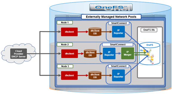
To appreciate ZTP’s benefits in OneFS 9.14, it helps to understand how OneFS already handles dynamic IP assignment in certain contexts. For several release now, OneFS has used an externally managed allocation method for network pools, backed by two SmartConnect components: The IP Reporter and the IP Merger.

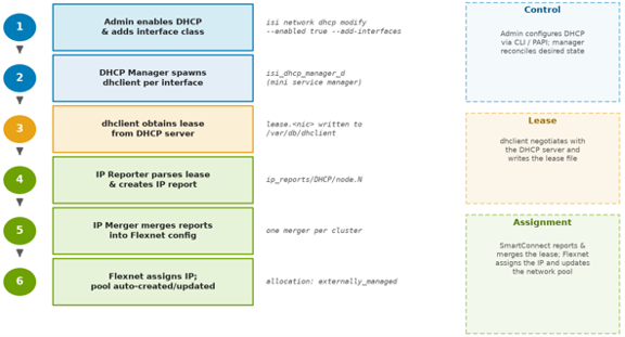
The IP Reporter parses external IP sources — such as DHCP lease files — and generates IP report files on the cluster filesystem (for example, /ifs/.ifsvar/modules/flexnet/ip_reports/DHCP/node.1). The IP Merger, which runs as a single instance per cluster, reads these reports and merges the discovered IP information into the Flexnet network configuration. Flexnet is the OneFS subsystem responsible for maintaining the authoritative view of which IPs are assigned to which interfaces on which nodes. Both components run on a fixed interval — roughly a one-minute cycle — so newly obtained leases are picked up automatically within a short window.

This SmartConnect-based path already exists and works in cloud deployments of OneFS, where DHCP is always enabled and the cloud provider’s DHCP server assigns IPs automatically. What was missing for on-premises deployments was the DHCP client management layer — the component responsible for actually running dhclient on the appropriate interfaces and producing the lease files that the existing IP Reporter can then parse. ZTP closes that gap with a new purpose-built daemon and a new cluster-level configuration surface, while deliberately reusing the proven IP Reporter/Merger pipeline rather than reinventing it.

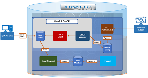
The new component introduced in OneFS 9.14 is ‘isi_dhcp_manager_d’, a daemon that runs on every node in the cluster.

Under the purview of MCP, the DHCP manager acts as a mini service controller, spawning and supervising one dhclient process per configured front-end interface. It monitors these processes for health, and continuously compares which interfaces should have DHCP and which nodes are excluded against the actual state (i.e. which dhclient processes are currently running) and corrects any drift. If an interface is added to the included list, the manager starts a client for it, and if one is removed or a node is excluded, the manager stops the corresponding client. This declarative model is what allows the same configuration to be safely re-applied across reboots, upgrades, and transient interface flaps without the need for manual intervention.

The end-to-end flow works as follows. The network administrator uses the CLI or PAPI to configure DHCP for the cluster. The DHCP Manager reads that configuration from Flexnet and starts a dhclient process on each included interface — for example, interface class ext-2 mapped to the physical NIC on a given node. Each dhclient negotiates with the DHCP server and writes a lease file to /var/db/dhclient/lease.<nic>. The DHCP Manager log consolidates the output from every dhclient it spawns into a single file, which makes debugging the DHCP protocol exchange considerably easier. The existing IP Reporter detects the lease, parses the assigned address, and writes an IP report; the IP Merger then merges it into the Flexnet configuration, and the Flexnet daemon performs the actual IP assignment to the interface.

Importantly, IPs remain assigned and tracked by Flexnet throughout, with ‘dhclient’ creating only the lease file. DHCP-obtained addresses show an allocation method of ‘externally_managed’, distinguishing them from statically assigned IPs. The DHCP Manager does not start or terminate dhclient for interfaces that are not link-up, and it automatically terminates any orphaned dhclient processes it finds running at startup.

One of the more useful behaviors demonstrated in ZTP is automatic network pool management. When a DHCP-assigned IP arrives, OneFS checks for an existing network pool covering that IP range. If one exists, the new IP is added to it, otherwise a pool is created automatically, along with the DHCP-obtained IP range is associated with it. The naming convention is of the general ‘groupnet0.subnet0.pool_dhcp’ format. As additional nodes obtain leases, their addresses are merged into the same pool’s IP ranges.

Critically, DHCP coexists with existing allocation methods on the same interface. An interface class such as ext-1 that already carries a statically assigned IP can also be enrolled in DHCP and receive an additional DHCP-assigned address. The result is an interface that holds both a static IP and a DHCP IP simultaneously, associated with multiple pools. This flexibility means DHCP can be layered onto an existing statically configured cluster without displacing any current addressing. This is an important property for brownfield environments, where removing a working static configuration to adopt DHCP would likely be a non-starter.

Zero Touch Provisioning in OneFS 9.14 introduces three configurable dimensions for DHCP management:

Capability Description
Enable or disable DHCP cluster-wide A single toggle governs whether DHCP is active across the cluster.
Specify which interface classes participate Admins define an ‘included’ list of interface classes that should be managed via DHCP.
Exclude specific nodes Individual nodes can be added to an ‘excluded’ list by Logical Node Number (LNN). assigned IPs remain untouched. This is useful when specific nodes have static requirements or when rolling DHCP out incrementally.

A single toggle governs whether DHCP is active across the cluster. DHCP is disabled by default on both fresh installs and upgrades from earlier OneFS versions, so existing deployments are never affected unless an administrator explicitly opts in. When disabled, the ‘isi_dhcp_manager_d’ service is present but not running.

Administrators define an ‘included’ list of interface classes (ie. ext-1, ext-2, mgmt-1) that should be managed via DHCP. Interfaces not in the list keep their existing allocation method.

Individual nodes can be added to an ‘excluded’ list by Logical Node Number (LNN). An excluded node will not run dhclient for any interface class regardless of the included list, and any DHCP-obtained IPs on that node are removed — while its statically assigned IPs remain untouched. This is useful when specific nodes have static requirements or when rolling DHCP out incrementally.

All DHCP configuration lives under the ‘isi network dhcp’ CLI command family, which supports both ‘view’ and modify ‘options’. The general configuration flow is as follows:

The following CLI commands can be used to configure and manage DHCP. For example, to view current state:

# isi network dhcp view

To enable DHCP cluster-wide:

# isi network dhcp modify --enabled true

To enroll interface classes, for example external and management interfaces:

# isi network dhcp modify --add-interfaces ext-1,ext-2

To remove an interface class:

# isi network dhcp modify --remove-interfaces ext-2

To exclude a node (for example LNN 4):

# isi network dhcp modify --add-excluded-nodes 4

To disable DHCP entirely:

# isi network dhcp modify --enabled false

Any modification triggers an interactive confirmation prompt — a safeguard against accidentally severing front-end connectivity if DHCP is the only IP source:

# isi network dhcp modify --enabled false
You are modifying DHCP settings. Please ensure you have front-end
connectivity via other statically/dynamically assigned IPs as you
may lose connectivity. Would you like to proceed? (yes/[no]):

The ‘–force’ flag can be added to suppress this prompt for scripted workflows. The same functionality is exposed through the PAPI at /platform/25/network/dhcp for orchestration tooling, and the DHCP configuration is captured hourly as telemetry via that endpoint.

When DHCP is disabled, the DHCP Manager terminates every dhclient process, removes the DHCP-obtained leases, and gracefully shuts down the daemon itself. Two pieces of state intentionally persist, however. First, the included-interfaces and excluded-nodes configuration is not cleared — so re-enabling DHCP later reapplies the previous configuration without re-entry. Second, any auto-created pool is not deleted; it remains (with no IP ranges) and is reused under the same name when DHCP IPs return within the same subnet. This persistence is a deliberate convenience: it means disabling DHCP is a reversible, low-friction operation rather than a destructive one.

Aspect Cloud On-Premises
Default state Always enabled, not configurable Disabled by default, admin-configurable
DHCP management MCP manages dhclient directly isi_dhcp_manager_d daemon manages dhclient
DHCP server Cloud provider managed Customer network managed
Node exclusion Not applicable Supported via LNN excluded list

Note that while cloud deployments already rely on DHCP, they do not yet take advantage of this new configuration surface or daemon — bringing the two models together is planned for a follow-up release.

When DHCP-assigned IPs are not appearing as expected, the following systematic diagnostic sequence will usually cover the most common failure points:

Step CLI Command Expected Result
DHCP enabled? isi network dhcp view Enabled: True
Node not excluded? isi network dhcp view Node LNN absent from Excluded Nodes list
Service running? isi services -a isi_dhcp_manager_d Service reported as enabled
dhclient active? ps aux | grep dhclient One dhclient: <nic> per configured interface
Lease file present? ls /var/db/dhclient/ lease.<nic> present per interface
IP bound to interface? ifconfig <nic> | grep inet inet <ip-address> present

A good approach is generally to work through the above checklist from top to bottom, with each step gating the next. If DHCP shows disabled or the node appears in the excluded list, nothing downstream will happen by design. If the service is enabled but no dhclient is running, the interface’s link may not be up, or the interface class may not be in the included list. If dhclient is running but no lease file appears, the issue is almost certainly between the node and the DHCP server (reachability, scope exhaustion, or relay configuration). And if a lease exists but no IP is bound, the bottleneck is typically the IP Reporter/Merger cycle or a pool conflict during the merge.

The principal log file locations include:

Log file Detail
/var/log/isi_dhcp_manager_d.log Primary daemon log, including consolidated dhclient output.
/var/log/isi_smartconnect IP Reporter and IP Merger logs covering lease parsing and pool merging.
/var/db/dhclient/lease.<nic> Raw lease files, confirming what the DHCP server offered.
/ifs/.ifsvar/modules/flexnet/flx_config.xml Stored DHCP configuration as seen by Flexnet


There are also three new DHCP-related CELOG events flags introduced in OneFS 9.14 in support of ZTP:

Event Severity Meaning / Action
SW_SC_DHCP_CLIENT_RESTART Warning dhclient restarted 5+ times in 15 min — check network stability and DHCP server availability
SW_SC_IPMERGE_FAILED Warning DHCP IP could not be merged into Flexnet (e.g., address already in a static pool) — check for IP pool conflicts or invalid pool configuration
SW_SC_DHCP_LEASE_REBIND Critical Lease renewal failed, IP at risk of expiring — verify DHCP server is reachable

With OneFS 9.14’s ZTP capability, on-prem PowerScale nodes can now receive their front-end network addresses from a DHCP server automatically, without serial console access during provisioning. Built on the existing SmartConnect IP Reporter and Merger infrastructure, the new isi_dhcp_manager_d daemon slots cleanly into the Flexnet pipeline, auto-creating network pools, allowing static and DHCP addresses to coexist on the same interface, and preserving configuration across enable/disable cycles — all without displacing any existing IP allocation mechanism. Removing the requirement for serial console access from the provisioning path helps set the stage for broader zero-touch deployment automation in future releases.

OneFS Automated Syslog Rule Configuration

In this article, we’ll take a look at one of the quieter but genuinely useful serviceability enhancements that arrives with the OneFS 9.14 release: REST API access for creating and updating syslog rules. Delivered under capability 5512, this feature brings the cluster’s logging configuration into the same programmatic, automation-friendly world that storage admins increasingly expect from the rest of the platform

Before digging into what’s new, it’s worth a brief recap of what syslog actually does. Syslog is the ubiquitous standard that devices and applications use to ship event logs to a central location. On a PowerScale node, the syslog daemon receives log messages from the operating system and its various services through its sockets, and then routes each message to the appropriate destination: a local log file, or a remote log server.

Those routing decisions are governed by rules. Each message is tagged with a facility – the subsystem it originated from, such as auth, mail, kern, or daemon – and a severity level, running from debug all the way up to emergency. A syslog rule is essentially a filter-plus-destination pairing: messages from a given facility, at a given severity or above, are sent to a particular destination. On OneFS, as on most BSD-derived systems, these rules live in the /etc/syslog.conf file, which the daemon reads and evaluates at runtime.

Centralized, well-routed logging matters for more than just day-to-day troubleshooting. It underpins security monitoring, forensic investigation, and the audit trails that many compliance regimes mandate – which is precisely why reliably forwarding the right messages to the right collector is something operations teams care about getting right. It’s a simple, battle-tested model; the friction has always been in how you manage it.

Historically, configuring syslog rules on a cluster involved editing system files directly. To add a rule that forwarded authentication events to a security information and event management (SIEM) collector, for example, you’d open syslog.conf, hand-craft the appropriate selector and action lines, save the file, and validate the result manually. That approach works, but it carries a familiar set of problems:

  • Error-prone – hand-editing configuration files is exactly the kind of task where a stray tab, a typo in a facility name, or a malformed destination quietly breaks logging, often in ways you don’t notice until you go looking for logs that were never written.
  • Operational overhead – every change is a manual, repeated sequence of steps, and every cluster has to be touched individually.
  • Inconsistent setups – without a programmatic source of truth, it’s hard to guarantee that twenty clusters share the same logging policy, and configuration drift inevitably creeps in.
  • Poor automation support – manual file edits don’t slot neatly into the Infrastructure-as-Code and DevOps pipelines that modern operations teams build everything else around.

For a single cluster managed by one administrator, none of this is fatal. At scale, it becomes a genuine source of toil and risk.

OneFS 9.14 addresses this by exposing syslog configuration through the OneFS Platform API (PAPI). Rather than editing files, you now create, update, and delete syslog rules – including rules that forward to remote servers – through a documented, versioned REST interface. The benefits are exactly what you’d expect from moving any configuration surface from files to an API:

  • Programmatic configuration that can be scripted and version-controlled.
  • Seamless integration into existing automation workflows, whether that’s a provisioning script, a configuration-management tool, or a CI/CD pipeline.
  • Consistency and repeatability, so the same policy can be applied identically across every cluster in the estate.
  • Easier maintenance, because the API enforces structure rather than relying on free-form text.

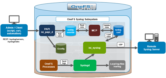
Under the covers, the flow is straightforward. A client (i.e. a script, automation tool, or a simple curl one-liner) issues a request to the PAPI endpoint.

The platform API daemon, isi_papi_d, validates the request and translates it into the corresponding change in the syslog configuration. OneFS’s Master Control Program (MCP) is then responsible for propagating that configuration consistently across the nodes of the cluster, and the syslog daemon, isi_syslogd, picks up the updated rules and begins routing messages accordingly.

The key thing to note is that the API operates on the canonical configuration. There’s no risk of the API view and the on-disk configuration diverging, because the API is the thing writing the configuration. And because MCP handles distribution, a rule you create once is applied cluster-wide rather than node-by-node – which is precisely the consistency guarantee that hand-editing files on individual nodes could never offer.

The syslog auto rule functionality introduces two new endpoint groups. The first, /syslog/servers, manages the definition of remote syslog destinations, while the second, /syslog/rules, manages the rules themselves:

GET    /platform/<ver>/syslog/servers      # list configured remote servers
POST   /platform/<ver>/syslog/servers      # define a new remote server
DELETE /platform/<ver>/syslog/servers/<id> # remove a remote server

GET    /platform/<ver>/syslog/rules        # list API-created rules
POST   /platform/<ver>/syslog/rules        # create a new rule
DELETE /platform/<ver>/syslog/rules/<id>   # remove a rule

The division of responsibility is clean: The remote collectors are registered once via /syslog/servers, and then referenced when creating forwarding rules via /syslog/rules. A rule can forward matching messages to one of two kinds of destination – a local log file (restricted, sensibly, to the /var/log directory), or a remote syslog server that has been previously defined through the servers endpoint.

That /var/log restriction is worth calling out. By constraining local destinations to /var/log, OneFS avoids a whole class of problems in which a misconfigured rule could write log data into arbitrary – and potentially sensitive or space-constrained – areas of the filesystem. It’s a small guardrail, but a sensible one.

A typical sequence to forward authentication logs to a central collector breaks down into two steps. First, the remote server is registered through /syslog/servers, giving OneFS the address – and, depending on your environment, the transport and port – of the collector you want to ship logs to. Then, create a rule through /syslog/rules that selects the facility and severity you care about (authentication messages at, say, informational level and above) and points them at the server you just registered.

Removing the configuration later is the mirror image: delete the rule, then delete the server definition once nothing else references it. Listing is a simple GET against either endpoint, which makes the API equally valuable for auditing – you can ask a cluster what syslog rules it actually has, programmatically, rather than parsing a configuration file and hoping you read it correctly.

Because every one of these operations is a REST call, the whole sequence can be wrapped in a script and applied uniformly across as many clusters as you like. That is the entire point of the capability: the same logging policy, defined once, applied everywhere, with no text editors and no drift.

When investigating or troubleshooting syslog issues, there are a handful of places to look. To confirm that the syslog daemon itself is healthy, first check its service status:

# isi service isi_syslogd status

If an API call isn’t producing the configuration you expect, the platform API daemon’s log is the first stop, since that’s where request handling and validation are recorded:

# less /var/log/isi_papi_d.log

And because MCP is responsible for distributing the configuration across the cluster, its logs are the place to look if a change appears to have been accepted but has not been applied consistently:

# less /var/log/isi_mcp

Between the three – the daemon’s health, the API request log, and the MCP distribution log – you can usually pinpoint whether an issue lies in the request, in its propagation, or in the service itself.

In summary, the automated syslog rule configuration capability in OneFS 9.14 is a modest-sounding change with an outsized practical impact for anyone running PowerScale at scale. By exposing syslog server and rule management through the Platform API, OneFS turns what used to be a manual, error-prone, file-editing chore into a clean, scriptable, repeatable operation. Remote forwarding to a SIEM or central log server becomes a couple of API calls; auditing a cluster’s logging policy becomes a single GET; and rolling the same configuration out across an entire fleet becomes a loop in a script. So, for organizations standardizing on Infrastructure-as-Code, it removes one more manual island from the management plane. Plus, for everyone else, it simply makes a tricky task quicker, safer, and more easily and accurately repeatable.

OneFS S3 CORS Support

Modern web applications routinely load resources — images, videos, fonts, scripts — from origins other than the server hosting the page. Browsers enforce the ‘same-origin policy’ by default, which blocks these cross-origin requests unless the target server explicitly permits them. Cross-Origin Resource Sharing (CORS) is the W3C mechanism that provides those permissions, and as of OneFS 9.14, PowerScale S3 supports it natively on a per-bucket basis.

This capability matters for any organization running a web application that reads from or writes to a PowerScale S3 bucket directly from a browser. Without CORS configuration on the bucket, the browser silently blocks the request at the network layer — no error in the server logs, just a failed request on the client side. A CORS policy tells the browser which origins, HTTP methods, and headers are acceptable, enabling seamless integration between frontend applications and PowerScale object storage while preserving the bucket’s underlying access controls.

Web browsers enforce a same-origin policy that, by default, prevents a web application served from one origin (a combination of scheme, host, and port) from reading resources served from a different origin. CORS relaxes this policy in a controlled manner. By using a defined set of HTTP response headers, a resource declares which other origins, HTTP methods, and request headers are permitted to access it.

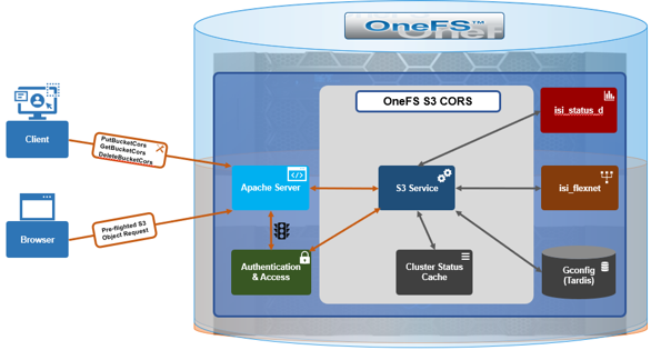
Before sending a cross-origin request that could have side effects — such as a PUT or DELETE — the browser sends an HTTP OPTIONS preflight request to the target server. The preflight carries:

  • Origin — the domain making the request
  • Access-Control-Request-Method — the HTTP method the browser intends to use
  • Access-Control-Request-Headers — any non-standard request headers

The S3 service evaluates these headers against the bucket’s CORS configuration and returns the appropriate Access-Control-* response headers. If all three are permitted by a matching rule, the browser proceeds with the actual request. If any one is rejected, the browser aborts. For simple read-only requests (GET, HEAD) the browser skips the preflight and reads the CORS response headers from the actual response directly.

CORS support extends OneFS S3 to browser-based workloads that would otherwise be blocked by the same-origin policy. Consider, for example, a website which needs to load images and other assets from a PowerScale S3 bucket. Without a CORS configuration the browser blocks these requests. Once CORS is configured to allow the application’s origin, the assets are retrieved and displayed successfully. Similarly, workflows where users upload files directly to a PowerScale S3 bucket from a front-end application, with no back-end proxy server in the request path. Once the bucket permits the application’s origin, uploads succeed and the browser receives a valid response with no CORS errors.

OneFS 9.14 introduces three new S3 API operations for managing per-bucket CORS configuration, and extends all existing bucket and object APIs with CORS response headers.

The CORS configuration is attached to an individual bucket and defines one or more rules. Each rule declares the allowed origins, HTTP methods, request headers, response headers to expose, and how long a browser may cache a preflight result.

1.       PutBucketCors

PutBucketCors sets a CORS configuration on a bucket. If a configuration already exists it is replaced in full — there is no partial update. The request body is an XML document:

<?xml version="1.0" encoding="UTF-8"?>
<CORSConfiguration xmlns="http://s3.amazonaws.com/doc/2006-03-01/">
  <CORSRule>
    <ID>allow-webapp</ID>
    <AllowedOrigin>https://app.example.com</AllowedOrigin>
    <AllowedMethod>GET</AllowedMethod>
    <AllowedMethod>PUT</AllowedMethod>
    <AllowedHeader>*</AllowedHeader>
    <ExposeHeader>ETag</ExposeHeader>
    <MaxAgeSeconds>3600</MaxAgeSeconds>
  </CORSRule>
</CORSConfiguration>

A bucket can have multiple CORSRule blocks, each scoped to a different origin or method set. MaxAgeSeconds controls how long the browser may cache the preflight response, reducing round trips for repeat requests. Table 1 describes the CORS rule elements.

Element Description
AllowedOrigin One or more origins from which cross-origin requests
are allowed. A single wildcard (*) is permitted.
AllowedMethod An HTTP method the origin is allowed to use.
Valid values:GET,PUT,HEAD,POST,DELETE.
AllowedHeader A request header allowed in a preflight request viaAccess-Control-Request-Headers. A trailing wildcard (*)
is permitted.
ExposeHeader A response header that the browser is allowed to expose
to the client application.
ID An optional unique identifier for the rule.
MaxAgeSeconds The time in seconds that the browser may cache the
preflight response for the requested resource.

Required permission: Bucket owner or FULL_CONTROL ACL on the
bucket. Using the AWS CLI against a PowerScale endpoint:

aws s3api put-bucket-cors \
  --bucket mybucket \
  --cors-configuration file://cors.json \
  --endpoint-url https://powerscale.example.com:9020

2.       GetBucketCors

GetBucketCors returns the current CORS configuration for a bucket:

GET /<bucket>?cors

The response returns the same XML structure set by PutBucketCors. If no CORS configuration exists, the API returns 404 NoSuchCorsConfiguration.

Required permission: Bucket owner or READ ACL.

aws s3api get-bucket-cors \
  --bucket mybucket \
  --endpoint-url https://powerscale.example.com:9020

3.       DeleteBucketCors

DeleteBucketCors removes the CORS configuration from a bucket entirely:

DELETE /<bucket>?cors

After deletion the bucket returns no CORS headers and browser cross-origin requests will fail. There is no versioning, so the configuration is gone immediately.
Required permission: Bucket owner or FULL_CONTROL ACL.

The other new S3 operation introduced in OneFS 9.14 is the HTTP OPTIONS method, which browsers send as a preflight check before a cross-origin request that could have side effects. OneFS evaluates the preflight entirely outside the normal S3 authentication path, with no credentials required:

OPTIONS /<bucket>/<object> HTTP/1.1
Origin: https://app.example.com                  # origin url, including scheme and port
Access-Control-Request-Method: PUT               # intended http method
Access-Control-Request-Headers: Content-Type     # non-standard request headers

OneFS compares the origin, method, and headers against the bucket’s CORS rules and responds with the appropriate ‘Access-Control-*’ headers. Authentication is bypassed for ‘OPTIONS’ by design, consistent with the S3 specification, since the browser sends the preflight before it has any context for signing the subsequent request.

In addition to the three new CORS operations, all existing bucket-level and object-level S3 APIs now return CORS response headers on 200 OK responses where the request matches a configured rule. Three bucket-level APIs (HeadBucket, PutBucket/CreateBucket, and DeleteBucket) are intentionally excluded, consistent with Amazon S3 behavior.

Response Header Description
Access-Control-Allow-Origin The origin permitted to access the
resource, echoed from the matched rule, or a wildcard (*).
Access-Control-Allow-Methods The HTTP methods permitted for the
matched origin.
Access-Control-Allow-Headers The request headers permitted in the
actual cross-origin request.
Access-Control-Expose-Headers The response headers the browser is
allowed to expose to the client application (e.g.ETag).
Access-Control-Max-Age How long in seconds the browser may cache
the preflight response.
Access-Control-Allow-Credentials Whether the response may be exposed
when the request’s credentials mode is set.

CORS support requires no additional cluster-level configuration. The feature becomes active once the S3 service is enabled on the cluster:

# isi s3 settings global modify --service enabled

A CORS rule applies to a bucket only after a client sets a configuration with PutBucketCors. Until then, the bucket enforces the browser’s default same-origin behavior. On upgrade, the feature is applied after the upgrade is committed. After uninstallation the feature no longer functions.

When investigating and troubleshooting S3 CORS, the most common issues typically fall into three categories:

  • CORS configuration management errors
  • OPTIONS preflight errors
  • Rule matching failures.

1. CORS Configuration Management Errors

These occur when calling PutBucketCors, GetBucketCors, or DeleteBucketCors directly, typically because the supplied XML is malformed, the caller lacks the required ACL, or no configuration has been set yet:

Status Error Cause Resolution
400 Bad Request Incorrect CORS configuration XML Check the error message and fix the configuration issue
403 Forbidden Caller lacks required bucket ACL FULL_CONTROL for Put/Delete, READ for Get; must be bucket owner
404 NoSuchCorsConfiguration No CORS config set on the bucket CallPutBucketCorsfirst

2. OPTIONS Preflight Errors

These are returned when the browser’s preflight request is missing one of the two required headers that OneFS needs to evaluate the request against the bucket’s CORS rules:

Status Error Cause Resolution
400 InvalidRequest OPTIONS preflight missingOriginorAccess-Control-Request-Method Both headers are required in every preflight request

3. Rule Matching Failures

These are the most frequent issues in practice. The bucket has a CORS configuration but the incoming request does not satisfy any rule, either because no configuration exists at all, or because the origin, method, or headers are not listed as permitted. CorsNotAllowed is the most common: AllowedOrigin values are matched exactly, so https://app.example.com and https://app.example.com:443 are treated as different origins. Wildcards (*) are supported in AllowedOrigin and AllowedHeader but not in AllowedMethod:

Status Error Cause Resolution
403 CorsNotEnabled No CORS configuration on the bucket CallPutBucketCorsto define at least one rule
403 CorsNotAllowed Origin, method, or headers not matched by any configured rule Review the CORS rules; confirmAllowedOriginmatches exactly
(scheme + host + port)

In summary, PowerScale S3 CORS support in OneFS 9.14 adds three new S3 APIs, PutBucketCors, GetBucketCors, and DeleteBucketCors, plus the OPTIONS preflight handler. CORS response headers are also returned upon the successful responses of all existing bucket and object operations where a matching rule exists.

Configuration is per-bucket, requires no additional licensing, and takes effect immediately after PutBucketCors is called. The implementation is compatible with standard AWS S3 SDK clients using the ‘–endpoint-url’ override, making it straightforward to integrate into existing web application stacks that already target Amazon S3.

OneFS Health Check Framework Automatic Update and Repair

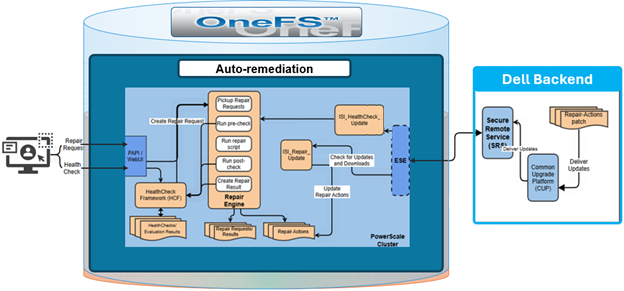
The OneFS Health Check Framework (HCF) has long provided a proactive way to monitor cluster health and surface potential issues before they affect data availability or performance. Behind the scenes, the framework periodically checks Dell’s Connectivity Hub portal for updated health check definition packages and repair action patches that have been assigned to the cluster, and when newer versions are found, automatically downloads and installs them without requiring any administrator involvement. For enterprise PowerScale environments in particular, this helps reduces maintenance overhead across large or geographically distributed deployments.

That said, the convenience of automatic updates is not universally applicable. Customers operating in regulated industries, high-security environments, or organizations with formal change management processes have consistently asked for the ability to control when and whether software components on their clusters are updated automatically. For these environments, having a patch silently installed — even a health check definition — can conflict with internal approval workflows, audit requirements, or network policies that restrict outbound connections to external systems. OneFS 9.14 addresses this directly with the introduction of independent controls for automatic download of health check definitions and repair action patches, giving administrators the ability to enable or disable each subsystem’s auto-update behavior without disabling the Health Check Framework itself.
Before looking at the new controls, it helps to understand the existing auto-update flow.

When Dell releases an updated health check definition package or a new repair action patch, it is made available through the Connectivity Hub portal and can be assigned to specific clusters. Once assigned, the cluster’s auto-update scripts, ‘isi_healthcheck_update’ for health check definitions and ‘isi_repair_update’ for repair actions, detect the new version on their next scheduled execution and proceed to download and install the update.

These scripts are the enforcement point for the new configuration, via gconfig control parameters, that the update scripts consult before taking any action. If auto-update is disabled for a given component when the script runs, the script exits cleanly without downloading or installing anything, even if a newer version has been assigned through the portal. This behavior is consistent whether the scripts are triggered by a scheduled job or invoked manually, so there are no edge cases where a manually triggered update bypasses the administrator’s preference.

The new configuration controls follow the same layered architecture used throughout OneFS for platform settings. Both the webUI and the CLI leverage the underlying platform API, which route requests to the Health Check Auto Update Handler and the Repair Settings Handler. Each handler exposes a PUT API endpoint that writes the relevant configuration values into the gconfig tree under the healthcheck and repair subtrees respectively. The update scripts then read these values at runtime to determine whether to proceed with the download and install.

This architecture means there is no change to how assignments are managed through the Connectivity Hub, and no change to how the scripts themselves are scheduled. The only difference in behavior is gated entirely by the gconfig values that the new API surfaces expose.

The new HCF functionality introduces independent controls for two distinct subsystems:

Subsystem Details
Health Check Definitions The check packages that define what the HCF tests on the cluster. Auto-update for health check definitions is enabled by default, meaning clusters running OneFS 9.14 or later will continue to receive updated check packages automatically unless this setting is explicitly disabled.


Repair Actions Automated remediation procedures that can be applied when a health check identifies a problem. The repair service itself is disabled by default in OneFS, and its auto-update setting is also disabled by default. Both must be explicitly configured before any repair-related automatic updates will occur.


The separation between these two controls is intentional, allowing a cluster admin who wishes the cluster to always run the latest health checks, while maintaining tighter control over automated remediation, to leave health check auto-update enabled and keep repair auto-update disabled. Alternatively, an environment that prefers to fully lock down all automatic software changes can disable both.

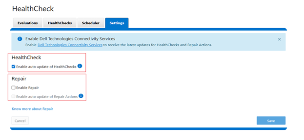
Within the OneFS 9.14 WebUI, the new settings appear under Cluster management > HealthCheck > Settings  as two separate checkboxes:

  • Auto update for health checks— enabled by default
  • Auto update for repair actions— disabled by default

The repair actions checkbox is inactive (grayed out) until the repair service has been separately enabled. Attempting to toggle the repair auto-update setting before enabling the service generates an error indicating that auto-update settings can only be modified when the repair service is active.

These configuration options are also available from the CLI. For example, to disable automatic download of health check definitions from its default enabled state:

# isi healthcheck settings modify --enabled false

And similarly to re-enable it again:

# isi healthcheck settings modify --enabled true

For repair actions, the configuration is a two-step process. First, the repair service must be activated since it is disabled by default:

# isi repair settings modify --repair-enable true

Once the repair service is running, its auto-update behavior can be configured:

# isi repair settings modify --auto-update-enable true

Attempting to set –auto-update-enable without first enabling the repair service will fail with an error. The default value for repair auto-update is false, so simply enabling the repair service does not by itself turn on automatic patch downloads — that remains an explicit opt-in.

To check the currently installed version of repair actions on the cluster:

# isi repair settings view

   Repair Behavior: auto

    Repair Enabled: Yes

Autoupdate Enabled: No

This is useful when verifying that a manually initiated update completed successfully, or when confirming the current baseline before scheduling a maintenance window for a controlled update.

Access control and security-wise, two separate RBAC privileges govern these settings:

Action Privilege
Health check configuration Requires the ISI_PRIV_SYS_SUPPORT privilege.
Repair configuration Requires the ISI_PRIV_REPAIR privilege.

In addition to privileges, there are cluster-state security restrictions that take precedence over the gconfig settings. As such, the automatic download functionality is suppressed entirely when the cluster is operating in any of the following elevated security or transitory states:

  • Compliance mode
  • Hardening mode (STIG)
  • Root Lockdown Mode (RLM)
  • Upgrade pre-commit

In these modes, automatic downloads are blocked regardless of the configured auto-update values, ensuring that the cluster’s compliance posture cannot be undermined by a background update process. Note that the gconfig values will not change on clusters transitioning into or out of these modes — only the enforcement behavior changes based on cluster state — so the configured preferences will resume taking effect once the cluster exits the restricted state.

When investigating and troubleshooting auto-update behavior, typically the first diagnostic step is to inspect the relevant gconfig settings directly:

# isi_gconfig -t healthcheck

[root] {version:1}

healthcheck_autoupdate.enabled (bool) = true

healthcheck_autoupdate.compliance_update (bool) = false

healthcheck_autoupdate.alerts (bool) = false

healthcheck_autoupdate.max_download_package_time (int) = 600

healthcheck_autoupdate.max_install_package_time (int) = 3600

healthcheck_autoupdate.number_of_failed_upgrades (int) = 0

healthcheck_autoupdate.last_failed_upgrade_package (char*) =

healthcheck_autoupdate.download_directory (char*) = /ifs/data/auto_upgrade_healthcheck/downloads

This outputs all current health check configuration values, including the auto-update flag. Confirm that the value of the auto-update key reflects the intended setting.

For repair-related issues, a logical first step is to verify that the repair service itself is running:

# isi services –a isi_repair

Service 'isi_repair' is enabled.

If the repair service is not active, any attempt to modify auto-update settings will fail. The relevant gconfig settings can be inspected directly, as follows:

# isi_gconfig -t repair

[root] {version:1}

repair.repair_enabled (bool) = true

repair.repair_behavior (char*) = auto

repair.default_repair_time_limit (int) = 600

repair.autoupdate_enabled (bool) = false

repair.alerts (bool) = false

repair.max_download_package_time (int) = 600

repair.max_install_package_time (int) = 3600

repair.number_of_failed_upgrades (int) = 0

repair.last_upgrade_package (char*) =

Additionally, detailed logs from repair update operations are written to the /var/log/isi_repair.log, and provide granular detail on what occurred during a given update attempt. This info includes whether a remote file was found, whether the download completed, and whether installation succeeded.

Similarly, for health check updates, the ‘isi_healthcheck_update’ script writes to /var/log/ isi_healthcheck.log, the contents of which will indicate whether it exited early due to auto-update being disabled, or whether it proceeded to download and install a package.

OneFS HTTPS Support for CAVA Antivirus

OneFS 9.14 introduced HTTPS support for the Common AntiVirus Agent (CAVA), enhancing the existing scanning solution with secure communication between the PowerScale cluster and Dell Common Event Enabler (CEE) server and enabling operation in hardening mode.

CAVA a service that runs on the CEE server, often referred to as CEE‑CAVA. It receives file access requests from the CAVA client interface on OneFS (also known as OneFS‑CAVA) and attempts to access the specified file over SMB. During this process, the antivirus engine residing on the CEE server scans the file. If CEE‑CAVA can successfully access and scan the file without detecting any threats, it returns a response indicating that the file is not infected. Conversely, if a threat is identified or access conditions indicate an issue, it responds with a message indicating that the file is infected.

Prior to OneFS 9.14, communication between the OneFS‑CAVA agent and the CEE‑CAVA service was conducted over HTTP, which did not provide secure transport. As a result, CAVA was automatically disabled on clusters operating in hardening mode. However, customers have expressed a strong requirement to enable CAVA while maintaining compliance with hardening mode security standards.

CAVA HTTPS support requires CEE version 9.1.2 or later in conjunction with OneFS 9.14 or newer, while existing antivirus licensing continues to be sufficient.

Configuring and enabling CAVA with HTTPS entails the following high-level process:

Note that the CAVA over HTTPS capability only becomes available after the upgrade to OneFS 9.14 has been fully committed. Additionally, upgrading to OneFS 9.14 does not impact existing legacy scanning workflows that continue to use standard HTTP transport.

  1. Setup CA certificates

From the OneFS CLI, import the CA certificate(s) using its full path on the cluster:​

# isi antivirus cava certificates ca import --name=ca_unit --certificate-path=/ifs/certs/ca.pem​

Imported certificate: 4c6d3f0d1c3128ed09e02a78a1d9e3104edbfeb9c327c5e735afb3b48cd5bdbc​

​Once done, verify that the CA certificate was imported successfully:

# isi antivirus cava certificates ca list​

ID Name Not Before Not After Status​

--------------------------------------------------------------------------------------------------------------------------​

4c6d3f0d1c3128ed09e02a78a1d9e3104edbfeb9c327c5e735afb3b48cd5bdbc ca_unit 2025-08-28T07:39:22 2125-08-04T07:39:22 valid​

--------------------------------------------------------------------------------------------------------------------------​

Total: 1​

# isi antivirus cava certificates ca view 4c6d3f0d1c3128ed09e02a78a1d9e3104edbfeb9c327c5e735afb3b48cd5bdbc​

ID: 4c6d3f0d1c3128ed09e02a78a1d9e3104edbfeb9c327c5e735afb3b48cd5bdbc​

Name: ca_unit​

Status: valid​

Not Before: 2025-08-28T07:39:22​

Not After: 2125-08-04T07:39:22​

Description:​

Fingerprints​

Type: SHA1​

Value: f1:0e:34:d0:0c:65:99:b8:86:58:f3:b3:36:21:9a:64:7a:e6:b5:03​

Type: SHA256​

Value: 4c:6d:3f:0d:1c:31:28:ed:09:e0:2a:78:a1:d9:e3:10:4e:db:fe:b9:c3:27:c5:e7:35:af:b3:b4:8c:d5:bd:bc​

Subject: C=IN, ST=DCU, L=Gotham, O=Wayne Enterprises, OU=Batman, CN=batmanCA, emailAddress=batmanCA@bat.man​

Issuer: C=IN, ST=DCU, L=Gotham, O=Wayne Enterprises, OU=Batman, CN=batmanCA, emailAddress=batmanCA@bat.man​

​Or from the WebUI under Data Protection > Antivirus > CAVA, where OneFS 9.14 introduces a new Certificates section which includes three tabs: Authority, Identity, and Settings:

Users with the ‘ISI_PRIV_ANTIVIRUS’ RBAC privilege can manage CA and identity certificates, including performing operations such as ‘import’, ‘edit’, ‘replace’, and ‘delete’.

Import the certificate authority (CA) under Data Protection > Antivirus > CAVA > Certificates > Authority:

  1. Setup Identity Certificates

Next, import the identity certificate(s) as follows, specifying the full path to the cert and key files:​

# isi antivirus cava certificates identity import --name=onefs_cava --certificate-path=/ifs/certs/signed_id_cert.pem --certificate-key-path=/ifs/certs/id_cert.key --skip-certificate-passphrase​

Imported certificate: 70b6734399785ff5d512a789836bdf45e4ee35cf464e6da36d16cda5db6ef353​

Once complete, verify that the identity certificate was imported successfully:

# isi antivirus cava certificates identity list​

ID Name Not Before Not After Status​

---------------------------------------------------------------------------------------------------------------------------​

70b6734399785ff5d512a789836bdf45e4ee35cf464e6da36d16cda5db6ef353 onefs_cava 2026-01-21T13:51:12 2125-12-28T13:51:12 valid​

---------------------------------------------------------------------------------------------------------------------------​

Total: 1​

# isi antivirus cava certificates identity view 70b6734399785ff5d512a789836bdf45e4ee35cf464e6da36d16cda5db6ef353​

ID: 70b6734399785ff5d512a789836bdf45e4ee35cf464e6da36d16cda5db6ef353​

Name: onefs_cava​

Status: valid​

Not Before: 2026-01-21T13:51:12​

Not After: 2125-12-28T13:51:12​

Description:​

Fingerprints​

Type: SHA1​

Value: 79:68:ab:a2:5d:95:31:53:6c:90:a7:5c:99:d5:f7:95:a7:db:99:22​

Type: SHA256​

Value: 70:b6:73:43:99:78:5f:f5:d5:12:a7:89:83:6b:df:45:e4:ee:35:cf:46:4e:6d:a3:6d:16:cd:a5:db:6e:f3:53​

Subject: C=IN, ST=DCU, L=Gotham, O=Wayne, OU=Batman, CN=robinOnefs, emailAddress=robinOnefs@bat.man​

Issuer: C=IN, ST=DCU, L=Gotham, O=Wayne Enterprises, OU=Batman, CN=batmanCA, emailAddress=batmanCA@bat.man​

Or from the WebUI under Data Protection > Antivirus > CAVA > Certificates > Identity:

  1. Add CAVA server

Next, create the CAVA server configuration on the cluster:​

# isi antivirus cava servers create CAVA1 https://10.10.20.50:12443/cee --enabled 1​

​Once done, verify that the CAVA server was added successfully:

# isi antivirus cava servers list​

Server Name Server URI Enabled Server Type​

------------------------------------------------------------------​

CAVA1 https://10.10.20.50:12443/cee Yes CEE/CAVA​

------------------------------------------------------------------​

Total: 1​

​

# isi antivirus cava servers view CAVA1​

Server Name: CAVA1​

Server URI: https://10.10.20.50:12443/cee​

Enabled: Yes​

Server Type: CEE/CAVA​

​Or from the WebUI under Data Protection > Antivirus > CAVA > Servers:

Note that, when adding the server, specify protocol as https:// and port number in the URI​.

If needed, a CAVA server can also be removed with the following CLI syntax:

# isi antivirus cava servers delete CAVA1​
  1. Configure identity certificate ID and Enable TLS in CAVA global settings

The ‘–enforce-tls’ global configuration parameter is set to ‘false’ by default, permitting CAVA to use regular HTTP transport. By setting this flag to ‘true’, CAVA over HTTPS communication is enabled.

From the CLI:

# isi antivirus cava settings modify --enforce-tls=true --certificate-id=7ba9188a5f6bb120c8ea3e499b662b38319587804492cf444df02b33b1d4a86c​

​# isi antivirus cava settings view​

Service Enabled: Yes​

Scan Access Zones: System​

IP Pool: groupnet0.subnet0.cavapool​

Report Expiry: 8 weeks, 4 days​

Scan Timeout: 1 minute​

Cloudpool Scan Timeout: 1 minute​

Maximum Scan Size: 0.00kB​

Certificate ID: 7ba9188a5f6bb120c8ea3e499b662b38319587804492cf444df02b33b1d4a86c​

Enforce TLS: Yes​

Note that omitting the client certificate ID will result in the following error:

# isi antivirus cava settings modify --enforce-tls=true

TLS cannot be enabled as no client certificate ID is configured.

This can also be configured from the WebUI under Data protection > Antivirus > CAVA > Settings. Disabled by default, in order to activate this option, users must select an identity certificate, which is a prerequisite for enforcing TLS:

Note that attempts to activate TLS enforcement on a cluster without any identity certificates will generate the following pop-up warning:

This warning includes a link, which opens the identity certificate import and configuration portal.

Optionally add an OCSP server URI and set revocation mode:​

# isi antivirus cava certificates settings view​

OCSP Responder URI:​

OCSP Revocation Mode: None​

Strict Hostname Check: No​

# isi antivirus cava certificates settings modify --ocsp-responder-uri=http://10.1.100.20 --ocsp-revocation-mode=Strict​
  1. CEE configuration

On the common event enabler (CEE) server side, there are a few prerequisites and registry configuration changes that are required to support CAVA over HTTPS.

a. First, the server needs to be running CEE version 9.2.1.0 or later.

b. The CEE port configuration needs to be configured to use HTTPS (tcp/12243) in the server’s Windows Registry.​ This can be achieved by running the following commands on the server:​

reg add HKEY_LOCAL_MACHINE\SOFTWARE\EMC\CEE\Configuration\Security\Https /v ServerEnabled /t REG_DWORD /d 1 /f​

c. Upload and configure the following CA and identity certificates on CEE server.

CA certificates: ​

  • pem​
  • key​

Identity Certificates​

  • pem​
  • key​

These certificates should be copied from the PowerScale cluster to a configured path on the CEE server, for example C:\CEE_CERTS\ as in the configuration example below:

​First, configure the paths for CEE identity certificate and key​ in the CEE server’s registry:

reg add HKEY_LOCAL_MACHINE\SOFTWARE\EMC\CEE\Configuration\Security\Https /v PrivateKey /t REG_SZ /d "C:\CEE_CERTS\cee_id_cert.key" /f​

reg add HKEY_LOCAL_MACHINE\SOFTWARE\EMC\CEE\Configuration\Security\Https /v Certificate /t REG_SZ /d "C:\CEE_CERTS\cee_signed_id_cert.pem" /f​

​Next, install the CA certificate into the Windows certificate store:​

> certutil -addstore "Root" "C:\CEE_CERTS\ca.pem"

d. Finally, confirm the CEE registry settings have been applied successfully from the Windows registry editor (regedit):


  1. Verify CAVA status.

Once all the configuration steps above are completed, check the CAVA status​ and confirm ‘Good Heartbeats’ are being reported:

# isi antivirus cava status​

System Status: RUNNING​

Fault Message: -​

CEE Version: 9.2.0.0​

DTD Version: 2.5.3​

AV Vendor: MS Forefront​

Last Signature Update: Fri Feb 13 02:10:19 2026​


# isi antivirus cava status –-servers

Server Name   Server State Good Heartbeats     Heartbeat RTT Scan RTT     Scan Requests Connections

-------------------------------------------------------------------------------------

TLS           Active        235                  14.0ms        0.0ms         0             6

--------------------------------------------------------------------------------------


# /usr/likewise/bin/lw-av active-servers​

Active Anti-virus Servers:​

Number of servers: 1​

Server Name: CAVA1​

Server Type: CAVA​

Server Enabled: Yes​

Server State: Active​

Server URI: https://cava.lab.com:12443/cee​

Good Heartbeats: 235

Heartbeat Round-Trip-Time (ms): 14​

Number of Scan Requests: 0​

Average Scan Round-Trip-Time (ms): 0​

Target Connection Count: 6​

Connection Count from Node: 6

If needed, CAVA HTTPS enforcement can also be easily disabled from the CLI via the following global settings configuration change: ​

​# isi antivirus cava settings modify --enforce-tls=false​

In addition to WebUI and CLI configuration options, OneFS 9.14 also sees the introduction and modification of the following CAVA platform API (pAPI) endpoints related to HTTPS support:

Function API Endpoint Status
CA certificates /25/avscan/cava/certificates/ca​

/25/avscan/cava/certificates/ca/<ID>​

New
Identity certificates /25/avscan/cava/certificates/identity​

/25/avscan/cava/certificates/identity/<ID>​

New
Certificate settings /25/avscan/cava/certificates/settings​ New
CAVA global settings /25/avscan/cava/settings​ Modified
CAVA server management /25/avscan/servers Modified

OneFS CELOG Bulk Event Resolution

Another feature introduced in the OneFS 9.14 release is CELOG Bulk Event Resolution. But before we get into the details, first, a quick refresher. The OneFS Cluster Event Log (or CELOG) provides a single source for the logging of events that occur on a PowerScale cluster. Events are used to communicate a picture of cluster health for various components. CELOG provides a single point from which notifications about the events are generated, including sending alert emails and SNMP traps.

Cluster events can be easily viewed from the WebUI by browsing to Cluster Management > Events and Alerts > Events group history. For example:

Or from the CLI, using the ‘isi event events view’ syntax:

# isi event events view 2.370158

           ID: 2.370158

Eventgroup ID: 271428

   Event Type: 600010001

      Message: The snapshot daemon failed to create snapshot 'Hourly - prod' in schedule 'Hourly @ Every Day': error: Name collision

        Devid: 2

          Lnn: 2

         Time: 2026-05-08T17:01:33

     Severity: warning

        Value: 0.0

In the above instance, CELOG communicates on behalf of SnapshotIQ that it’s failed to create a scheduled hourly snapshot because of an issue with the naming convention.

At a high level, processes that monitor conditions on the cluster or log important events during the course of their operation communicate directly with the CELOG system. CELOG receives event messages from other processes via a well-defined API.

A CELOG event often contains the following elements:

Element Definition
Event Events are generated by the system and may be communicated in various ways (email, snmp traps, etc), depending upon the configuration.
Specifier Specifiers are strings containing extra information, which can be used to coalesce events and construct meaningful, readable messages.
Attachment Extra chunks of information, such as parts of log files or sysctl output, added to email notifications to provide additional context about an event.

For example, in SnapshotIQ event above, we can see the event text contains a specifier and attachment that has been mostly derived from the corresponding syslog message:

# grep "Hourly - prod" /var/log/messages* | grep "2026-05-08T17:01:33"

2026-05-08T17:01:33-04:00 <3.3> a200-2 isi_snapshot_d[5631]: create_schedule_snapshot: snapshot schedule (Hourly @ Every Day) pattern created a snapshot name collision (Hourly - prod); scheduled create failed.

CELOG is a large, complex system, which can be envisioned as a large pipeline. It gathers events and statistics info on one end from isi_stats_d and isi_celog_monitor, plus directly other applications such as SmartQuotas, SyncIQ, etc. These events are passed from one functional block to another, with a database at the end of the pipe. Along the way, attachments may be generated, notifications sent, and events passed to a coalescer.

On the front end, there are two dispatchers, which pass communication from the UNIX socket and network to their corresponding handlers. As events are processed, they pass through a series of coalescers. At any point they may be intercepted by the appropriate coalescer, which creates a coalescing event and which will accept other related events.

As events drop out the bottom of the coalescer stack, they’re deposited in add, modify and delete queues in the backend database infrastructure. The coalescer thread then moves onto pushing things into the local database, forwarding them along to the master coalescer, and queueing events to have notifications sent and/or attachments generated.

The processes of safely storing events, analyzing them, deciding on what alerts to send and sending them is separated into four separate modules within the pipeline:

The following table provides a description of each of these CELOG modules:

Component Definition
Capture The first stage in the processing pipeline, Event Capture is responsible for reading event occurrences from the kernel queue, storing them safely on persistent local storage, generating attachments, and queueing them by priority for analysis.
Analysis Extra chunks of information (log file extracts, sysctl output, etc) are added to alert notifications to provide additional context about an event.
Reporter The Reporter is the third stage in the processing pipeline, and runs on only one node in the cluster. It periodically queries Event Analysis for changes and generates alert requests for any relevant conditions.
Alerter The Alerter is the final stage in the processing pipeline, responsible for actually delivering the alerts requested by the reporter. There is a single sender for each enabled channel on the cluster.

CELOG local and backend database redundancy ensures reliable event storage and guards against bottlenecks.

By default, OneFS provides the following event group categories, each of which contain a variety of conditions, or ‘event group causes’, which will trigger an event if their conditions are met:

Event Group Category Event Series Number
System disk events 1000*****
Node status events 2000*****
Reboot events 3000*****
Software events 4000*****
Quota events 5000*****
Snapshot events 6000*****
Windows networking events 7000*****
Filesystem events 8000*****
Hardware events 9000*****
CloudPools events 11000*****

Prior to OneFS 9.14 and the introduction of CELOG bulk event resolution, cluster events were handled individually, resulting in excessive parallel API calls, frequent timeouts, repeated database commits, and increased lock contention, which constrained system scalability under high event volumes and degraded the user experience through delays, failures, and additional manual verification. Bulk Event Resolution addresses these limitations by processing multiple events within a single atomic transaction in which all changes either succeed or fail together, ensuring data integrity while minimizing redundant API activity and providing consistent rollback on failure. This capability significantly reduces database lock contention, improves stability and throughput during high event loads, and accelerates the completion of administrative operations. The feature is fully integrated across the WebUI, PAPI, and CLI, enabling consistent interactive, programmatic, and script‑driven workflows, and delivering a more reliable and efficient operational experience with reduced need for manual validation.

Under the hood, CELOG has the following high level architecture:

The CELOG bulk resolve workflow itself operates as follows:

Both the WebUI and CLI route bulk event requests through the isi_papi_d service, where the event occurrences handler orchestrates the overall operation. The handler begins by authenticating the request and validating the input, then verifies all provided event group IDs and filters out any that are invalid. Only confirmed IDs are allowed to proceed, and these are deterministically grouped and executed together within a single transaction. The workflow is initiated through a request to the bulk endpoint, and the remaining valid events are processed as part of one automated transaction. If all steps complete successfully, the API returns a success response; if any step fails, the transaction is rolled back and an appropriate error is returned. No additional configuration is required, as bulk resolution leverages the existing PUT API and follows the same authentication and permission model. When multiple event IDs are supplied as an array, the backend automatically processes them in bulk mode, without requiring feature flags, database changes, or service configuration updates.

Bulk event actions can be managed from the OneFS WebUI under ‘Cluster management > Events and alerts > Event group history’:

Multiple event groups can be selected and resolved or ignored as a single collective action:

Or from the OneFS ClI using the following syntax:

# isi event groups bulk -–resolved true -–eventgroup_ids=<x,x,x,...>

After the action is confirmed, the WebUI submits the bulk request and processes it asynchronously in the background:

Upon successful completion of the bulk resolution operation, the WebUI displays a success banner to confirm the result:

If the request includes invalid event IDs, those IDs are filtered out during validation, and the response clearly identifies which events were successfully resolved and which were skipped. For example, from the CLI:

# isi event groups bulk -–resolved true -–eventgroup_ids=55,56,250

Resolved event-groups: 55,56

Skipped event-groups: 250

#

By consolidating processing into a single atomic operation, redundant requests are eliminated, performance is improved, and consistent, reliable outcomes are maintained even under high‑load conditions. This approach delivers a faster experience for cluster administrators, increases overall system resilience, and simplifies end‑to‑end automation.

If a bulk request fails, begin by confirming that the payload includes a valid array of event IDs and that the appropriate permissions are in place. Next, review the API log messages at /var/log/isi_papi_d.log. Because execution is atomic for the validated set, any failure during processing triggers a rollback of the entire transaction, with the API response and logs providing clear indicators of the underlying cause.