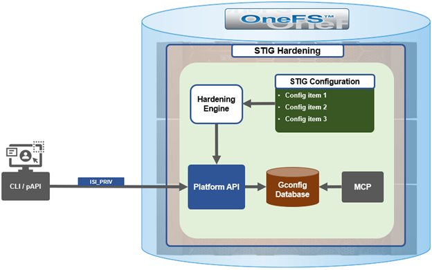
In the first article in this series, we took a look at the architecture and enhancements to security hardening in OneFS 9.5. Now we turn out attention to its preparation, configuration, and activation.
Applying a hardening profile is just one of multiple steps required in order to configure a STIG-compliant PowerScale cluster.
OneFS 9.5 security hardening comes pre-installed on a cluster, but not activated by default. Hardening is a licensed feature, and there are no changes to the licensing requirements or structure for OneFS 9.5 and later.
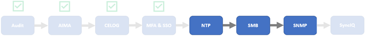
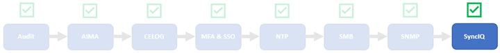
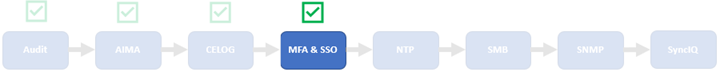
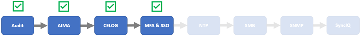
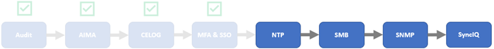
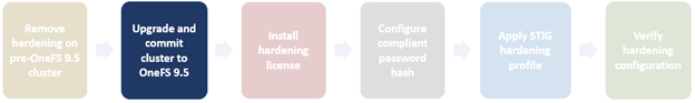
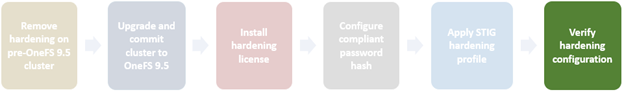
Applying a hardening profile is one of multiple steps required in order to configure a STIG-compliant PowerScale cluster. As such, the general process to apply and activate security hardening on a OneFS 9.5 or later cluster is as follows:
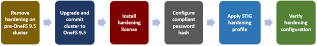
The specifics for each step are covered below:
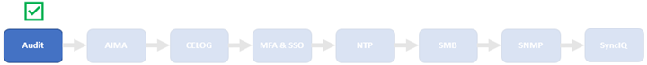
- Revert hardening on a cluster running OneFS 9.4 or earlier prior to upgrade.
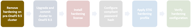
Upgrading from a STIG-hardened OneFS 9.4 or earlier cluster to OneFS 9.5 and later is not supported:
| Cluster Type |
Upgrade Details |
| Non-hardened cluster |
Upgrade to OneFS 9.5 on non-STIG hardened clusters is straightforward. |
| Hardened cluster |
Upgrade from a STIG-hardened pre-OneFS 9.5 cluster to OneFS 9.5 is not supported. Revert cluster to a non-hardened state prior to upgrade to OneFS 9.5. |
As such, if the cluster currently has hardening enabled, this must be reverted before upgrading to OneFS 9.5 or later.
To accomplish this, first, log in to the cluster’s CLI with a user account with the ‘ISI_PRIV_HARDENING’ RBAC role.
OneFS security hardening requires a license in order to be activated. If it is licensed, hardening can be applied as follows:
# isi hardening apply STIG
Apply Started
This may take several minutes
……
Applied Hardening profile successfully.
#
Once applied, hardening can be verified as follows:
# isi hardening status
Cluster Name: TME1
Hardening Status: Hardened
Profile: STIG
Following is the nodewise status:
TME1-1 : Enabled
TME1-2 : Enabled
TME1-3 : Enabled
TME1-4 : Enabled
Hardening can be easily removed on clusters running OneFS 9.4 or earlier:
# isi hardening revert
Revert Started
This may take several minutes
……
Reverting Hardening profile successful
#
# isi hardening status
Cluster Name: TME1
Hardening Status: Not Hardened
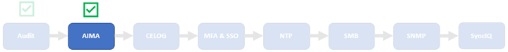
- Upgrade cluster to OneFS 9.5 or later.
The cluster must be running OneFS 9.5 or later in order to activate STIG hardening. If upgrading from an earlier release, the OneFS 9.5 or later upgrade must be committed before enabling hardening.
Upgrading a cluster on which security hardening has not been activated to OneFS 9.5 or later is straightforward and can be accomplished either by a simultaneous or rolling reboot strategy.
For example, to start a rolling upgrade, which is the default, run:
# isi upgrade cluster start <upgrade_image>
Similarly, the following CLI syntax will initiate a simultaneous upgrade:
# isi upgrade cluster start --simultaneous <upgrade_image>
Since OneFS supports the ability to roll back to the previous version, in-order to complete an upgrade it must be committed.
# isi upgrade cluster commit
The isi upgrade view CLI command can be used to monitor how the upgrade is progressing:
# isi upgrade view
Or, for an interactive session:
# isi upgrade view --interactive
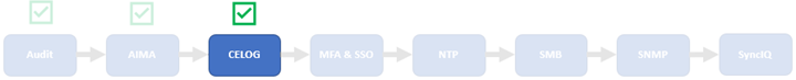
- Install hardening license.
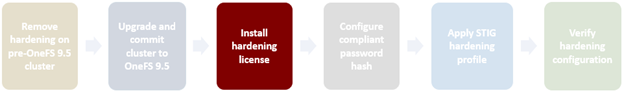
To enable STIG hardening on versions prior to OneFS 9.5, first check that hardening is licensed on the cluster:
# isi license list | grep -i harden
HARDEN 4 Nodes 4 Nodes Evaluation
A hardening license can be added as follows:
# isi license add <path_to_licenese_file>
Alternatively, a 90-day trial license can be activated on a lab/test cluster to evaluate STIG hardening:
# isi license add --evaluation HARDENING
If a current OneFS hardening license is not available when attempting to activate security hardening on a cluster, the following warning will be returned:
# isi hardening apply STIG
The HARDENING application is not currently installed. Please contact your Isilon account team for more information on evaluating and purchasing HARDENING.
- Configure compliant password hash.
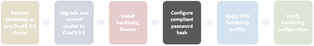
Before activating security hardening with the STIG profile, the password hash type should be set to use SHA512. For example:
# isi auth file modify System --password-hash-type=SHA512
NTLM support and authentication for all file protocols has been disabled for this provider due to change of password hash type.
# isi auth local modify System --password-hash-type=SHA512
Next, the account of last resort (ALR), which is ‘root’ on a PowerScale cluster, should be set to use this updated password hash type.
# isi auth users change-password root
If this step is skipped, attempts to apply hardening will fail with the following warning:
The hardening request was not accepted:
Account of last resort does not have a password set with a supported hash type (SHA256, SHA512): root.
The hardening profile was not applied.
Please see the Security Configuration Guide for guidance on how to set compatible account passwords.
The SSH key exchange algorithms should also be updated at this time with the following CLI syntax:
# isi ssh settings modify --kex-algorithms 'diffie-hellman-group16-sha512,diffie-hellman-group18-sha512,ecdh-sha2-nistp384'
Finally, update the SSH ciphers as follows:
# isi ssh settings modify --ciphers 'aes256-ctr,aes256-gcm@openssh.com'
- Activate STIG hardening.
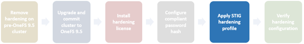
The next step involves actually applying the STIG hardening profile. This can be accomplished as follows:
# isi hardening apply STIG
..............Hardening operation complete.
Note that password restrictions are only enforced for password changes that occur after applying hardening.
After applying the STIG hardening profile, it is possible to re-apply the default (non-hardened) configuration with the following CLI syntax, which will undo the changes that hardening invoked. For example:
# isi hardening disable STIG

.........Hardening operation complete.
Note that with OneFS 9.5 and earlier, the ‘disable’ attempts to undo the effects of hardening, but does not guarantee a full restore of a prior cluster configuration. This differs from the OneFS 9.4 and earlier hardening ‘isi hardening revert’ CLI command and process described in ‘step 1’ above.
- Verify hardening configuration.
Finally, verify that the STIG hardening configuration was successful. This will be indicated by a status of ‘Applied’. For example:
# isi hardening list
Name  Description                       Status
-----------------------------------------------
STIG  Enable all STIG security settings Applied
-----------------------------------------------
Total: 1
Additionally, a report can be generated that provides a detailed listing of all the individual rules and their per-node status. For example:
# isi hardening report view STIG
logout_zsh_clear_screen Node 1 Applied /etc/zlogout
logout_profile_clear_screen Node 1 Applied /etc/profile
logout_csh_clear_screen Node 1 Applied /etc/csh.logout
require_password_single_user_mode Node 1 Applied /etc/ttys
set_password_min_length_pam_01 Node 1 Applied /etc/pam.d/system
set_password_min_length_pam_02 Node 1 Applied /etc/pam.d/other
set_password_min_length_pam_03 Node 1 Applied /etc/pam.d/passwd
set_password_min_length_pam_04 Node 1 Applied /etc/pam.d/passwd
disable_apache_proxy Node 1 Applied /etc/mcp/templates/isi_data_httpd.conf
disable_apache_proxy Node 1 Applied /etc/mcp/templates/isi_data_httpd.conf
disable_apache_proxy Node 1 Applied /etc/mcp/templates/isi_data_httpd.conf
set_shell_timeout_01 Node 1 Applied /etc/profile
set_shell_timeout_02 Node 1 Applied /etc/zshrc
set_shell_timeout_03 Node 1 Applied /etc/zshrc
set_shell_timeout_04 Node 1 Applied /etc/csh.cshrc
set_dod_banner_02 Node 1 Applied symlink:/etc/issue
check_node_default_umask Node 1 Applied umask
set_celog_snmp_use_fips Cluster Applied N/A
disable_supportassist Cluster Applied -
disable_usb_ports Cluster Applied /security/settings:usb_ports_disabled
disable_ndmpd Cluster Applied /protocols/ndmp/settings/global:service
enable_smtp_ssl Cluster Applied /1/cluster/email:smtp_auth_security
enable_onefs_cli Cluster Applied /security/settings:restricted_shell_enabled
set_min_password_percent_of_characters_changed Cluster Applied /16/auth/providers/local:password_percent_changed
set_ads_ldap_sign_and_seal Cluster Applied -
set_ads_ldap_sign_and_seal_default Cluster Applied registry.Services.lsass.Parameters.Providers.ActiveDirectory.LdapSignAndSeal
set_ads_machine_password_changes Cluster Applied -
limit_ads_machine_password_lifespan Cluster Applied -
enable_firewall Cluster Applied /network/firewall/settings:enabled
disable_audit_log_delete Cluster Applied /ifs/.ifsvar/audit/log_delete
set_audit_retention_period Cluster Applied /audit/settings/global:retention_period
disable_webui_access_ran Cluster Applied webui_ran_access
set_ssh_config_client_alive_interval Cluster Applied client_alive_interval
set_ssh_config_client_alive_count Cluster Applied client_alive_count_max
set_nfs_security_flavors Cluster Applied /protocols/nfs/exports:security_flavors
set_nfs_security_flavors Cluster Applied /protocols/nfs/exports:security_flavors
set_nfs_security_flavors Cluster Applied /protocols/nfs/exports:security_flavors
set_nfs_security_flavors Cluster Applied /protocols/nfs/exports:security_flavors
set_nfs_security_flavors Cluster Applied /protocols/nfs/exports:security_flavors
set_nfs_default_security_flavors Cluster Applied /protocols/nfs/settings/export:security_flavors
set_nfs_default_security_flavors Cluster Applied /protocols/nfs/settings/export:security_flavors
set_nfs_default_security_flavors Cluster Applied /protocols/nfs/settings/export:security_flavors
set_nfs_default_security_flavors Cluster Applied /protocols/nfs/settings/export:security_flavors
set_nfs_default_security_flavors Cluster Applied /protocols/nfs/settings/export:security_flavors
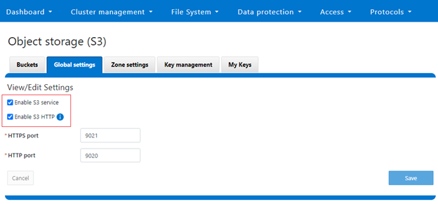
set_s3_https_only Cluster Applied /protocols/s3/settings/global:https_only
check_ipmi_enabled Cluster Applied -
set_cnsa_crypto_http Cluster Applied cipher_suites
set_cnsa_crypto_webui Cluster Applied cipher_suites
disable_hdfs Cluster Applied registry.Services.lsass.Parameters.Zones.System.HdfsEnabled
disable_webhdfs Cluster Applied registry.Services.lsass.Parameters.Zones.System.WebHdfsEnabled
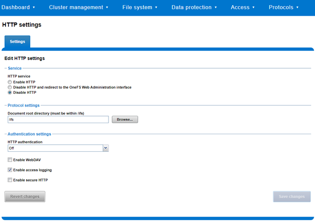
disable_http_basic_authentication Cluster Applied /protocols/http/settings:basic_authentication
disable_http_dav Cluster Applied /protocols/http/settings:dav
enable_http_integrated_authentication Cluster Applied /protocols/http/settings:integrated_authentication
set_apache_loglevel Cluster Applied log_level
set_apache_inactive_timeout Cluster Applied /protocols/http/settings:inactive_timeout
set_apache_session_max_age Cluster Applied /protocols/http/settings:session_max_age
disable_cee Cluster Applied /audit/settings/global:cee_server_uris
check_stig_celog_alerts Cluster Not Applied Military Unique Deployment Guide manually configured CELOG settings.
set_auth_concurrent_session_limit Cluster Applied 16/auth/settings/global:concurrent_session_limit
set_ldap_tls_revocation_check_level Cluster Applied -
set_ldap_default_tls_revocation_check_level Cluster Applied /auth/settings/global:default_ldap_tls_revocation_check_level
set_synciq_require_encryption Cluster Applied 14/sync/settings:encryption_required
check_synciq_default_ocsp_settings Cluster Not Applied /sync/settings/:cluster_certificate_id
check_synciq_policy_ocsp_settings Cluster Not Applied /sync/policies/:ocsp_issuer_certificate_id
check_daemon_user_disabled Cluster Applied /auth/users/USER:daemon/:enabled
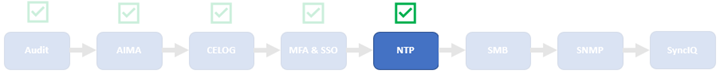
check_multiple_ntp_servers_configured Cluster Not Applied /protocols/ntp/servers:total
check_celog_smtp_channels_use_tls Cluster Applied -
set_apache_service_timeout Cluster Applied /protocols/http/settings:service_timeout
set_dm_tls_revocation_check_level Cluster Applied /datamover/certificates/settings/:revocation_setting
check_one_account_of_last_resort Cluster Applied Number of UID:0 accounts configured
set_krb5_default_tgs_enctypes Cluster Applied /auth/settings/krb5/defaults:default_tgs_enctypes
set_krb5_default_tkt_enctypes Cluster Applied /auth/settings/krb5/defaults:default_tkt_enctypes
set_krb5_permitted_enctypes Cluster Applied /auth/settings/krb5/defaults:permitted_enctypes
set_krb5_preferred_enctypes Cluster Applied /auth/settings/krb5/defaults:preferred_enctypes
set_local_lockouts_duration Cluster Applied /auth/providers/local/:lockout_duration
set_local_lockouts_threshold Cluster Applied /auth/providers/local/:lockout_threshold
set_local_lockouts_window Cluster Applied /auth/providers/local/:lockout_window
set_local_max_password_age Cluster Applied /auth/providers/local/:max_password_age
set_local_min_password_age Cluster Applied /auth/providers/local/:min_password_age
set_local_password_chars_changed Cluster Applied /auth/providers/local/:min_password_length
set_local_max_inactivity Cluster Applied /auth/providers/local/:max_inactivity_days
set_global_failed_login_delay Cluster Applied /auth/settings/global:failed_login_delay_time
set_ldap_require_secure_connection Cluster Applied -
set_ldap_do_not_ignore_tls_errors Cluster Applied -
set_ldap_tls_protocol_min_version Cluster Applied -
set_ldap_ntlm_support Cluster Applied -
disable_nis Cluster Applied -
disable_duo Cluster Applied /auth/providers/duo/:enabled
set_ntlm_support_file Cluster Applied /auth/providers/file/:ntlm_support
check_password_hashes Cluster Applied lsa-file-provider:System:root password hash
set_file_enabled Cluster Applied /auth/users/<USER>:enabled
set_local_disabled_when_inactive Cluster Applied /auth/users/<USER>:disabled_when_inactive
set_local_disabled_when_inactive_default Cluster Applied registry.Services.lsass.Parameters.Providers.Local.DefaultDisableWhenInactive
set_auth_webui_sso_mfa_enabled Cluster Applied auth/providers/saml-services/settings?zone=System:sso_enabled
set_auth_webui_sso_mfa_idp Cluster Not Applied auth/providers/saml-services/idps/System
set_auth_webui_sso_mfa_sp_host Cluster Not Applied auth/providers/saml-services/sp?zone=System:hostname
set_auth_webui_sso_mfa_required Cluster Applied authentication_mode
disable_remotesupport Cluster Applied /auth/users/USER:remotesupport/:enabled
enable_audit_1 Cluster Applied /audit/settings/global:protocol_auditing_enabled
enable_audit_2 Cluster Applied /audit/settings:syslog_forwarding_enabled
disable_vsftpd Cluster Applied /protocols/ftp/settings:service
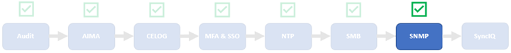
disable_snmpv1_v2 Cluster Applied 5/protocols/snmp/settings:snmp_v1_v2c_access
set_snmp_v3_auth_protocol_sha Cluster Applied 5/protocols/snmp/settings:snmp_v3_auth_protocol
disable_srs Cluster Applied /esrs/status:enabled
set_password_min_length Cluster Applied /auth/providers/local/:min_password_length
set_min_password_complexity Cluster Applied /auth/providers/local/:password_complexity
set_password_require_history Cluster Applied /auth/providers/local/:password_history_length
disable_coredump_minidump Cluster Applied /etc/mcp/templates/sysctl.conf
set_dod_banner_01 Cluster Applied /cluster/identity:motd_header
set_listen_on_ip_controlpath Cluster Applied listen_on_ip
set_listen_on_ip_datapath Cluster Applied listen_on_ip
enable_fips_mode Cluster Applied /security/settings:fips_mode_enabled
disable_kdb Cluster Applied /etc/mcp/templates/sysctl.conf
disable_basic_auth Cluster Applied auth_basic
disable_cava Cluster Applied /avscan/settings:service_enabled
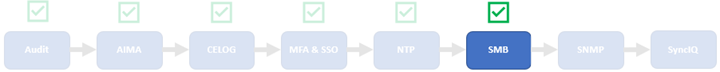
require_smb3_encryption Cluster Applied /protocols/smb/settings/global:support_smb1