OneFS Networking and Client Connection Balancing

In the previous articles in this series, we’ve looked at the fundamentals of a cluster’s network infrastructure:

The complete cluster architecture – software, hardware, and network – all cooperate to provide a distributed single file system that can scale dynamically as workloads and capacity and/or throughput needs change in a scale-out environment.

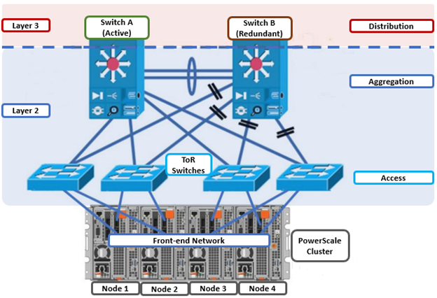
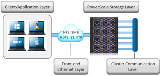
OneFS SmartConnect provides the load balancing services that work at the front-end Ethernet layer to evenly distribute client connections across the cluster. SmartConnect supports dynamic NFS failover and failback for Linux and UNIX clients and SMB3 continuous availability for Windows clients. This ensures that when a node failure occurs, or preventative maintenance is performed, all in-flight reads and writes are handed off to another node in the cluster to finish its operation without any user or application interruption.

During failover, clients are evenly redistributed across all remaining nodes in the cluster, ensuring minimal performance impact. If a node is brought down for any reason, including a failure, the virtual IP addresses on that node is seamlessly migrated to another node in the cluster.

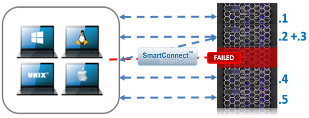
When the offline node is brought back online, SmartConnect automatically rebalances the NFS and SMB3 clients across the entire cluster to ensure maximum storage and performance utilization. For periodic system maintenance and software updates, this functionality allows for per-node rolling upgrades affording full-availability throughout the duration of the maintenance window.

The OneFS SmartConnect module itself can be run in two modes – with or without a license:

SmartConnect Attribute SmartConnect Basic (unlicensed) SmartConnect Advanced (Licensed)
Connection Balancing Round-robin only. Round-robin, CPU utilization, connection counting, and throughput balancing.
Address Allocation Static IP allocation only. Static and dynamic IP address allocation, up to a maximum of six SmartConnect Service IP addresses per subnet.
Address Failover No IP address failover policy. Supports defining a failover policy for the IP address pool.
Address Rebalance No IP address rebalance policy. Supports defining a rebalance policy for the IP address pool.
Per-pool Addresses Up to two IP address pools per external network subnet Supports multiple IP address pools per external subnet to enable multiple DNS zones within a single subnet.

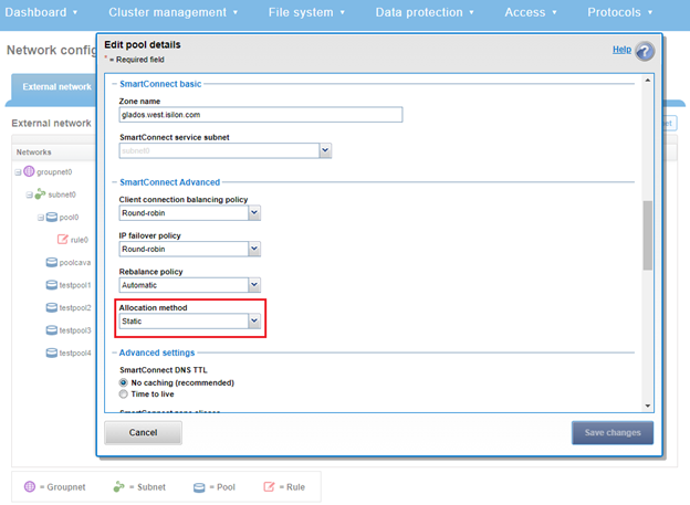
The SmartPools static vs dynamic address allocation method indicates whether the IP addresses in the pool can move back and forth between nodes when a node goes down. As such, a static IP pool displays the following characteristics:

  • Each interface in the pool gets exactly one IP (assuming there are at least as many IPs as interfaces in the pool).
  • If there are more IPs in the pool than interfaces, the additional IPs will not be allocated to any interface.
  • IPs do not move from one interface to another.
  • If an interface goes down, then the IP also goes down.

Conversely, in a dynamic IP pool:

  • Each of the IPs in the pool is allocated to an interface in the pool.
  • When an interface goes down in the pool, the IPs on that interface automatically move to another interface in the pool (preferring interfaces in the pool that are on the same node as the downed interface).
  • When a node is transitions to an ‘unhealthy’ state, the IPs on that node automatically move to another node in the pool.
  • When a node transitions back to a ‘healthy’ state, IPs will automatically move back to that node, assuming the rebalance policy is set to ‘auto’ and there are enough IPs available.

By default, OneFS SmartConnect balances connections among nodes using a round-robin policy and a separate IP pool for each subnet. A SmartConnect license adds advanced balancing policies to evenly distribute CPU usage, client connections, or throughput. It also lets you define IP address pools to support multiple DNS zones in a subnet.

Load-balancing Policy General Few Clients with High Usage Many Persistent NFS & SMB Connections Many Ephemeral Connections (HTTP, FTP) NFS Automount of UNC Paths are Used
Round Robin (Default)
Connection Count
CPU Usage
Network Throughput

Connection policies other than round robin are sampled every 10 seconds. The CPU policy is sampled every 5 seconds. If multiple requests are received during the same sampling interval, SmartConnect will attempt to balance these connections by estimating or measuring the additional load.

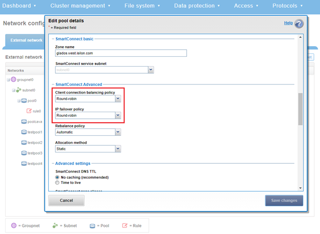
A ‘round robin’ load balancing strategy is generally a safe bet for both client connection balancing and IP failover.

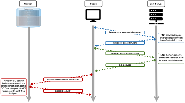
Under the hood, SmartConnect acts as DNS delegation server, responding to requests and returning IP addresses for the appropriate SmartConnect zone(s). The general transactional flow is as follows:

During a cluster ‘split’ or ‘merge’ group change the SmartConnect service will not respond to DNS inquiries. This is seldom as group changes typically take around 30 seconds. However, the time taken for a group change to complete can vary due to the load on the cluster at the time of the change. Any time a node is added, removed, or rebooted in a cluster there will be two group changes that cause SmartConnect to be impacted, one from down/split and one from up/merge.

For large clusters, if group changes are adversely impacting SmartConnect’s load-balancing performance, the core site DNS servers can be configured to use a Round Robin configuration instead of redirecting DNS requests to SmartConnect

SmartConnect supports IP failover to provide continuous access to data when hardware or a network path fails. Dynamic failover is recommended for high availability workloads on SmartConnect subnets that handle traffic from NFS clients.

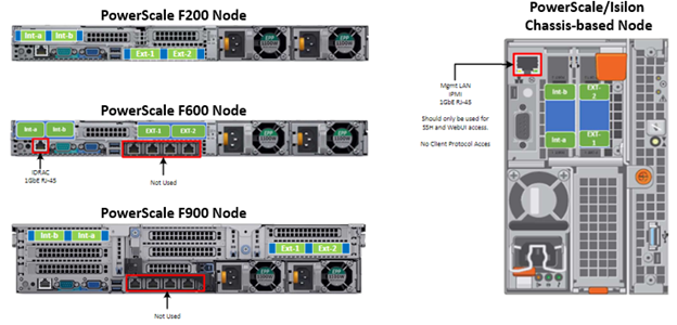
For optimal network performance, avoid mixing interface types (100/40/25/10 GbE) in the same SmartConnect Pool and/or mixing node types with different performance profiles, such as H700 and A300 interfaces, for example. In general, the ‘round-robin’ SmartConnect Client Connection Balancing and IP-failover policies provide the most consistent results.

To evenly distribute connections and optimize performance, the recommendation is to size SmartConnect for the expected number of connections and for the anticipated overall throughput likely to be generated. The sizing factors for a pool include the total number of concurrently active client connections, the anticipated aggregate throughput for the pool, and he minimum performance and throughput requirements in case an interface fails.

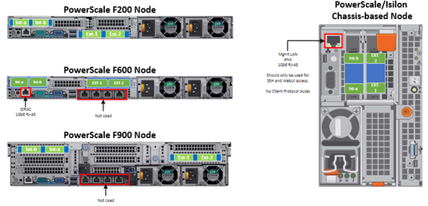
Since OneFS is a single volume, fully distributed file system, a client can access all the files and associated metadata that are stored on the cluster, regardless of the type of node a client connects to or the node pool on which the data resides. For example, data stored for performance reasons on a pool of F-Series all-flash nodes can be mounted and accessed by connecting to an A-Series node in the same cluster. The different types of PowerScale nodes, however, deliver different levels of performance.

To avoid unnecessary network latency under most circumstances, the recommendation is to configure SmartConnect subnets such that client connections are to the same physical pool of nodes on which the data resides. In other words, if a workload’s data lives on a pool of F600 nodes for performance reasons, the clients that work with that data should mount the cluster through a pool that includes the same F600 nodes that host the data.

Keep in mind the following networking and name server considerations:

  • Minimize disruption by suspending nodes in preparation for planned maintenance and resuming them after maintenance is complete
  • Leverage the groupnet feature to enhance multi-tenancy and DNS delegation, where desirable.
  • Ensure traffic flows through the right interface by tracing routes. Leverage OneFS Source-Based Routing (SBR) feature to keep traffic on desired paths.

If firewalling or filtering is deployed within the network, ensure that the appropriate ports are open. For example, open both UDP port 53 and TCP port 53 for the DNS service.

The client never sends a DNS request directly to the cluster. Instead, the site nameservers handle DNS requests from clients and route the requests appropriately.

In order to successfully distribute IP addresses, the OneFS SmartConnect DNS delegation server answers DNS queries with a time-to-live (TTL) of 0 so that the answer is not cached. Certain DNS servers (particularly Windows DNS Servers) will fix the value to one second. If you have many clients requesting an address within the same second, this will cause all of them to receive the same address. If you encounter this problem, you may need to use a different DNS server, such as BIND.

Certain clients perform DNS caching and might not connect to the node with the lowest load if they make multiple connections within the lifetime of the cached address. Recommend turning off client DNS caching, where possible. To handle client requests properly, SmartConnect requires that clients use the latest DNS entries.

The site DNS servers must be able to communicate with the node that is currently hosting the SmartConnect service. This is the node with the lowest logical node number (LNN) with an active interface in the subnet that contains the SSIP address.

OneFS Hardware Network Considerations

As we’ve seen in prior articles in this series, OneFS and the PowerScale platforms support a variety of Ethernet speeds, cable and connector styles, and network interface counts, depending on the node type selected. However, unlike the back-end network, Dell does not specify particular front-end switch models, allowing PowerScale clusters to seamlessly integrate into the data link layer (layer 2) of an organization’s existing Ethernet IP network infrastructure. For example:

A layer 2 looped topology as above extends VLANs between the distribution/aggregation switches, with spanning tree protocol (STP) preventing network loops by shutting down redundant paths. The access layer uplinks may be used to load balance VLANs. This distributed architecture allows the cluster’s external network to connect to multiple access switches, affording each node similar levels of availability, performance, and management properties.

Link aggregation can be used to combine multiple Ethernet interfaces into a single link-layer interface, and is implemented between a single switch and  PowerScale node, where transparent failover or switch port redundancy is required. Link aggregation assumes all links are full duplex, point to point, and at the same data rate, providing graceful recovery from link failures. If a link fails, traffic is automatically sent to the next available link without disruption.

Quality of service (QoS) can be implemented through differentiated services code point (DSCP), by specifying a value in the packet header that maps to an ‘effort level’ for traffic. Since OneFS does not provide an option for tagging packets with a specified DSCP marking, the recommended practice is to configure the first hop ports to insert DSCP values on the access switches connected to the PowerScale nodes. OneFS does retain headers for packets that already have a specified DSCP value, however.

When designing a cluster, the recommendation is that each node have at least one front-end interface configured, preferably in at least one static SmartConnect zone. Although a cluster can be run in a ‘not all nodes on the network’ (NANON) configuration, where feasible, the recommendation is to connect all nodes to the front-end network(s). Additionally, cluster services such as SNMP, ESRS, ICAP, and auth providers (AD, LDAP, NIS, etc) prefer each node to have an address that can reach the external servers.

In contrast with scale-up NAS platforms that use separate network interfaces for out-of-band management and configuration, OneFS traditionally performs all cluster network management in-band. However, PowerScale nodes typically contain a dedicated 1Gb Ethernet port that can be configured for use as a management network via ICMP or iDRAC, simplifying administration of a large cluster. OneFS also supports using a node’s serial port as an RS232 out-of-band management interface, and this practice is highly recommended for large clusters. Serial connectivity can provide reliable BIOS-level command line access for on-site or remote service staff to perform maintenance, troubleshooting and installation operations.

SmartConnect provides a configurable allocation method for each IP address pool:

Allocation Method Attributes
Static • One IP per interface is assigned, will likely require fewer IP’s to meet minimum requirements

• No Failover of IP’s to other interfaces

Dynamic • Multiple IP per interface is assigned, will require more IP’s to meet minimum requirements

• Failover of IP’s to other interfaces, Failback policies are needed

The default ‘static’ allocation assigns a single persistent IP address to each interface selected in the pool, leaving additional pool IP addresses  unassigned if the number of addresses exceeds the total interfaces.

The lowest IP address of the pool is assigned to the lowest Logical Node Number (LNN) from the selected interfaces, subsequently for the second-lowest IP address and LNN, etc. If a node or interface becomes unavailable, this IP address does not move to another node or interface. Also, when the node or interface becomes unavailable, it is removed from the SmartConnect zone, and new connections will not be assigned to the node. Once the node is available again, SmartConnect will automatically add it back into the zone and assign new connections.

By contrast, ‘dynamic’ allocation divides all available IP addresses in the pool across all selected interfaces, and OneFS attempts to assign the IP addresses as evenly as possible. However, if the interface-to-IP address ratio is not an integer value, a single interface might have more IP addresses than another. As such, wherever possible, ensure that all the interfaces have the same number of IP addresses.

In concert with dynamic allocation, dynamic failover provides high availability by transparently migrating IP addresses to another node when an interface is not available. If a node becomes unavailable, all the IP addresses it was hosting are reallocated across the new set of available nodes in accordance with the configured failover load-balancing policy. The default IP address failover policy is round robin, which evenly distributes IP addresses from the unavailable node across available nodes. Because the IP address remains consistent, irrespective of which node it resides on, failover to the client is transparent, so high availability is seamless.

The other available IP address failover policies are the same as the initial client connection balancing policies, that is, connection count, throughput, or CPU usage. In most scenarios, round robin is not only the best option but also the most common. However, the other failover policies are available for specific workflows.

The decision on whether to implement dynamic failover is highly dependent on the protocol(s) being used, general workflow attributes, and any high-availability design requirements:

Protocol State Suggested Allocation Strategy
NFSv3 Stateless Dynamic
NFSv4 Stateful Dynamic or Static, depending on mount daemon, OneFS version, and Kerberos.
SMB Stateful Dynamic or Static
SMB Multi-channel Stateful Dynamic or Static
S3 Stateless Dynamic or Static
HDFS Stateful Dynamic or Static. HDFS uses separate name-node and data-node connections. Allocation strategy depends on need for data locality and/or multi-protocol. Ie:

HDFS + NFSv3 : Dynamic Pool

HDFS + SMB : Static Pool

HTTP Stateless Static
FTP Stateful Static
SyncIQ Stateful Static required

Assigning each workload or data store to a unique IP address enables OneFS SmartConnect to move each workload to one of the other interfaces, minimizing the additional work that a remaining node in the SmartConnect pool must absorb and ensuring that the workload is evenly distributed across all the other nodes in the pool.

Static IP pools require one IP address for each logical interface within the pool. Since each node provides two interfaces for external networking, if link aggregation is not configured, this would require 2*N IP addresses for a static pool.

Determining the number of IP addresses within a dynamic allocation pool varies depending on the workflow, node count, and the estimated number of clients that would be in a failover event. While dynamic pools need, at a minimum, the number of IP addresses to match a pool’s node count, the ‘N * (N – 1)’ formula can often prove useful for calculating the required number of IP addresses for smaller pools. In this equation, N is the number of nodes that will participate in the pool

For example,  a SmartConnect pool with four-node interfaces, using the ‘N * (N – 1)’ model will result in three unique IP addresses being allocated to each node. A failure on one node interface will cause each of that interface’s three IP addresses to fail over to a different node in the pool. This ensures that each of the three active interfaces remaining in the pool receives one IP address from the failed node interface. If client connections to that node are evenly balanced across its three IP addresses, SmartConnect will evenly distribute the workloads to the remaining pool members. For larger clusters, this formula may not be feasible due to the sheer number of IP addresses required.

Enabling jumbo frames (Maximum Transmission Unit set to 9000 bytes) typically yields improved throughput performance with slightly reduced CPU usage than standard frames, where the MTU is set to 1500 bytes. For example, with 40 Gb Ethernet connections, jumbo frames provide about five percent better throughput and about one percent less CPU usage.

OneFS provides the ability to optimize storage performance by designating zones to support specific workloads or subsets of clients. Different network traffic types can be segregated on separate subnets using SmartConnect pools.

For large clusters, partitioning the cluster’s networking resources and allocating bandwidth to each workload can help minimize the likelihood that heavy traffic from one workload will affect network throughput for another. This is particularly true for SyncIQ replication and NDMP backup traffic, which can frequently benefit from its own set of interfaces, separate from user and client IO load.

The ‘groupnet’ networking object is part of OneFS’ support for multi-tenancy. Groupnets sit above subnets and pools and allow separate Access Zones to contain distinct DNS settings.

The management and data network(s) can then be incorporated into different Access Zones, each with their own DNS, directory access services, and routing, as appropriate.

OneFS Hardware Platform Considerations

A key decision for performance, particularly in a large cluster environment, is the type and quantity of nodes deployed. Heterogeneous clusters can be architected with a wide variety of node styles and capacities, in order to meet the needs of a varied data set and wide spectrum of workloads. These node styles encompass several hardware generations, and fall loosely into three main categories or tiers. While heterogeneous clusters can easily include many hardware classes and configurations, the best practice of simplicity for building clusters holds true here too.

Consider the physical cluster layout and environmental factors, particularly when designing and planning a large cluster installation. These factors include:

  • Redundant power supply
  • Airflow and cooling
  • Rackspace requirements
  • Floor tile weight constraints
  • Networking Requirements
  • Cabling distance Limitations

The following table details the physical dimensions, weight, power draw, and thermal properties for the range of PowerScale F-series all-flash nodes:

Model  

Tier

Height Width Depth RU Weight MaxWatts Watts Max BTU Normal BTU
F900 All-flash NVMe

performance

2U (2×1.75IN) 17.8 IN / 45 cm 31.8 IN / 85.9 cm 2RU  73 lbs 1297 859 4425 2931
F600 All-flash NVMe

Performance

1U

(1.75IN)

17.8 IN / 45 cm 31.8 IN / 85.9 cm 1RU  43 lbs 467 718 2450 1594
F200 All-flash Performance 1U

(1.75IN)

17.8 IN / 45 cm 31.8 IN / 85.9 cm 1RU  47 lbs 395 239 1346 816


Note that the table above represents individual nodes. A minimum of three of each node style are required for a node pool.

Similarly, the following table details the physical dimensions, weight, power draw, and thermal properties for the range of PowerScale chassis-based platforms:

Model  

Tier

Height Width Depth RU Weight MaxWatts Watts Max BTU Normal BTU
F800/810 All-flash

performance

4U (4×1.75IN) 17.6 IN / 45 cm 35 IN / 88.9 cm 4RU 169 lbs (77 kg) 1764 1300 6019 4436
H700  

Hybrid/Utility

4U (4×1.75IN) 17.6 IN / 45 cm 35 IN / 88.9 cm 4RU 261lbs (100 kg) 1920 1528 6551 5214
H7000  

Hybrid/Utility

4U (4×1.75IN) 17.6 IN / 45 cm 39 IN / 99.06 cm 4RU 312 lbs (129 kg) 2080 1688 7087 5760
H600  

Hybrid/Utility

4U (4×1.75IN) 17.6 IN / 45 cm 35 IN / 88.9 cm 4RU  213 lbs (97 kg) 1990 1704 6790 5816
H5600  

Hybrid/Utility

4U (4×1.75IN) 17.6 IN / 45 cm 39 IN / 99.06 cm 4RU 285 lbs (129 kg) 1906 1312 6504 4476
H500  

Hybrid/Utility

4U (4×1.75IN) 17.6 IN / 45 cm 35 IN / 88.9 cm 4RU 248 lbs (112 kg) 1906 1312 6504 4476
H400  

Hybrid/Utility

4U (4×1.75IN) 17.6 IN / 45 cm 35 IN / 88.9 cm 4RU 242 lbs (110 kg) 1558 1112 5316 3788
A300  

Archive

4U (4×1.75IN) 17.6 IN / 45 cm 35 IN / 88.9 cm 4RU 252 lbs (100 kg) 1460 1070 4982 3651
A3000  

Archive

4U (4×1.75IN) 17.6 IN / 45 cm 39 IN / 99.06 cm 4RU 303 lbs (129 kg) 1620 1230 5528 4197
A200  

Archive

4U (4×1.75IN) 17.6 IN / 45 cm 35 IN / 88.9 cm 4RU 219 lbs (100 kg) 1460 1052 4982 3584
A2000  

Archive

4U (4×1.75IN) 17.6 IN / 45 cm 39 IN / 99.06 cm 4RU 285 lbs (129 kg) 1520 1110 5186 3788


Note that the table above represents 4RU chassis, each of which contains four PowerScale platform nodes (the minimum node pool size).

Below are the locations of both the front end (ext-1 & ext-2) and back-end (int-1 & int-2) network interfaces on the PowerScale stand-alone F-series and chassis-based nodes:

A PowerScale cluster’s backend network is analogous to a distributed systems bus. Each node has two backend interfaces for redundancy that run in an active/passive configuration (int-1 and int-2 above). The primary interface is connected to the primary switch, and the secondary interface to a separate switch.

For nodes using 40/100 Gb or 25/10 Gb Ethernet or Infiniband connected with multimode fiber, the maximum cable length is 150 meters. This allows a cluster to span multiple rack rows, floors, and even buildings, if necessary. While this can solve floor space challenges, in order to perform any physical administration activity on nodes you must know where the equipment is located.

The table below shows the various PowerScale node types and their respective backend network support. While Ethernet is the preferred medium – particularly for large PowerScale clusters –Infiniband is also supported for compatibility with legacy Isilon clusters.

Node Models Details
F200, F600, F900 F200: nodes support a 10 GbE or 25 GbE connection to the access switch using the same NIC. A breakout cable can connect up to four nodes to a single switch port.

F600: nodes support a 40 GbE or 100 GbE connection to the access switch using the same NIC.

F900: nodes support a 40 GbE or 100 GbE connection to the access switch using the same NIC.

H700, H7000, A300, A3000 Supports 40 GbE or 100 GbE connection to the access switch using the same NIC.

OR

Supports 25 GbE or 10 GbE connection to the leaf using the same NIC. A breakout cable can connect a 40 GbE switch port to four 10 GbE nodes or a 100 GbE switch port to four 25 GbE nodes.

F810, F800, H600, H500, H5600 Performance nodes support a 40 GbE connection to the access switch.
A200, A2000, H400 Archive nodes support a 10GbE connection to the access switch using a breakout cable. A breakout cable can connect a 40 GbE switch port to four 10 GbE nodes or a 100 GbE switch port to four 10 GbE nodes.

Currently only Dell approved switches are supported for backend Ethernet and IB cluster interconnection. These include:

Switch

Model

Port Count Port Speed Height (Rack Units) Role Notes
Dell S4112 24 10GbE ½ ToR 10 GbE only.
Dell 4148 48 10GbE 1 ToR 10 GbE only.
Dell S5232 32 100GbE 1 Leaf or Spine Supports 4x10GbE or 4x25GbE breakout cables.

Total of 124 10GbE or 25GbE nodes as top-of-rack backend switch.

Port 32 does not support breakout.

Dell Z9100 32 100GbE 1 Leaf or Spine Supports 4x10GbE or 4x25GbE breakout cables.

Total of 128 10GbE or 25GbE nodes as top-of-rack backend switch.

Dell Z9264 64 100GbE 2 Leaf or Spine Supports 4x10GbE or 4x25GbE breakout cables.

Total of 128 10GbE or 25GbE nodes as top-of-rack backend switch.

Arista 7304 128 40GbE 8 Enterprise core 40GbE or 10GbE line cards.
Arista 7308 256 40GbE 13 Enterprise/ large cluster 40GbE or 10GbE line cards.
Mellanox Neptune MSX6790 36 QDR 1 IB fabric 32Gb/s quad data rate Infiniband.

Be aware that the use of patch panels is not supported for PowerScale cluster backend connections, regardless of overall cable lengths. All connections must be a single link, single cable directly between the node and backend switch. Also, Ethernet and Infiniband switches must not be reconfigured or used for any traffic beyond a single cluster.

Support for leaf spine backend Ethernet network topologies was first introduced in OneFS 8.2. In a leaf-spine network switch architecture, the PowerScale nodes connect to leaf switches at the access, or leaf, layer of the network. At the next level, the aggregation and core network layers are condensed into a single spine layer. Every leaf switch connects to every spine switch to ensure that all leaf switches are no more than one hop away from one another. For example:

Leaf-to-spine switch connections require even distribution, to ensure the same number of spine connections from each leaf switch. This helps minimize latency and reduces the likelihood of bottlenecks in the back-end network. By design, a leaf spine network architecture is both highly scalable and redundant.

Leaf spine network deployments can have a minimum of two leaf switches and one spine switch. For small to medium clusters in a single rack, the back-end network typically uses two redundant top-of-rack (ToR) switches, rather than implementing a more complex leaf-spine topology.

OneFS Hardware Installation Considerations

When it comes to physically installing PowerScale nodes, most utilize a 35 inch depth chassis and will fit in a standard depth data center cabinet. Nodes can be secured to standard storage racks with their sliding rail kits, included in all node packaging and compatible with racks using either 3/8 inch square holes, 9/32 inch round holes, or 10-32 / 12-24 / M5X.8 / M6X1 pre-threaded holes. These supplied rail kit mounting brackets are adjustable in length from 24 inches to 36 inches to accommodate different rack depths. When selecting an enclosure for PowerScale nodes, ensure that the rack supports the minimum and maximum rail kit sizes.

Rack Component Description
a Distance between front surface of the rack and the front NEMA rail
b Distance between NEMA rails, minimum=24in (609.6mm), max=34in (863.6mm)
c Distance between the rear of the chassis to the rear of the rack, min=2.3in (58.42mm)
d Distance between inner front of the front door and the NEMA rail, min=2.5in (63.5mm)
e Distance between the inside of the rear post and the rear vertical edge of the chassis and rails, min=2.5in (63.5mm)
f Width of the rear rack post
g 19in (486.2mm)+(2e), min=24in (609.6mm)
h 19in (486.2mm) NEMA+(2e)+(2f)

Note: Width of the PDU+0.5in (13mm) <=e +f

If j=i+c+PDU depth+3in (76.2mm), then h=min 23.6in (600mm)

Assuming the PDU is mounted beyond i+c.

i Chassis depth: Normal chassis=35.80in (909mm) : Deep chassis=40.40in (1026mm)

Switch depth (measured from the front NEMA rail): Note: The inner rail is fixed at 36.25in (921mm)

Allow up to 6in (155mm) for cable bend radius when routing up to 32 cables to one side of the rack. Select the greater of the installed equipment.

j Minimum rack depth=i+c
k Front
l Rear
m Front door
n Rear door
p Rack post
q PDU
r NEMA
s NEMA 19 inch
t Rack top view
u Distance from front NEMA to chassis face:

Dell PowerScale deep and normal chassis = 0in

However, the high capacity models such as the F800/810, H7000, H5600, A3000 and A2000 have 40 inch depth chassis and require extended depth cabinets such as the APC 3350 or Dell Titan-HD rack.

Additional room must be provided for opening the FRU service trays at the rear of the nodes and, in the chassis-based 4RU platforms, the disk sleds at the front of the chassis. With the exception of the 2RU F900, the stand-alone PowerScale all-flash nodes are 1RU in height (including the 1RU diskless P100 accelerator and B100 backup accelerator nodes).

Power-wise, each cabinet typically requires between two and six independent single or three-phase power sources. To determine the specific requirements, use the published technical specifications and device rating labels for the devices to calculate the total current draw for each rack.

Specification North American 3 wire connection (2 L and 1 G) International 3 wire connection (1 L, 1 N, and 1 G)
Input nominal voltage 200–240 V ac +/- 10% L – L nom 220–240 V ac +/- 10% L – L nom
Frequency 50–60 Hz 50–60 Hz
Circuit breakers 30 A 32 A
Power zones Two Two
Power requirements at site (minimum to maximum) Single-phase: six 30A drops, two per zone

Three-phase Delta: two 50A drops, one per zone

Three-phase Wye: two 32A drops, one per zone

Single-phase: six 30A drops, two per zone

Three-phase Delta: two 50A drops, one per zone

Three-phase Wye: two 32A drops, one per zone

Additionally, the recommended environmental conditions to support optimal PowerScale cluster operation are as follows:

Attribute Details
Temperature Operate at >=90 percent of the time between 10 degrees celsiuses to 35 degrees celsius degrees celsius, and <=10 percent of the time between 5 degrees celsiuses to 40 degrees celsiuses.
Humidity 40 to 55 percent relative humidity
Weight A fully configured cabinet must sit on at least two floor tiles, and can weigh approximately 1588 kilograms (3500 pounds).
Altitude 0 meters to 2439 meters (0 to 8,000 ft) above sea level operating altitude.

Weight is a critical factor to keep in mind, particularly with the chassis-based nodes. Individual 4RU chassis can weigh up to around 300lbs each, and the maximum floor tile capacity for each individual cabinet or rack must be kept in mind.  For the deep node styles (H7000, H5600, A3000 and A2000), the considerable node weight may prevent racks from being fully populated with PowerScale equipment. If the cluster uses a variety of node types, installing the larger, heavier nodes at the bottom of each rack and the lighter chassis at the top can help distribute weight evenly across the cluster racks’ floor tiles.

Note that there are no lift handles on the PowerScale 4RU chassis. However, the drive sleds can be removed to provide handling points if no lift is available. With all the drive sleds removed, but leaving the rear compute modules inserted, the chassis weight drops to a more manageable 115lbs or so. It is strongly recommended to use a lift for installation of 4RU chassis.

Cluster backend switches ship with the appropriate rails (or tray) for proper installation of the switch in the rack. These rail kits are adjustable to fit NEMA front rail to rear rail spacing ranging from 22 in to 34 in.

Note that some manufacturers Ethernet switch rails are designed to overhang the rear NEMA rails, helping to align the switch with the PowerScale chassis at the rear of the rack. These require a minimum clearance of 36 in from the front NEMA rail to the rear of the rack, in order to ensure that the rack door can be closed.

Consider the following large cluster topology, for example:

This contiguous rack architecture is designed to scale up to the current maximum PowerScale cluster size of 252 nodes, in 63 4RU chassis, across nine racks as the environment grows – while still keeping cable management relatively simple. Note that this configuration assumes 1RU per node. If using F900 nodes, which are 2RU in size, additional rack capacity should be budgeted for.

Successful large cluster infrastructures depend heavily on the proficiency of the installer and their optimizations for maintenance and future expansion. Some good data center design practices include:

  • Pre-allocating and reserving adjacent racks in the same isle to fully accommodate the anticipated future cluster expansion
  • Reserving an empty ‘mailbox’ slot in the top half of each rack for any pass-through cable management needs.
  • Dedicating one of the racks in the group for the back-end and front-end distribution/spine switches – in this case rack R3.

For Hadoop workloads, PowerScale clusters are compatible with the rack awareness feature of HDFS to provide balancing in the placement of data. Rack locality keeps the data flow internal to the rack.

Excess cabling can be neatly stored in 12” service coils on a cable tray above the rack, if available, or at the side of the rack as illustrated below.

The use of intelligent power distribution units (PDUs) within each rack can facilitate the remote power cycling of nodes, if desired.

For deep nodes such as the H7000 and A3000 hardware, where chassis depth can be a limiting factor, horizontally mounted PDUs within the rack can be used in place of vertical PDUs, if necessary. If front-mounted, partial depth Ethernet switches are deployed, horizontal PDUs can be installed in the rear of the rack directly behind the switches to maximize available rack capacity.

With copper cables (SFP+, QSFP, CX4, etc) the maximum cable length is typically limited to 10 meters or less. After factoring in for dressing the cables to maintain some level of organization and proximity within the racks and cable trays, all the racks with PowerScale nodes need to be in close physical proximity to each other –either in the same rack row or close by in an adjacent row – or adopt a leaf-spine topology, with leaf switches in each rack.

If greater physical distance between nodes is required, support for multimode fiber (QSFP+, MPO, LC, etc) extends the cable length limitation to 150 meters. This allows nodes to be housed on separate floors or on the far side of a floor in a datacenter if necessary. While solving the floor space problem, this does have the potential to introduce new administrative and management challenges.

The various cable types, form factors, and supported lengths available for PowerScale nodes:

Cable Form Factor Medium Speed (Gb/s) Max Length
QSFP28 Optical 100Gb 30M
MPO Optical 100/40Gb 150M
QSFP28 Copper 100Gb 5M
QSFP+ Optical 40Gb 10M
LC Optical 25/10Gb 150M
QSFP+ Copper 40Gb 5M
SFP28 Copper 25Gb 5M
SFP+ Copper 10Gb 7M
CX4 Copper IB QDR/DDR 10M

The connector types for the cables above can be identified as follows:

As for the nodes themselves, the following rear views indicate the locations of the various network interfaces:

Note that Int-a and int-b indicate the primary and secondary back-end networks, whereas Ext-1 and Ext-2 are the front-end client networks interfaces.

Be aware that damage to the InfiniBand or Ethernet cables (copper or optical fibre) can negatively affect cluster performance. Never bend cables beyond the recommended bend radius, which is typically 10–12 times the diameter of the cable. For example, if a cable is 1.6 inches, round up to 2 inches and multiply by 10 for an acceptable bend radius.

Cables differ, so follow the explicit recommendations of the cable manufacturer.

The most important design attribute for bend radius consideration is the minimum mated cable clearance (Mmcc). Mmcc is the distance from the bulkhead of the chassis through the mated connectors/strain relief including the depth of the associated 90 degree bend. Multimode fiber has many modes of light (fiber optic) traveling through the core. As each of these modes moves closer to the edge of the core, light and the signal are more likely to be reduced, especially if the cable is bent. In a traditional multimode cable, as the bend radius is decreased, the amount of light that leaks out of the core increases, and the signal decreases. Best practices for data cabling include:

  • Keep cables away from sharp edges or metal corners.
  • Avoid bundling network cables with power cables. If network and power cables are not bundled separately, electromagnetic interference (EMI) can affect the data stream.
  • When bundling cables, do not pinch or constrict the cables.
  • Avoid using zip ties to bundle cables, instead use velcro hook-and-loop ties that do not have hard edges, and can be removed without cutting. Fastening cables with velcro ties also reduces the impact of gravity on the bend radius.

Note that the effects of gravity can also decrease the bend radius and result in degradation of signal power and quality.

Cables, particularly when bundled, can also obstruct the movement of conditioned air around the cluster, and cables should be secured away from fans, etc. Flooring seals and grommets can be useful to keep conditioned air from escaping through cable holes. Also ensure that smaller Ethernet switches are drawing cool air from the front of the rack, not from inside the cabinet. This can be achieved either with switch placement or by using rack shelving.

OneFS Hardware Environmental and Logistical Considerations

In this article, we turn our attention to some of the environmental and logistical aspects of cluster design, installation and management.

In addition to available rack space and physical proximity of nodes, provision needs to be made for adequate power and cooling as the cluster expands. New generations of drives and nodes typically deliver increased storage density, which often magnifies the power draw and cooling requirements per rack unit.

The recommendation is for a large cluster’s power supply to be fully redundant and backed up with a battery UPS and/or power generator. In the worst instance, if a cluster does loose power, the nodes are protected internally by filesystem journals which preserve any in-flight uncommitted writes. However, the time to restore power and bring up a large cluster from an unclean shutdown can be considerable.

Like most data center equipment, the cooling fans in PowerScale nodes and switches pull air from the front to back of the chassis. To complement this, data centers often employ a hot isle/cold isle rack configuration, where cool, low humidity air is supplied in the aisle at the front of each rack or cabinet either at the floor or ceiling level, and warm exhaust air is returned at ceiling level in the aisle to the rear of each rack.

Given the significant power draw, heat density, and weight of cluster hardware, some datacenters are limited in the number of nodes each rack can support. For partially filled racks, the use of blank panels to cover the front and rear of any unfilled rack units can help to efficiently direct airflow through the equipment.

The table below shows the various front and back-end network speeds and connector form factors across the PowerScale storage node portfolio.

Speed (Gb/s) Form Factor Front-end/

Back-end

Supported Nodes
100/40 QSFP28 Back-end F900, F600, H700, H7000, A300, A3000, P100, B100
40

QDR

QSFP+ Back-end F800, F810, H600, H5600, H500, H400, A200, A2000
25/10 SFP28 Back-end F900, F600, F200, H700, H7000, A300, A3000, P100, B100
10

QDR

QSFP+ Back-end H400, A200, A2000
100/40 QSFP28 Front-end F900, F600, H700, H7000, A300, A3000, P100, B100
40

QDR

QSFP+ Front-end F800, F810, H600, H5600, H500, H400, A200, A2000
25/10 SFP28 Front-end F900, F600, F200, H700, H7000, A300, A3000, P100, B100
25/10 SFP+ Front-end F800, F810, H600, H5600, H500, H400, A200, A2000
10

QDR

SFP+ Front-end F800, F810, H600, H5600, H500, H400, A200, A2000

With large clusters, especially when the nodes may not be racked in a contiguous manner, having all the nodes and switches connected to serial console concentrators and remote power controllers is highly advised. However, to perform any physical administration or break/fix activity on nodes you must know where the equipment is located and have administrative resources available to access and service all locations.

As such, the following best practices are recommended:

  • Develop and update thorough physical architectural documentation.
  • Implement an intuitive cable coloring standard.
  • Be fastidious and consistent about cable labeling.
  • Use the appropriate length of cable for the run and create a neat 12” loop of any excess cable, secured with Velcro.
  • Observe appropriate cable bend ratios, particularly with fiber cables.
  • Dress cables and maintain a disciplined cable management ethos.
  • Keep a detailed cluster hardware maintenance log.
  • Where appropriate, maintain a ‘mailbox’ space for cable management.

Disciplined cable management and labeling for ease of identification is particularly important in larger PowerScale clusters, where density of cabling is high. Each chassis can require up to twenty eight cables, as shown in the table below:

Cabling Component Medium Cable Quantity per Chassis


Back end network Ethernet or Infiniband 8
Front end network Ethernet 8
Management Interface 1Gb Ethernet 4
Serial Console DB9 RS 232 4
Power cord 110V or 220V AC power 4
Total 28

The recommendation for cabling a PowerScale chassis is as follows:

  • Split cabling in the middle of the chassis, between nodes 2 and 3.
  • Route Ethernet and Infiniband cables towards lower side of the chassis.
  • Connect power cords for nodes 1 and 3 to PDU A and power cords for nodes 2 and 4 to PDU B.
  • Bundle network cables with the AC power cords for ease of management.
  • Leave enough cable slack for servicing each individual node’s FRUs.

Similarly, the stand-alone F-series all flash nodes, in particular the 1RU F600 and F200 nodes, also have a similar density of cabling per rack unit:

Cabling Component Medium Cable Quantity per F-series node


Back end network 10 or 40 Gb Ethernet or QDR Infiniband 2
Front end network 10 or 40Gb Ethernet 2
Management Interface 1Gb Ethernet 1
Serial Console DB9 RS 232 1
Power cord 110V or 220V AC power 2
Total 8

Consistent and meticulous cable labeling and management is particularly important in large clusters. PowerScale chassis that employ both front and back end Ethernet networks can include up to twenty Ethernet connections per 4RU chassis.

In each node’s compute module, there are two PCI slots for the Ethernet cards (NICs). Viewed from the rear of the chassis, in each node the right hand slot (HBA Slot 0) houses the NIC for the front end network, and the left hand slot (HBA Slot 1) the NIC for the front end network. In addition to this, there is a separate built-in 1Gb Ethernet port on each node for cluster management traffic.

While there is no requirement that node 1 aligns with port 1 on each of the backend switches, it can certainly make cluster and switch management and troubleshooting considerably simpler. Even if exact port alignment is not possible, with large clusters, ensure that the cables are clearly labeled and connected to similar port regions on the backend switches.

PowerScale nodes and the drives they contain have identifying LED lights to indicate when a component has failed and to allow proactive identification of resources. The ‘isi led’ CLI command can be used to proactive illuminate specific node and drive indicator lights to aid in identification.

Drive repair times depend on a variety of factors:

  • OneFS release (determines Job Engine version and how efficiently it operates)
  • System hardware (determines drive types, amount of CPU and RAM, etc)
  • Filesystem: Amount of data, data composition (lots of small vs large files), protection, tunables, etc.
  • Load on the cluster during the drive failure

A useful method to estimate future FlexProtect runtime is to use old repair runtimes as a guide, if available.

The drives in the PowerScale chassis-based platforms have a bay-grid nomenclature, where A-E indicates each of the sleds and 0-6 would point to the drive position in the sled. The drive closest to the front is 0, whereas the drive closest to the back is 2/3/5, depending on the drive sled type.

When it comes to updating and refreshing hardware in a large cluster, swapping nodes can be a lengthy process of somewhat unpredictable duration. Data has to be evacuated from each old node during the Smartfail process prior to its removal, and restriped and balanced across the new hardware’s drives. During this time there will also be potentially impactful group changes as new nodes are added and the old ones removed.

However, if replacing an entire node-pool as part of a tech refresh, a SmartPools filepool policy can be crafted to migrate the data to another nodepool across the back-end network. When complete, the nodes can then be Smartfailed out, which should progress swiftly since they are now empty.

If multiple nodes are Smartfailed simultaneously, at the final stage of the process the node remove is serialized with around 60 seconds pause between each. The Smartfail job places the selected nodes in read-only mode while it copies the protection stripes to the cluster’s free space. Using SmartPools to evacuate data from a node or set of nodes in preparation to remove them is generally a good idea, and is usually a relatively fast process.

Another efficient approach can often be the swapping out of drives into new chassis. In addition to being considerable faster, the drive swapping process focuses the disruption on a single whole cluster down event. Estimating the time to complete a drive swap, or ‘disk tango’ process is simpler and more accurate and can typically be completed in a single maintenance window.

With PowerScale chassis-based platforms, such as the H700 and A300, the available hardware ‘tango’ options are expanded and simplified. Given the modular design of these platforms, the compute and chassis tango strategies typically replace the disk tango:

Replacement Strategy Component PowerScale

F-series

Chasis-based nodes Description
Disk tango Drives / drive sleds Swapping out data drives or drive sleds
Compute tango Chassis Compute modules Rather than swapping out the twenty drive sleds in a chassis, it’s usually cleaner to exchange the four compute modules
Chassis tango 4RU Chassis Typically only required if there’s an issue with the chassis mid-plane.

Note that any of the above ‘tango’ procedures should only be executed under the recommendation and supervision of Dell support.