OneFS CELOG Bulk Event Resolution

Another feature introduced in the OneFS 9.14 release is CELOG Bulk Event Resolution. But before we get into the details, first, a quick refresher. The OneFS Cluster Event Log (or CELOG) provides a single source for the logging of events that occur on a PowerScale cluster. Events are used to communicate a picture of cluster health for various components. CELOG provides a single point from which notifications about the events are generated, including sending alert emails and SNMP traps.

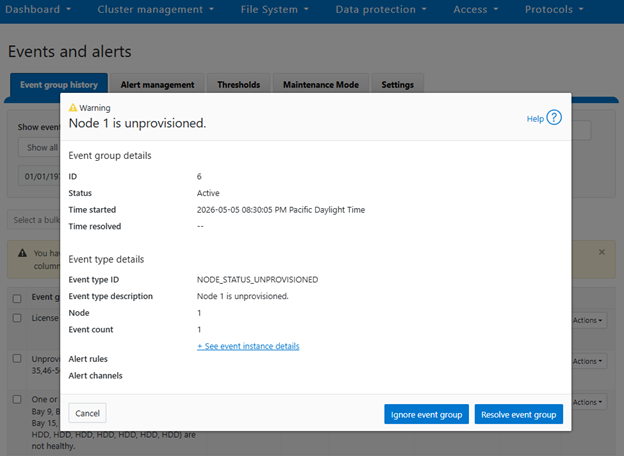
Cluster events can be easily viewed from the WebUI by browsing to Cluster Management > Events and Alerts > Events group history. For example:
Or from the CLI, using the ‘isi event events view’ syntax:

# isi event events view 2.370158

           ID: 2.370158

Eventgroup ID: 271428

   Event Type: 600010001

      Message: The snapshot daemon failed to create snapshot 'Hourly - prod' in schedule 'Hourly @ Every Day': error: Name collision

        Devid: 2

          Lnn: 2

         Time: 2026-05-08T17:01:33

     Severity: warning

        Value: 0.0

In the above instance, CELOG communicates on behalf of SnapshotIQ that it’s failed to create a scheduled hourly snapshot because of an issue with the naming convention.

At a high level, processes that monitor conditions on the cluster or log important events during the course of their operation communicate directly with the CELOG system. CELOG receives event messages from other processes via a well-defined API.

A CELOG event often contains the following elements:

Element Definition
Event Events are generated by the system and may be communicated in various ways (email, snmp traps, etc), depending upon the configuration.
Specifier Specifiers are strings containing extra information, which can be used to coalesce events and construct meaningful, readable messages.
Attachment Extra chunks of information, such as parts of log files or sysctl output, added to email notifications to provide additional context about an event.

For example, in SnapshotIQ event above, we can see the event text contains a specifier and attachment that has been mostly derived from the corresponding syslog message:

# grep "Hourly - prod" /var/log/messages* | grep "2026-05-08T17:01:33"

2026-05-08T17:01:33-04:00 <3.3> a200-2 isi_snapshot_d[5631]: create_schedule_snapshot: snapshot schedule (Hourly @ Every Day) pattern created a snapshot name collision (Hourly - prod); scheduled create failed.

CELOG is a large, complex system, which can be envisioned as a large pipeline. It gathers events and statistics info on one end from isi_stats_d and isi_celog_monitor, plus directly other applications such as SmartQuotas, SyncIQ, etc. These events are passed from one functional block to another, with a database at the end of the pipe. Along the way, attachments may be generated, notifications sent, and events passed to a coalescer.

On the front end, there are two dispatchers, which pass communication from the UNIX socket and network to their corresponding handlers. As events are processed, they pass through a series of coalescers. At any point they may be intercepted by the appropriate coalescer, which creates a coalescing event and which will accept other related events.

As events drop out the bottom of the coalescer stack, they’re deposited in add, modify and delete queues in the backend database infrastructure. The coalescer thread then moves onto pushing things into the local database, forwarding them along to the master coalescer, and queueing events to have notifications sent and/or attachments generated.

The processes of safely storing events, analyzing them, deciding on what alerts to send and sending them is separated into four separate modules within the pipeline:

The following table provides a description of each of these CELOG modules:

Component Definition
Capture The first stage in the processing pipeline, Event Capture is responsible for reading event occurrences from the kernel queue, storing them safely on persistent local storage, generating attachments, and queueing them by priority for analysis.
Analysis Extra chunks of information (log file extracts, sysctl output, etc) are added to alert notifications to provide additional context about an event.
Reporter The Reporter is the third stage in the processing pipeline, and runs on only one node in the cluster. It periodically queries Event Analysis for changes and generates alert requests for any relevant conditions.
Alerter The Alerter is the final stage in the processing pipeline, responsible for actually delivering the alerts requested by the reporter. There is a single sender for each enabled channel on the cluster.

CELOG local and backend database redundancy ensures reliable event storage and guards against bottlenecks.

By default, OneFS provides the following event group categories, each of which contain a variety of conditions, or ‘event group causes’, which will trigger an event if their conditions are met:

Event Group Category Event Series Number
System disk events 1000*****
Node status events 2000*****
Reboot events 3000*****
Software events 4000*****
Quota events 5000*****
Snapshot events 6000*****
Windows networking events 7000*****
Filesystem events 8000*****
Hardware events 9000*****
CloudPools events 11000*****

Prior to OneFS 9.14 and the introduction of CELOG bulk event resolution, cluster events were handled individually, resulting in excessive parallel API calls, frequent timeouts, repeated database commits, and increased lock contention, which constrained system scalability under high event volumes and degraded the user experience through delays, failures, and additional manual verification. Bulk Event Resolution addresses these limitations by processing multiple events within a single atomic transaction in which all changes either succeed or fail together, ensuring data integrity while minimizing redundant API activity and providing consistent rollback on failure. This capability significantly reduces database lock contention, improves stability and throughput during high event loads, and accelerates the completion of administrative operations. The feature is fully integrated across the WebUI, PAPI, and CLI, enabling consistent interactive, programmatic, and script‑driven workflows, and delivering a more reliable and efficient operational experience with reduced need for manual validation.

Under the hood, CELOG has the following high level architecture:
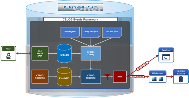
The CELOG bulk resolve workflow itself operates as follows:
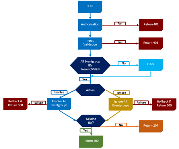
Both the WebUI and CLI route bulk event requests through the isi_papi_d service, where the event occurrences handler orchestrates the overall operation. The handler begins by authenticating the request and validating the input, then verifies all provided event group IDs and filters out any that are invalid. Only confirmed IDs are allowed to proceed, and these are deterministically grouped and executed together within a single transaction. The workflow is initiated through a request to the bulk endpoint, and the remaining valid events are processed as part of one automated transaction. If all steps complete successfully, the API returns a success response; if any step fails, the transaction is rolled back and an appropriate error is returned. No additional configuration is required, as bulk resolution leverages the existing PUT API and follows the same authentication and permission model. When multiple event IDs are supplied as an array, the backend automatically processes them in bulk mode, without requiring feature flags, database changes, or service configuration updates.

Bulk event actions can be managed from the OneFS WebUI under ‘Cluster management > Events and alerts > Event group history’:
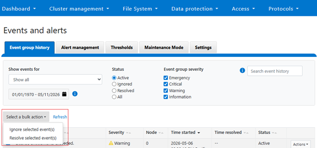
Multiple event groups can be selected and resolved or ignored as a single collective action:
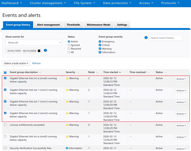
Or from the OneFS ClI using the following syntax:

# isi event groups bulk -–resolved true -–eventgroup_ids=<x,x,x,...>

After the action is confirmed, the WebUI submits the bulk request and processes it asynchronously in the background:
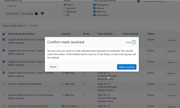
Upon successful completion of the bulk resolution operation, the WebUI displays a success banner to confirm the result:
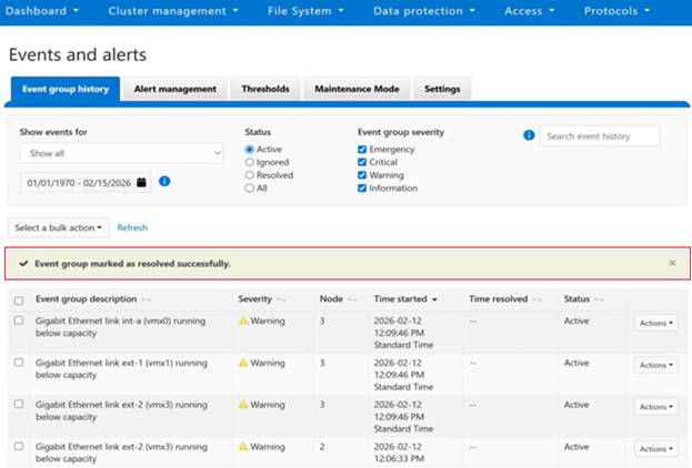
If the request includes invalid event IDs, those IDs are filtered out during validation, and the response clearly identifies which events were successfully resolved and which were skipped. For example, from the CLI:

# isi event groups bulk -–resolved true -–eventgroup_ids=55,56,250

Resolved event-groups: 55,56

Skipped event-groups: 250

#

By consolidating processing into a single atomic operation, redundant requests are eliminated, performance is improved, and consistent, reliable outcomes are maintained even under high‑load conditions. This approach delivers a faster experience for cluster administrators, increases overall system resilience, and simplifies end‑to‑end automation.

If a bulk request fails, begin by confirming that the payload includes a valid array of event IDs and that the appropriate permissions are in place. Next, review the API log messages at /var/log/isi_papi_d.log. Because execution is atomic for the validated set, any failure during processing triggers a rollback of the entire transaction, with the API response and logs providing clear indicators of the underlying cause.
OneFS SMB Durable Handles

Introduced in OneFS 9.14, Durable Handles are a feature of the SMB2 and SMB3 protocols in which, when a client opens a file, it receives an opaque file handle that can be marked as durable. A durable handle allows the open file state to survive a temporary client disconnect, such as a brief network glitch, transient cluster interruption, wi‑fi connectivity drop, or client sleep event, enabling the SMB client to reconnect and reclaim the same handle within a server-defined grace period. From the application’s perspective, the file remains open and normal I/O continues without errors or forced reopens. Durable handles are requested by the client at open time using specific CREATE request contexts, such as SMB2_CREATE_DURABLE_HANDLE_REQUEST and the corresponding reconnect variants.

Durable file handle support in OneFS 9.14 and later provides the following attributes and benefits:

Attribute Details
Availability Supported with SmartConnect static IP pools in OneFS 9.14.​
Client Supports v2 Durable Handles (SMB 3+ dialects)​.
Context Client can reconnect to the same file without losing its context​.
Cost Lightweight, avoiding the performance overhead of full Continuous Availability​.
Persistence Allows the cluster to keep the SMB file handle alive briefly​.

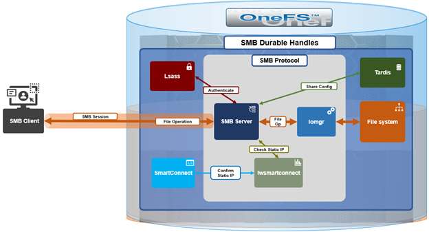
Under the hood, OneFS durable handles employ the following fundamental architecture:

At the protocol level, a durable handle is established when the client sends an SMB CREATE request that includes a durable handle create context. If the server and share configuration permit durable handles, the cluster’s SMB server marks the open accordingly and returns a persistent handle identifier along with a reconnect token, such as a create GUID, which can later be used to reclaim the handle. During normal operation, the client performs READ, WRITE, and locking operations using that handle over its SMB session.

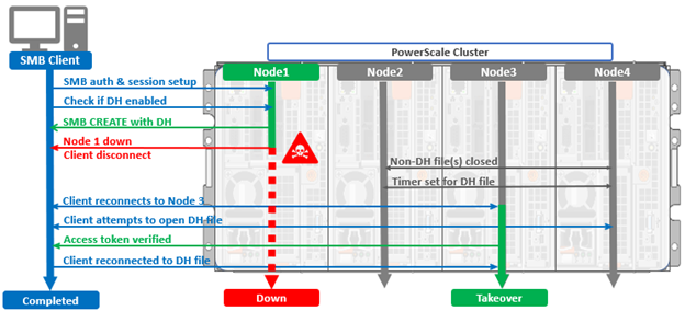
If the client disconnects unexpectedly and the underlying TCP connection and SMB session are lost, the cluster retains the durable handle’s state, including open and lock information, for a defined timeout period rather than closing it immediately. When the client reconnects, it reestablishes an SMB session and tree connection and issues a new CREATE request with a durable handle reconnect context that includes the original token:

If the cluster still holds the handle and the reconnect request matches, it rebinds the durable handle to the new session and I/O seamlessly resumes. If the client does not reconnect before the timeout expires, the cluster closes the open, releases any associated locks, and the handle can no longer be reclaimed.

As such, durable handles are intended to protect against short client-side outages and assume that the SMB server instance remains available. They do not survive a full-on SMB server and/or node failure unless additional high-availability mechanisms such are in place.

One such mechanism is SMB Continuous Availability (CA),a related and complimentary feature of the SMB3 protocol, which extends this model to provide high availability for clustered SMB file servers by allowing open file state and I/O to survive planned and unplanned server or node failovers.

Focus SMB Durable Handles SMB Continuous Availability
What Best-effort resilience to transient client connectivity issues while assuming the server remains running. Explicitly designed to tolerate server or node failures in a clustered environment.
How Stores open state locally for a limited time and is negotiated per file open. Requires share-level configuration and supporting cluster infrastructure to persist state across nodes.
Where General file access scenarios where brief network disruptions are expected, such as user desktops or laptops. CA shares are intended for critical workloads that demand uninterrupted access through failover events.
Version OneFS 9.14 onwards. OneFS 8.0 onwards.
Type Lighter weight, without the write-stability requirements of CA Uses persistent handles.
Performance Much lower performance impact. Higher performance cost due to stable write requirement.
Realm Granted only when client connects through a static IP pool in OneFS 9.14. Works with both dynamic and static IP pools.
Status Enabled by default. Disabled by default.

PowerScale has supported Continuous Availability since OneFS 8.0, and it is enabled at the share level by marking a share as continuously available, relying on persistent handle and lease state that is stored or replicated in a highly available, cluster-consistent manner. This allows the SMB server resource to move to another node during a failover while clients transparently reconnect and continue I/O without application disruption. CA combines persistent or durable v2 durable handles with clustering and witness mechanisms to coordinate reconnection and ensure strict data consistency semantics across nodes.

In practice, durable handles and SMB3 continuous availability differ in scope and guarantees. Durable handles provide best-effort resilience to transient client connectivity issues while assuming the server remains running, whereas CA is explicitly designed to tolerate server or node failures in a clustered environment. Durable handles store open state locally for a limited time and are negotiated per file open, while CA requires share-level configuration and supporting cluster infrastructure to persist state across nodes. As a result, durable handles are commonly used for general file access scenarios where brief network disruptions are expected, such as user desktops or laptops, while CA shares are intended for critical workloads like Hyper‑V or SQL Server over SMB that demand uninterrupted access through failover events.

On a PowerScale cluster running OneFS 9.14 or later, durable handles are supported as part of standard SMB2 and SMB3 operation to help clients recover from short connectivity disruptions. SMB3 continuous availability is provided through CA-enabled SMB shares, where OneFS ensures that file, handle, and share state are protected across service or node failovers within the cluster, allowing appropriately capable SMB3 clients to resume I/O transparently. As such, all CA shares make use of durable or persistent handle semantics internally, but durable handles alone do not imply continuous availability; CA represents a share-level, cluster-integrated high-availability capability, whereas durable handles are a file open resiliency mechanism.

Enabled by default in OneFS 9.14, durable file handles are only granted to clients that request them via an SMB session established from a static-IP SmartConnect network pool. Note that durable file handles on dynamic pools will be supported in a future OneFS release.

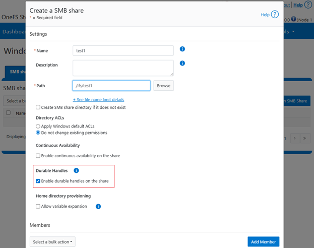
Durable handles can be configured on a per-share basis from the CLI, WebUI and platform API, as follows:

During creation:

# isi smb shares create --durable-handle-enabled <true | false>

Or from the OneFS WebUI under Protocols > Windows sharing (SMB) > SMB shares > Create a SMB share:

Durable handles support can modified on an existing share:

# isi smb shares modify --durable-handle-enabled <true | false>

A timeout can be configured with the ‘–ca-timeout’ flag, and the default duration is 120 seconds:

# isi smb shares create --durable-handle-enabled true --ca-timeout

As noted previously, SMB durable handles are enabled by default in OneFS 9.14:

# isi smb settings shares view | grep -i dura

Durable Handle Enabled: Yes

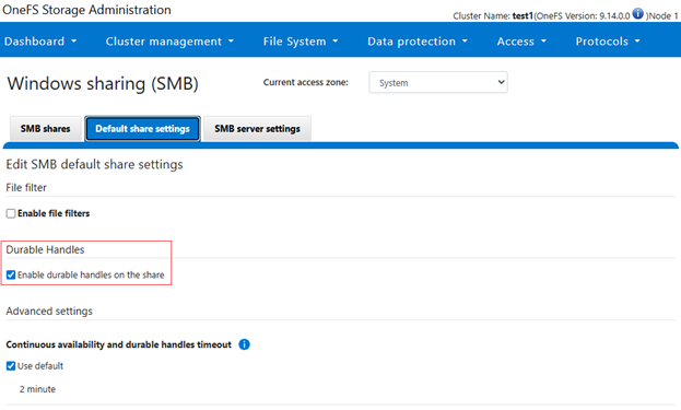
They can also be easily disabled globally as follows:

# isi smb settings shares modify --durable-handle-enabled 0

# isi smb settings shares view | grep -i dura

Durable Handle Enabled: No

Or from the WebUI under Protocols > Windows sharing (SMB) > Default share settings:

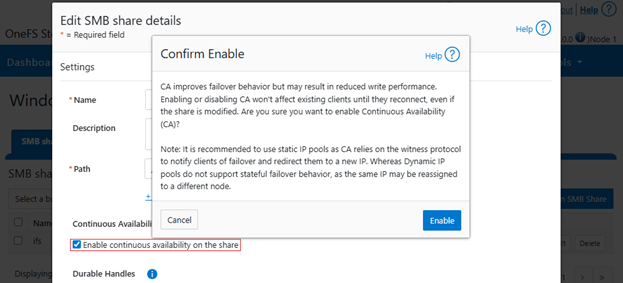
Additionally, Continuous Availability can also now be enabled or disabled on an existing share as follows:

# isi smb shares modify --continuously-available <true | false>

When enabling CA on a share, the following confirmation popup is displayed, advising of the potential write performance implications when activating Continuous Availability:

Note that, due to the IP allocation cache and timer of entry, a change in IP allocation method from dynamic to static or vice versa can potentially result in up to a five minute delay before durable handles configuration changes (enable or disable) are enacted.​

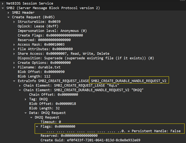
If and when it comes to investigating and troubleshooting durable handles, the /var/log/lwiod.log is a good place to start. ​Beyond that, network packet captures can also be extremely helpful at understanding and verifying the SMB sessions at a protocol request level. When examining a pcap of an SMB session with a network sniffing tool (e.g. Wireshark), the presence of the ‘SMB2_CREATE_DURABLE_HANDLE_REQUEST_V2’ request with a ‘Persistent Handle’ flag of value zero (“0”) indicates that this is a Durable Handle request:

Alternatively, if the persistent handle flag contains a value of one (“1”), this indicates that the request is for a persistent handle, with the likelihood that SMB CA is involved.

OneFS S3 Bucket Lifecycle Configuration and Use

As we saw in the previous article, OneFS 9.14 adds S3 Lifecycle Management, which allows administrators to define policies that automate object management within PowerScale S3 buckets. These policies enable the automatic deletion of objects based on criteria such as age, size, or key prefix and are applied uniformly to both existing and newly created objects in a bucket. Lifecycle processing is handled by the OneFS Job Engine, which runs daily to evaluate configured rules and generates per‑bucket tasks that traverse bucket directories and remove objects that meet the defined conditions.

To support this new functionality, the S3 API support in OneFS 9.14 and later now includes the following endpoints:

API Endpoint Description
PutBucketLifecycleConfiguration Sets the lifecycle configuration for the bucket and replaces any existing one. User must be the bucket owner to create the lifecycle configuration.
GetBucketLifecycleConfiguration Returns the current lifecycle configuration for the bucket. User must be the bucket owner to get the lifecycle configuration. Will return a ‘NoSuchLifecycleConfiguration’ error if a configuration is not found.​
DeleteBucketLifecycle Deletes the lifecycle configuration for the bucket. User must be the bucket owner to delete the lifecycle configuration.
AbortIncompleteMultipartUpload​
·         DaysAfterInitiation​ Number of days after the system aborts an incomplete MPU​.

Plus, the following S3 endpoints are also updated in 9.14 and require the following read and write permissions:

S3 Endpoint Read Permission Write Permission
CompleteMultiPartUpload x x
CopyObject x x
GetObject x
HeadObject x
PutObject x x

In this second article in the series, we’ll walk through a simple example demonstrating how to configure and validate S3 bucket lifecycle management in OneFS 9.14 and later releases.

To configure the feature, an S3 command must be sent to the cluster. A simple way to accomplish this without writing code is by using a utility like the ‘s3cmd’ tool. This tool provides a Python script which can be executed directly on a PowerScale cluster.

  1. The s3cmd tool’s zip file can be downloaded (or copied) to a directory on the cluster and unpacked with the following CLI command:
# unzip s3cmd-2.4.0.zip

Once unzipped, a new subdirectory named ‘s3cmd-2.4.0’ (with the corresponding version-specific suffix) is created. The working directory should be changed to this new subdirectory so that the ‘s3cmd’ script itself can be executed. The contents of the directory are as follows:

# ls

S3cmd-2.4.0     s3cmd-.2.4.0.zip

#cd s3cmd-2.4.0

# ls

INSTALL.md      NEWS            S3              s3cmd.egg-info

LICENSE         PKG-INFO        s3cmd           setup.cfg

MANIFEST.in     README.md       s3cmd.1         setup.py
  1. Next, a test bucket is configured on the cluster, and an access key and secret are generated for that bucket. In this example, the ‘root’ user and the ‘System’ multi-tenant access zone are used for access. This process begins by creating the test directory, verifying that the S3 service is enabled, and disabling HTTPS-only access.
# mkdir -p /ifs/s3lifecycle
# isi s3 settings global modify --service=true --https-only=false

Next, the bucket is created, in conjunction with the access key and secret. For example:

# isi s3 buckets create --name=s3life --path=/ifs/s3lifecycle --owner=root
# isi s3 keys create --user=root --force --show-key > /ifs/root-s3.keys
# isi s3 buckets list
Bucket Name  Path             Owner  Object ACL Policy  Object Lock Enabled  Lock Protection Mode  Description
---------------------------------------------------------------------------------------------------------------
s3life       /ifs/s3lifecycle root   replace            No                   -
---------------------------------------------------------------------------------------------------------------
Total: 1
# cat /ifs/root-s3.keys
       Access ID: 1_root_accid
      Secret Key: 0t1O0URz0H5pef6Wn6P6L9BKc8Ad
       Timestamp: 2026-05-14T14:27:36
  Old Secret Key: ****************************
Old Key Timestamp: 2026-05-12T17:25:02
  Old Key Expiry: 2026-05-14T14:37:36
  1. After obtaining the access ID and secret, s3cmd can be configured with these credentials and the appropriate endpoint parameters to simplify command execution. Site-specific configuration parameters that will need to be specified include:
  • Access Key
  • Secret Key
  • S3 Endpoint
  • DNS-style bucket+hostname:port

If HTTPS is preferred, the S3 endpoint port should be changed from 9020 to 9021, and Y should be selected when prompted to use the HTTPS protocol. HTTP may be used instead when packet‑level debugging is required, as it allows network sniffing tools such as Wireshark to capture traffic more efficiently and comprehensibly.

# python3 s3cmd --configure

Enter new values or accept defaults in brackets with Enter.
Refer to user manual for detailed description of all options.

Access key and Secret key are your identifiers for Amazon S3. Leave them empty for using the env variables.
Access Key: 1_root_accid
Secret Key: 0t1O0URz0H5pef6Wn6P6L9BKc8Ad
Default Region [US]:

Use "s3.amazonaws.com" for S3 Endpoint and not modify it to the target Amazon S3.
S3 Endpoint [s3.amazonaws.com]: 127.0.0.1:9020

Use "%(bucket)s.s3.amazonaws.com" to the target Amazon S3. "%(bucket)s" and "%(location)s" vars can be used
if the target S3 system supports dns based buckets.
DNS-style bucket+hostname:port template for accessing a bucket [%(bucket)s.s3.amazonaws.com]: s3://%(bucket)

Encryption password is used to protect your files from reading
by unauthorized persons while in transfer to S3
Encryption password:
Path to GPG program:

When using secure HTTPS protocol all communication with Amazon S3
servers is protected from 3rd party eavesdropping. This method is
slower than plain HTTP, and can only be proxied with Python 2.7 or newer
Use HTTPS protocol [Yes]: no

On some networks all internet access must go through a HTTP proxy.
Try setting it here if you can't connect to S3 directly
HTTP Proxy server name:

New settings:
 Access Key: 1_root_accid
 Secret Key: 0t1O0URz0H5pef6Wn6P6L9BKc8Ad
 Default Region: US
 S3 Endpoint: 127.0.0.1:9020
 DNS-style bucket+hostname:port template for accessing a bucket: s3://%(bucket)
 Encryption password:
 Path to GPG program: None
 Use HTTPS protocol: False
 HTTP Proxy server name:
 HTTP Proxy server port: 0

Test access with supplied credentials? [Y/n] y
Please wait, attempting to list all buckets...
Success. Your access key and secret key worked fine :-)

Now verifying that encryption works...
Not configured. Never mind.

Save settings? [y/N] y
Configuration saved to '/root/.s3cfg'
  1. Utilities such as the ubiquitous ‘dd’ CLI command are useful for easily and rapidly generating some test data files. Similarly, the ‘touch’ CLI command can be used to alter the ‘atime’ (last access) and ‘mtime’ (last modified) timestamps of these files. For example:
# dd if=/dev/zero of=/ifs/s3lifecycle/smlfl1 bs=1k count=1
# dd if=/dev/zero of=/ifs/s3lifecycle/smlfl2 bs=1k count=1
# touch -A -400000 /ifs/s3lifecycle/smlfl2*
# dd if=/dev/zero of=/ifs/s3lifecycle/bigfl1 bs=1M count=1
# dd if=/dev/zero of=/ifs/s3lifecycle/bigfl2 bs=1M count=1
# touch -A -250000 /ifs/s3lifecycle/big*
# dd if=/dev/zero of=/ifs/s3lifecycle/notrmv1 bs=1M count=1
# dd if=/dev/zero of=/ifs/s3lifecycle/notrmv2 bs=1M count=1

# ls -l /ifs/s3lifecycle/

total 4147
-rw-------     1 root  wheel  1048576 May 13 13:48 bigfl1
-rw-------     1 root  wheel  1048576 May 13 13:48 bigfl2
-rw-------     1 root  wheel  1048576 May 14 14:48 notrmv1
-rw-------     1 root  wheel  1048576 May 14 14:48 notrmv2
-rw-------     1 root  wheel     1024 May 12 22:48 smlfl1
-rw-------     1 root  wheel     1024 May 12 22:48 smlfl2
# date
Thu May 14 14:49:26 GMT 2026
 A total of six test files are created, two of which are 1 MB in size and have a modified time more than 1 day prior, two files that are 1 MiB in size but modified within 1 day, and two small 1 KB files with modification timestamps from 2 days prior.
  1. Next, add an XML, such as below, into a text file on the cluster. In the following example, the file is named /ifs/lifecycle.xml
<LifecycleConfiguration>
 <Rule>
   <Filter>
      <ObjectSizeGreaterThan>10000</ObjectSizeGreaterThan>
   </Filter>
   <Status>Enabled</Status>
   <Expiration>
     <Days>1</Days>
   </Expiration>
 </Rule>
</LifecycleConfiguration>

Once the XML request body has been added to the lifecycle.xml file, the ‘s3cmd’ can be run to ‘put’ the policy on the bucket. Once done, run a get lifecycle command to confirm that the policy has been applied correctly.

# python s3cmd setlifecycle /ifs/lifecycle.xml s3://s3life
s3://s3life/: Lifecycle Policy updated
onefs914-1# python s3cmd getlifecycle s3://s3life
<?xml version="1.0" ?>
<LifecycleConfiguration>
       <Rule>
               <Status>Enabled</Status>
               <Expiration>
                       <Days>1</Days>
               </Expiration>
               <Filter>
                       <ObjectSizeGreaterThan>10000</ObjectSizeGreaterThan>
               </Filter>
       </Rule>
</LifecycleConfiguration>
  1. Next, compare the data from pre and post S3Lifecycle job runs:
# ls /ifs/s3lifecycle
bigfl1        bigfl2        notrmv1       notrmv2       smlfl1       smlfl2
# isi job start S3Lifecycle
Started job [25]
# ls /ifs/s3lifecycle
notrmv 1       notrmv l2       smlfl1       smlfl2

After the S3Lifecycle job is initiated and allowed to run for a short period, the results show that two of the larger files have been deleted while the remaining files remain unchanged. This behavior is expected and reflects the configured expiration and filter criteria defined in the XML policy, under which only objects larger than 10,000 bytes and older than one day qualify for automatic deletion.

If and when it comes to investigating and troubleshooting S3 lifecycle, the following issues and possible resolutions may be useful:

Issue Background Potential Resolution
Unable to create lifecycle policy on bucket​ Bucket owner must be the same as directory owner​
Objects marked for deletion have not been deleted​ Ensure object or bucket does not have lock protection enabled​
Job for deletion has not been run​
Job for deletion is still in progress​

Beyond this, S3 operations are logged in the S3 log file ‘/var/log/s3.log’.​ Similarly, S3 Job Engine job operations and deleted objects are logged in ‘/var/log/isi_job_d_s3_lifecycle.log’.

OneFS S3 Bucket Lifecycle Management

Introduced in OneFS 9.14, the PowerScale S3 Lifecycle Management feature enables policy‑driven object management within PowerScale S3 buckets by supporting the automated deletion of objects based on administrator‑defined criteria such as object age, size, or key prefix. These lifecycle policies are applied consistently to both existing and newly created objects within a bucket. Backend processing is managed by the OneFS Job Engine, which performs daily evaluations of configured lifecycle rules and creates per‑bucket tasks to traverse bucket directories and remove objects that meet the specified conditions.

Newly introduced S3 API support in OneFS 9.14 and later includes the following endpoints:

API Endpoint Description
PutBucketLifecycleConfiguration Sets the lifecycle configuration for the bucket and replaces any existing one. User must be the bucket owner to create the lifecycle configuration.
GetBucketLifecycleConfiguration Returns the current lifecycle configuration for the bucket. User must be the bucket owner to get the lifecycle configuration. Will return a ‘NoSuchLifecycleConfiguration’ error if a configuration is not found.​
DeleteBucketLifecycle Deletes the lifecycle configuration for the bucket. User must be the bucket owner to delete the lifecycle configuration.

Additionally, the following S3 endpoints are also updated in the OneFS 9.14 release and require the following read and write permissions:

S3 Endpoint Read Permission Write Permission
CompleteMultiPartUpload x x
CopyObject x x
GetObject x
HeadObject x
PutObject x x

Note that all the above operations have an updated ‘x-amz-expiration’ response header if ‘objectexpiration’ has been configured. For example:

HTTP/1.1 200 OK​

…​

x-amz-expiration: expiry-date="Wed, 30 Apr 2027 00:00:00 GMT",rule-id=“3024"​

Content-Length: 434234​

Content-Type: text/plain

S3 bucket lifecycle behavior In OneFS 9.14 enables the bucket owner to define lifecycle management policies that are enforced using root‑level credentials. Lifecycle processing respects object lock protections, ensuring that immutable objects are preserved and not subject to deletion. Lifecycle rules may define expiration based on either a relative time period measured in days since the object’s last modification or an absolute date and timestamp, and can incorporate filtering criteria based on object size and key prefix, including support for backdated expiration rules. Each bucket supports a maximum of 1,000 lifecycle rules.

Note that the OneFS CLI, WebUI, or platform API do not currently support bucket lifecycle configuration, which can only be performed though the S3 API. Additionally, object tag–based filtering is not supported in OneFS 9.14, nor are object transition policies, ‘ExpiredObjectDeleteMarker’ configurations, noncurrent version expiration or transition rules, or versioned objects.

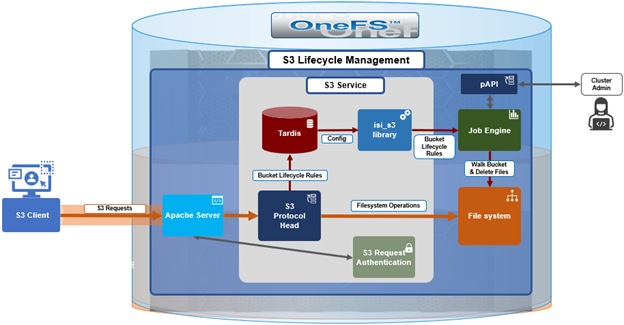
Under the hood, the core S3 bucket lifecycle management architecture is as follows:

At a high level, an S3 client sends a request containing the desired lifecycle rule(s), and the cluster’s S3 protocol head saves that into OneFS’ Tardis configuration database. The OneFS Job Engine retrieves the lifecycle configuration and then proceeds to walk the bucket and file structure, deleting files based upon the expressed rules.

The lifecycle processing is handled by the ‘S3Lifecycle’ job, which, by default, runs daily at 1:00 AM. Scheduling and priority for this job are optionally configurable through the OneFS CLI by a privileged local user:

# isi job types view S3Lifecycle

         ID: S3Lifecycl

Description: Manage S3 object lifecycle per bucket lifecycle policy.

    Enabled: Yes

     Policy: LOW

   Schedule: every day at 1:00am

   Priority: 6

During execution, the job logs all deleted objects and generates an S3Lifecycle job report, which can be viewed with the following OneFS CLI command:

# isi job reports view <job id>

Job report output is along the lines of the following:

S3Lifecycle[22] phase 1 (2026-04-30T11:18:06)​

---------------------------------------------​

Files 3​

Directories 1​

Apparent size 5300​

Physical size 52224​

Objects Deleted 2​

Objects Evaluated 3​

Objects No Action 1​

JE/Error Count 0​

JE/Time elapsed 3 seconds​

JE/Time working 3 seconds​

​

S3Lifecycle[22] Job Summary​

---------------------------​

Final Job State Succeeded​

Phase Executed

As above, this report summarizes the number of objects deleted and skipped, and logs detailed information about all deleted objects to /var/log/isi_job_d_s3_lifecycle.log.

The following table outlines the parameters that are supported for use within the lifecycle XML configuration body.

Configuration​ Description​
ID​ Unique identifier for the rule​.
Status​ If ‘Enabled’, the rule is currently being applied. If ‘Disabled’, the rule is not currently being applied. This is a mandatory field.​
Expiration​
  • Date​
Specifies expiration of the object in the form of date timestamp.​
  • Days​
Specifies expiration of the object in the form of days​.
Filter​
  • ObjectSizeGreaterThan​
Minimum object size to which the rule applies​.
  • ObjectSizeLessThan​
Maximum object size to which the rule applies​.
  • Prefix​
Prefix identifying one or more objects to which the rule applies.​
  • And​
Apply a logical ‘AND’ to two or more rules inside the operator​.

The ‘PutBucketLifecycleConfiguration’ request takes the following form:

PUT /?lifecycle HTTP/1.1​

Host: Bucket.s3.amazonaws.com​

x-amz-expected-bucket-owner: ExpectedBucketOwner​

<?xml version="1.0" encoding="UTF-8"?>​

<LifecycleConfiguration xmlns="http://s3.amazonaws.com/doc/2006-03-01/">​

    <Status>Enabled</Status>​

        <Rule>​

            …​

        </Rule>​

        <Rule>​

            …​

        </Rule>​

</LifecycleConfiguration>

As for the rules themselves, these can be temporal in nature. For example, expressing expiration as a date and/or time box:

<Rule>​

    <Expiration>​

    <Date>2029-03-02T12:30:00</Date>​

    <Days>365</Days>​

    </Expiration>​

</Rule>

The ‘date’ tag can be used to specify a time stamp, so objects in the bucket that exist during that date expression (for instance, 12:30 on March 2nd, 2029 in the example above) will be deleted. The ‘date’ tag can include a date in the past. In addition to an explicit date, a rule can also include a ‘days’ tag, which, in the example above, targets objects that haven’t been modified in 365 days, marking them for deletion.

Rules can also specify maximum and/or minimum object size in bytes. For example, greater than 1KB (1024) bytes but less than 50KB (51200 bytes):

<Rule>​

    <Filter>​

    <ObjectSizeGreaterThan>1024</ObjectSizeGreaterThan>​

    </Filter>​

<Rule>​

</Rule>​

    <Filter>​

    <ObjectSizeLessThan>51200</ObjectSizeLessThan>​

    </Filter>​

</Rule>​

Rules filters can also specify data locality. For example:

<Rule>​

<Filter>​

    <And>​

        <ObjectSizeGreaterThan>18124</ObjectSizeGreaterThan>​

        <ObjectSizeLessThan>92686</ObjectSizeLessThan>​

<Prefix>/data/path/</Prefix>​

    </And>​

</Filter>​

</Rule>

Note that, when specifying more than one filter, they must be wrapped in the <And> element, as above.

A bucket’s lifecycle configuration can be queried with the ‘GetBucketLifecycleConfiguration’ request. For example:

GET /?lifecycle HTTP/1.1​

Host: Bucket.s3.amazonaws.com​

x-amz-expected-bucket-owner: ExpectedBucketOwner

In contrast, a lifecycle can also be removed with the ‘DeleteBucketLifecycle’ request. For example:

DELETE /?lifecycle HTTP/1.1​

Host: Bucket.s3.amazonaws.com​

x-amz-expected-bucket-owner: ExpectedBucketOwner

In addition to bucket lifecycles, OneFS 9.14 also provides lifecycle management for incomplete S3 MPU operations. Specifically, this is the ability to craft lifecycle rules which clean up incomplete multipart uploads, helping reclaim space from abandoned large object transfers.

Configuration​ Description​
AbortIncompleteMultipartUpload​
  • DaysAfterInitiation​
Number of days after the system aborts an incomplete MPU​.

Rule parameters include the number of days after MPU initiation and the data path prefix. For example:

<Rule>​

    <AbortIncompleteMultipartUpload>​

        <DaysAfterInitiation>7</DaysAfterInitiation>​

    </AbortIncompleteMultipartUpload>​

<Filter>​

        <Prefix>/path/to/data/</Prefix>​

    </Filter>​

</Rule>

Note that the ‘DaysAfterInitiation’ parameter is limited in scope to incomplete multipart uploads (MPUs) and does not apply to standard objects or completed MPU uploads, while the lifecycle expiration rules similarly exclude incomplete MPUs.

In the next article in this series, we’ll look at some practical examples of how to configure, use, and validate S3 bucket lifecycle management in OneFS 9.14 and later releases.

OneFS Inline Compression Versus Incompressible Data

PowerScale OneFS inline compression is a native data reduction feature that operates in the write path to improve storage efficiency by compressing data before it is written to disk. This helps OneFS drive data reduction efficiencies to support PowerScale’s contract-backed 2:1 data reduction ratio (DRR) guarantee. Plus, many workloads and deployments achieving substantially higher ratios in practice, including EDA up to 6.5:1 compression and life sciences up to 4:1 compression.

As part of a multi-stage pipeline that includes zero-block elimination and inline deduplication, OneFS evaluates data in 128 KB regions and selectively compresses those that achieve useful space savings, storing them as compact encoded containers while leaving incompressible data unmodified.

Because this process occurs inline, it not only influences capacity utilization, but also CPU consumption, write latency, and on-disk data layout. When used with suitably compressible workloads, inline compression can significantly reduce physical I/O and increase effective cluster capacity. However, its impact on performance and data placement calls for understanding and careful consideration, particularly for workloads with low compressibility or frequent small updates.

Inline compression is often a beneficial optimization, with modest additional CPU overhead reducing physical I/O demands while increasing effective storage capacity. For many workloads, this expectation holds true. However, for incompressible data sets, enabling OneFS inline compression can negatively impact performance as compared to running with no compression at all, and the penalty doesn’t abate instantly upon disabling the feature.

So for data such as encrypted backups, already-compressed media, highly random content, or when randomly overwriting data that was previously written in a compressed layout, performance can degrade in ways that are predictable once the underlying on-disk activities are understood. The crux is that inline compression is not just a logical efficiency feature. It changes how data is laid out and how writes are handled. That means the impact is not limited to capacity savings, since it can also influence write throughput, overwrite behavior, and the cost of small updates into existing files.

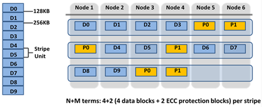
Without inline compression, OneFS stores data in 8 KB blocks, grouped into protection groups (e.g. 4+2 on a six node cluster/pool with a +2n FEC protection policy).

A 128 KB logical range (stripe unit) comprises 16 × 8 KB blocks laid out as plain data or parity blocks. Conversely, with inline data reduction enabled, every incoming write flows through a multi-stage pipeline before it ever touches disk:

Order Stage Description
1 Zero block removal Fully-zero 8 KB blocks are detected and stored as sparse references rather than real blocks.
2 Inline dedupe 8 KB blocks are fingerprinted and matched against an in-memory hash table; duplicates are collapsed to shared references.
3 Inline compression Surviving 128 KB regions are handed to the compression engine (zlib or lz4 depending on platform), which decides per-region whether the result is small enough to keep.
4 Protection and layout Whatever comes out the other side (compressed container, deduped reference, or plain blocks) is then protected with FEC and laid out across the cluster.

Note that every stage in this pipeline consumes cluster resources (CPU, etc) and adds write-path latency on every write – before OneFS knows whether it will deliver a benefit. Two things change on disk as a result:

  1. Data is chunked into 128 KB compression regions. Each region maps to 16 logical 8 KB blocks, and this is what the compression engine actually works on.
  2. Compressible regions are stored as compressed containers. When a 128 KB region compresses well enough, OneFS encodes it into a smaller bytestream using a node-specific algorithm (zlib, lz4, etc., fixed per platform and OneFS release). That region is no longer stored as 16 individual blocks, instead becoming a single compressed container.

Compressed regions are reported via the ‘isi get -DDO’ CLI command, as follows:

lbn 160: 10+2/2

...

5,5,1403920384:8192[DIRTY,COMPRESSED]#2

(sparse)[DIRTY,COMPRESSED]#3

...

{ebns={160,161},lbns={160,161,162,163,164},

encoded_size=10762,encoded_offset=0,

decoded_blocks=5,format=zlib}

The ‘encoded_size’ parameter returns the compressed byte count while ‘decoded_blocks’ reports how many logical 8 KB blocks live inside. The file looks identical from the outside, but, physically, the layout is where things get interesting since OneFS doesn’t know data is incompressible until it attempts to compress it. So even for data that will never compress, the engine still:

  1. Takes the 128 KB chunk.
  2. Runs it through the compression algorithm.
  3. Checks if compressing the chunk does save at least one full 8 KB block.
  4. Falls back to writing it as a chunk of normal, uncompressed 8 KB blocks.

On disk, those blocks show up tagged as ‘INCOMPRESSIBLE’. For example:

lbn 0: 10+2/2

...

6,2,1176543232:8192[DIRTY,INCOMPRESSIBLE]#16

...

1,5,1075085312:8192[DIRTY,INCOMPRESSIBLE]#12

No {encoded_size=…, decoded_blocks=…, format=…} stanza — just plain blocks. But the cluster still expended CPU and latency as a cost of trying. That overhead is real, and on CPU-constrained A-series archive nodes, it can show up directly in throughput.

That said, OneFS inline compression can be easily disabled entirely via the following CLI syntax:

# isi compression settings modify --enabled=False

With the ‘–enabled’ parameter set to ‘False’, new writes automatically skip the compression stage completely. Each 128 KB region goes straight to disk as plain 8 KB blocks — no attempt, no fallback, no overhead. The on-disk layout looks identical to the incompressible case above (without the INCOMPRESSIBLE tag), but the ‘attempted compression’ overhead never affected the write path.

However, note that disabling compression is not retroactive. Disabling compression afterwards doesn’t decompress or rewrite (re-lay-out) those regions in the background. That’s why you can disable compression cluster-wide and still see what looks like ‘compressed behavior’ on overwrites to older data. These regions can be identified by their ‘[COMPRESSED]’ tags and the compression metadata block in output from the ‘isi get -DDO’ CLI command.

With compression enabled, every write still flows through the full pipeline (zero-block removal > dedupe > compression) regardless of whether the data ends up compressed or uncompressed on disk. Hence, the latter case incurs  CPU overhead and write-path latency for no additional space savings.

On platforms like the PowerScale A310, this translates to a measurable throughput drop for workloads dominated by encrypted backups, already-compressed files, or just very random data. Disabling compression and re-running against fresh data will often result in write throughput increasing noticeably.

Note that the penalty for incompressible data is often more significant than for genuinely compressible or dedupe-able data. When data compresses or deduplicates well, inline data reduction actually reduces the amount of physical I/O hitting the drives, due to fewer blocks to write, less parity to compute, less backend traffic. The CPU overhead is more than offset by the I/O savings, resulting in better throughput and lower latency than without data reduction at all. In contrast, uncompressible data yields none of that I/O relief, but only the overhead.

When over-writing existing compressed data, a compressed region is a 128 KB atomic unit. This means that even a 4 KB update in the middle of a region will force OneFS to:

  1. Read the full 128 KB compressed container.
  2. Decompress it in memory.
  3. Merge the changed bytes.
  4. Re-encode and rewrite the full 128 KB region.

This read–decompress–modify–rewrite (R-DM-W) penalty applies even with inline compression disabled compression. If the region on disk was written compressed, the overwrite path still must treat it that way until the full file is physically rewritten with an uncompressed layout.

Even over-writing regions that are ‘incompressible’ incur an overhead. Because a file written with compression enabled may contain a mix of compressed and uncompressed (incompressible) regions, OneFS has to route partial-chunk overwrites through the compression stage to stay consistent across the 128 KB boundary. It can’t know ahead of time whether a given 128 KB range is fully uncompressed, so it has to treat the whole chunk conservatively.

This means that even ‘incompressible regions (i.e. data that never compressed in the first place) still carry a partial-overwrite penalty if compression was enabled when the file was initially written. Only a full 128 KB chunk replacement can safely bypass the compression engine entirely for that region, which is usually achieved by overwriting the file completely. This often manifests itself as:

  • New writes returning to full speed immediately upon disabling compression.
  • Overwrites remaining sluggish until the underlying data is physically rewritten as uncompressed — regardless of whether the on-disk blocks are tagged ‘[COMPRESSED]’ or ‘[INCOMPRESSIBLE]’.

Investigating and troubleshooting unexpected performance with inline compression typically involves:

  1. First, confirming whether the data is actually compressible by verifying data reduction statistics at the cluster or path level:
# isi statistics data-reduction view

# isi compression stats view

# isi_storage_efficiency /ifs/path/to/file

If compression is ‘enabled’ but little to no space savings are evident, the data almost certainly isn’t compressible.

  1. Next, check the actual on-disk layout:
# isi get -DDO /ifs/path/to/file

Specifically, the ratio of ‘[COMPRESSED]’ to ‘[INCOMPRESSIBLE]’ tags in the ‘PROTECTION GROUPS’ section, and the ‘Metatree logical blocks:’ summary at the end.

  1. Separate new writes from overwrites when testing:

This is the most important thing to get right when benchmarking. Use fresh test files written after any compression settings reconfiguration, and run tests in two distinct phases:

  • Phase 1 — Initial write (e.g. –overwrite=0 in fio)
  • Phase 2 — Overwrite / update (e.g. –overwrite=1 with random updates into the same files)

The following is a simple example ‘fio’ test overwriting an existing file at random offsets:

fio --name=random-update \

--filename=data.bin \

--rw=randwrite \

--bs=1M \

--size=10G \

--direct=1 \

--overwrite=1 \

--ioengine=libaio \

--iodepth=64

Then compare:

Test What it reveals
Initial writes: compression on vs. off The cost of the “try to compress” overhead
Overwrites into files written with compression on The R-DM-W penalty on legacy compressed regions
Overwrites into files written with compression off Your true baseline uncompressed overwrite performance
  1. Rule out unrelated bottlenecks.

Before assuming a compression issue, validate that the cluster is not hitting CPU, disk, or network limits for other reasons:

# isi statistics system list --nodes=all --format=top

# isi statistics drive list --format=top --sort=Queued

# isi statistics client list --format=top

# isi statistics protocol list --format=top

The goal is to distinguish between hitting the limits of the compression design from saturating the hardware. Having confirmed that legacy compressed layout is hurting performance, disabling compression, then physically rewriting the data is generally the cleanest approach. The following options can be used to ‘rehydrate’ the data back to a regular uncompressed layout.

1. Disable compression globally (or via file pool policy)

# isi compression settings modify --enabled=False

2. Or rewrite via intra-cluster copy using the ‘cp’ CLI command:

# cp -a /ifs/source/path /ifs/target/path

3. Use SyncIQ or SmartSync to replicate/copy to another /ifs location within the cluster.

Once rewritten, the ‘isi get -DDO’ CLI will show only uncompressed blocks, and overwrites follow the efficient block-level path rather than a read-decompress-modify-write (R-DM-W) operation.

4. If rewriting from the application is impractical, the SmartPoolsTree job can be used instead. Note that this method requires SmartPools to be licensed across the cluster, and the job settings configured as follows:

a) Set the SmartPoolsTree job to a ‘retune’ restriping strategy via gconfig:

# isi_gconfig -t job-config jobs.types.smartpoolstree.find_goal=retune

# isi_gconfig -t job-config jobs.types.smartpoolstree.restripe_goal=retune

b) Then run against the target path

# isi job start SmartPoolsTree --paths=/ifs/path/to/data

Or, for a more direct, non-job-engine approach, use isi set (no SmartPools license required):

# isi set -r -g retune /ifs/path/to/data

5. Alternatively, if SmartPools is unlicensed or using the job engine is undesirable, for a more direct, the ‘isi set’ CLI command can be used as follows:

# isi set -r -g retune /ifs/path/to/data

Note the case sensitivity of the ‘isi set’ ‘-r’ and ‘-R’ flags: The lowercase ‘-r’ flag forces an immediate restripe of the file using the specified goal (-g retune), effectively decompressing and re-laying-out the data without going through the job engine. The uppercase ‘-R’ flag applies the goal recursively to an entire directory tree, which can be an extremely time-consuming operation with little visibility or control over speed and duration. Scripting ‘isi set -r -g retune’ to iterate over a list of hot files or a specific subdirectory is typically preferred, providing improved control. Because this operation trades background I/O and capacity (by giving back compression savings), it’s best targeted at specific uncompressible or otherwise hot datasets rather than an entire archive tier.

Inline data reduction in OneFS can be highly beneficial for the appropriate workloads, but its underlying on-disk behavior can lead to unexpected outcomes if unfamiliar with its operation. Key takeaways include:

  • Incompressible data still incurs a compression cost when compression is enabled: CPU resources are consumed and write-path latency increases even when no actual space savings occur. In some cases, this overhead can be more impactful than with compressible data. When data compresses or deduplicates effectively, reduced I/O often offsets CPU usage and can even improve performance. With incompressible data, however, there are no such benefits—only added overhead.
  • Both compressed and incompressible regions are subject to read–decompress–modify–write (R-DM-W) overhead on every overwrite, regardless of the current compression setting.
  • Turning off compression benefits new writes right away, but it does not change the layout of data that was already written in a compressed format.
  • Data originally written as incompressible continues to experience 128 KB partial-chunk overhead during partial overwrites until those areas are either fully overwritten or the entire file is replaced.
  • A solid understanding of how OneFS implements data reduction—and a clear view of your workload characteristics before enabling it—helps avoid these pitfalls entirely.

As with many things in life, compression usage is a cost-benefit conundrum. Once the underlying mechanics are understood, their behavior is consistent and predictable. The key is to evaluate, measure, and quantify, and apply the knowledge and findings proactively, rather than reacting after performance issues arise in production.