OneFS GMP Scalability with Isi_Array_d

OneFS currently supports a maximum cluster size of 252 nodes, up from 144 nodes in releases prior to OneFS 8.2. To support this increase in scale, GMP transaction latency was dramatically improved by eliminating serialization and reducing its reliance on exclusive merge locks.

Instead, GMP now employs a shared merge locking model.

Take the four node cluster above. In this serialized locking example, the interaction between the two operations is condensed, illustrating how each node can finish its operation independent of its peers. Note that the diamond icons represent the ‘loopback’ messaging to node 1.

Each node takes its local exclusive merge lock. By not serializing/locking, the group change impact is significantly reduced, allowing OneFS to support greater node counts. It is expensive to stop GMP messaging on all nodes to allow this. While state is not synchronized immediately, it will be the same after a short while. The caller of a service change will not return until all nodes have been updated. Once all nodes have replied, the service change has completed. It is possible that multiple nodes change a service at the same time, or that multiple services on the same node change.

The example above illustrates nodes {1,2} merging with nodes {3, 4}. The operation is serialized, and the exclusive merge lock will be taken. In the diagram, the wide arrows represent multiple messages being exchanged. The green arrows show the new service exchange. Each node sends its service state to all the nodes new to it and receives the state from all new nodes. There is no need to send the current service state to any node in a group prior to the merge.

During a node split, there are no synchronization issues because either order results in the services being down, and the existing OneFS algorithm still applies.

OneFS 8.2 also saw the introduction of a new daemon, isi_array_d, which replaces isi_boot_d from prior versions. Isi_array_d is based on the Paxos consensus protocol.

Paxos is used to manage the process of agreeing on a single, cluster-wide result amongst a group of potential transient nodes. Although no deterministic, fault-tolerant consensus protocol can guarantee progress in an asynchronous network, Paxos guarantees safety (consistency), and the conditions that could prevent it from making progress are difficult to trigger.

In 8.2 and later, a unique GMP Cookie on each node in the cluster replaces the previous cluster-wide GMP ID. For example

  • # sysctl efs.gmp.group
  • gmp.group: <889a5e> (5) :{ 1-3:0-5, smb: 1-3, nfs: 1-3, all_enabled_protocols: 1-3, isi_cbind_d: 1-3 }

The GMP Cookie is a hexadecimal number. The initial value is calculated as a function of the current time, so it remains unique even after a node is rebooted. The cookie changes whenever there is a GMP event and is unique on power-up. In this instance, the (5) represents the configuration generation number.

In the interest of ease of readability in large clusters, logging verbosity is also reduced. Take the following syslog entry, for example:

2019-05-12T15:27:40-07:00 <0.5> (id1) /boot/kernel.amd64/kernel: connects: { { 1.7.135.(65-67)=>1-3 (IP), 0.0.0.0=>1-3, 0.0.0.0=>1-3, }, cfg_gen:1=>1-3, owv:{ build_version=0x0802009000000478 overrides=[ { version=0x08020000 bitmask=0x0000ae1d7fffffff }, { version=0x09000100 bitmask=0x0000000000004151 } ] }=>1-3, }

Only the lowest node number in a group proposes a merge or split to avoid too many retries from multiple proposing nodes.

GMP will always select nodes to merge to form the biggest group and equal size groups will be weighted towards the smaller node numbers. For example:

{1, 2, 3, 5} > {1, 2, 4, 5}

Discerning readers will have likely noticed a new ‘isi_cbind_d’ entry appended to the group sysctl output above. This new GMP service shows which nodes have connectivity to the DNS servers. For instance, in the following example node 2 is not communicating with DNS.

# sysctl efs.gmp.group

efs.gmp.group: <889a65> (5) :{ 1-3:0-5, smb: 1-3, nfs: 1-3, all_enabled_protocols: 1-3, isi_cbind_d: 1,3 }

As you may recall, isi_cbind_d is the distributed DNS cache daemon in OneFS. The primary purpose of cbind is to accelerate DNS lookups on the cluster, in particular for NFS, which can involve a large number of DNS lookups, especially when netgroups are used. The design of the cache is to distribute the cache and DNS workload among each node of the cluster.

Cbind has also also re-architected to improve its operation with large clusters. The primary change has been the introduction of a consistent hash to determine the gateway node to cache a request. This consistent hashing algorithm, which decides on which node to cache an entry, has been designed to minimize the number of entry transfers as nodes are added/removed. In so doing, it has also usefully reduced the number of threads and UDP ports used.

The cache is logically divided into two parts:

Component Description
Gateway cache The entries that this node will refresh from the DNS server.
Local cache The entries that this node will refresh from the Gateway node.


To illustrate cbind consistant hashing, consider the following three node cluster:

In the scenario above, when the cbind service on Node 3 becomes active, one third each of the gateway cache from node 1 and 2 respectively gets transferred to node 3.

Similarly, if node 3’s cbind service goes down, it’s gateway cache is divided equally between nodes 1 and 2.

For a DNS request on node 3, the node first checks its local cache. If the entry is not found, it will automatically query the gateway (for example, node 2). This means that even if node 3 cannot talk to the DNS server directly, it can still cache the entries from a different node.

Cluster Composition and GMP – Part 3

In the third and final of these articles on OneFS groups, we’ll take a look at what and how we can learn about a cluster’s state and transitions. Simply put, ‘group state’ is a list of nodes, drives and protocols which are participating in a cluster at a particular point in time.

Under normal operating conditions, every node and its requisite disks are part of the current group, and the group status can be viewed from any node in the cluster using the ‘sysctl efs.gmp.group’ CLI command. If a greater level of detail is desired, the syscl efs.gmp.current_info command will report extensive current GMP information.

When a group change occurs, a cluster-wide process writes a message describing the new group membership to /var/log/messages on every node. Similarly, if a cluster ‘splits’, the newly-formed sub-clusters behave in the same way: each node records its group membership to /var/log/messages. When a cluster splits, it breaks into multiple clusters (multiple groups). This is rarely, if ever, a desirable event. A cluster is defined by its group members. Nodes or drives which lose sight of other group members no longer belong to the same group and therefor no longer belong to the same cluster.

The ‘grep’ CLI utility can be used to view group changes from one node’s perspective, by searching /var/log/messages for the expression ‘new group’. This will extract the group change statements from the logfile. The output from this command may be lengthy, so can be piped to the ‘tail’ command to limit it the desired number of lines.

Please note that, for the sake of clarity, the protocol information has been removed from the end of each group string in all the following examples. For example:

{ 1-3:0-11, smb: 1-3, nfs: 1-3, hdfs: 1-3, all_enabled_protocols: 1-3, isi_cbind_d: 1-3, lsass: 1-3, s3: 1-3 }


Will be represented as:


{ 1-3:0-11 }


In the following example, the ‘tail -10’ command limits the outputted list to the last ten group changes reported in the file:

tme-1# grep -i ‘new group’ /var/log/messages | tail –n 10

2020-06-15-T08:07:50 -04:00 <0.4> tme-1 (id1) /boot/kernel.amd64/kernel: [gmp_info.c:1863] (pid 1814=”kt: gmp-drive-updat”) new group: : { 1:0-4, down: 1:5-11, 2-3 }

2020-06-15-T08:07:50 -04:00 <0.4> tme-1 (id1) /boot/kernel.amd64/kernel: [gmp_info.c:1863] (pid 1814=”kt: gmp-drive-updat”) new group: : { 1:0-5, down: 1:6-11, 2-3 }

2020-06-15-T08:07:50 -04:00 <0.4> tme-1(id1) /boot/kernel.amd64/kernel: [gmp_info.c:1863] (pid 1814=”kt: gmp-drive-updat”) new group: : { 1:0-6, down: 1:7-11, 2-3 }

2020-06-15-T08:07:50 -04:00 <0.4> tme-1 (id1) /boot/kernel.amd64/kernel: [gmp_info.c:1863] (pid 1814=”kt: gmp-drive-updat”) new group: : { 1:0-7, down: 1:8-11, 2-3 }

2020-06-15-T08:07:50 -04:00 <0.4> tme-1 (id1) /boot/kernel.amd64/kernel: [gmp_info.c:1863] (pid 1814=”kt: gmp-drive-updat”) new group: : { 1:0-8, down: 1:9-11, 2-3 }

2020-06-15-T08:07:50 -04:00 <0.4> tme-1 (id1) /boot/kernel.amd64/kernel: [gmp_info.c:1863] (pid 1814=”kt: gmp-drive-updat”) new group: : { 1:0-9, down: 1:10-11, 2-3 }

2020-06-15-T08:07:50 -04:00 <0.4> tme-1 (id1) /boot/kernel.amd64/kernel: [gmp_info.c:1863] (pid 1814=”kt: gmp-drive-updat”) new group: : { 1:0-10, down: 1:11, 2-3 }

2020-06-15-T08:07:50 -04:00 <0.4> tme-1 (id1) /boot/kernel.amd64/kernel: [gmp_info.c:1863] (pid 1814=”kt: gmp-drive-updat”) new group: : { 1:0-11, down: 2-3 }

2020-06-15-T08:07:51 -04:00 <0.4> tme-1 (id1) /boot/kernel.amd64/kernel: [gmp_info.c:1863] (pid 1814=”kt: gmp-merge”) new group: : { 1:0-11, 3:0-7,9-12, down: 2 }

2020-06-15-T08:07:52 -04:00 <0.4> tme-1 (id1) /boot/kernel.amd64/kernel: [gmp_info.c:1863] (pid 1814=”kt: gmp-merge”) new group: : { 1-2:0-11, 3:0-7,9-12 }

All the group changes in this set happen within two seconds of each other, so it’s worth looking earlier in the logs prior to the incident being investigated.

Here are some useful data points that can be gleaned from the example above:

  1. The last line shows that the cluster’s nodes are operational belong to the group. No nodes or drives report as down or split. (At some point in the past, drive ID 8 on node 3 was replaced, but a replacement disk was subsequently added successfully.)
  2. Node 1 rebooted. In the first eight lines, each group change is adding back a drive on node 1 into the group, and nodes two and three are inaccessible. This occurs on node reboot prior to any attempt to join an active group and is indicative of healthy behavior.
  3. Nodes 3 forms a group with node 1 before node 2 does. This could suggest that node 2 rebooted while node 3 remained up.

A review of group changes from the other nodes’ logs should be able to confirm this. In this case node 3’s logs show:

tme-1# grep -i ‘new group’ /var/log/messages | tail -10

2020-06-15-T08:07:50 -04:00 <0.4> tme-3(id3) /boot/kernel.amd64/kernel: [gmp_info.c:1863] (pid 1814=”kt: gmp-drive-updat”) new group: : { 3:0-4, down: 1-2, 3:5-7,9-12 }

2020-06-15-T08:07:50 -04:00 <0.4> tme-3(id3) /boot/kernel.amd64/kernel: [gmp_info.c:1863] (pid 1814=”kt: gmp-drive-updat”)  new group: : { 3:0-5, down: 1-2, 3:6-7,9-12 }

2020-06-15-T08:07:50 -04:00 <0.4> tme-3(id3) /boot/kernel.amd64/kernel: [gmp_info.c:1863] (pid 1814=”kt: gmp-drive-updat”) new group: : { 3:0-6, down: 1-2, 3:7,9-12 }

2020-06-15-T08:07:50 -04:00 <0.4> tme-3(id3) /boot/kernel.amd64/kernel: [gmp_info.c:1863] (pid 1814=”kt: gmp-drive-updat”) new group: : { 3:0-7, down: 1-2, 3:9-12 }

2020-06-15-T08:07:50 -04:00 <0.4> tme-3(id3) /boot/kernel.amd64/kernel: [gmp_info.c:1863] (pid 1814=”kt: gmp-drive-updat”) new group: : { 3:0-7,9, down: 1-2, 3:10-12 }

2020-06-15-T08:07:50 -04:00 <0.4> tme-3(id3) /boot/kernel.amd64/kernel: [gmp_info.c:1863] (pid 1814=”kt: gmp-drive-updat”) new group: : { 3:0-7,9-10, down: 1-2, 3:11-12 }

2020-06-15-T08:07:50 -04:00 <0.4> tme-3(id3) /boot/kernel.amd64/kernel: [gmp_info.c:1863] (pid 1814=”kt: gmp-drive-updat”) new group: : { 3:0-7,9-11, down: 1-2, 3:12 }

2020-06-15-T08:07:50 -04:00 <0.4> tme-3(id3) /boot/kernel.amd64/kernel: [gmp_info.c:1863] (pid 1814=”kt: gmp-drive-updat”) new group: : { 3:0-7,9-12, down: 1-2 }

2020-06-15-T08:07:50 -04:00 <0.4> tme-3(id3) /boot/kernel.amd64/kernel: [gmp_info.c:1863] (pid 1828=”kt: gmp-merge”) new group: : { 1:0-11, 3:0-7,9-12, down: 2 }

2020-06-15-T08:07:52 -04:00 <0.4> tme-3(id3) /boot/kernel.amd64/kernel: [gmp_info.c:1863] (pid 1828=”kt: gmp-merge”) new group: : { 1-2:0-11, 3:0-7,9-12 }

Since node 3 rebooted at the same time, it’s worth checking node 2’s logs to see if it also rebooted simultaneously. In this instance, the logfiles confirm this. Given that all three nodes rebooted at once, it’s highly likely that this was a cluster-wide event, rather than a single-node issue. OneFS ‘software watchdog’ timeouts (also known as softwatch or swatchdog), for example, cause cluster-wide reboots. However, these are typically staggered rather than simultaneous reboots. The Softwatch process monitors the kernel and dumps a stack trace and/or reboots the node when the node is not responding. This helps protects the cluster from the impact of heavy CPU starvation and aids the issue detection and resolution process.

If a cluster experiences multiple, staggered group changes, it can be extremely helpful to construct a timeline of the order and duration in which nodes are up or down. This info can then be cross-referenced with panic stack traces and other system logs to help diagnose the root cause of an event.

For example, in the following log excerpt, a node cluster experiences six different node reboots over a twenty-minute period. These are the group change messages from node 14, which that stayed up the whole duration:

tme-14# grep -i ‘new group’ /var/log/messages

2020-06-10-T14:54:00 -04:00 <0.4> tme-14(id20) /boot/kernel.amd64/kernel: [gmp_info.c:1863] (pid 1060=”kt: gmp-merge”) new group: : { 1-2:0-11, 6-8, 9,13-15:0-11, 16:0,2-12, 17-18:0-11, 19-21, diskless: 6-8, 19-21 }

2020-06-15-T06:44:38 -04:00 <0.4> tme-14(id20) /boot/kernel.amd64/kernel: [gmp_info.c:1863] (pid 1060=”kt: gmp-split”) new group: : { 1-2:0-11, 6-8, 13-15:0-11, 16:0,2-12, 17- 18:0-11, 19-21, down: 9}

2020-06-15-T06:44:58 -04:00 <0.4> tme-14(id20) /boot/kernel.amd64/kernel: [gmp_info.c:1863] (pid 1066=”kt: gmp-split”) new group: : { 1:0-11, 6-8, 13-14:0-11, 16:0,2-12, 17- 18:0-11, 19-21, down: 2, 9, 15}

2020-06-15-T06:45:20 -04:00 <0.4> tme-14(id20) /boot/kernel.amd64/kernel: [gmp_info.c:1863] (pid 1066=”kt: gmp-split”) new group: : { 1:0-11, 6-8, 14:0-11, 16:0,2-12, 17-18:0- 11, 19-21, down: 2, 9, 13, 15}

2020-06-15-T06:47:09 -04:00 <0.4> tme-14(id20) /boot/kernel.amd64/kernel: [gmp_info.c:1863] (pid 1066=”kt: gmp-merge”) new group: : { 1:0-11, 6-8, 9,14:0-11, 16:0,2-12, 17- 18:0-11, 19-21, down: 2, 13, 15}

2020-06-15-T06:47:27 -04:00 <0.4> tme-14(id20) /boot/kernel.amd64/kernel: [gmp_info.c:1863] (pid 1066=”kt: gmp-split”) new group: : { 6-8, 9,14:0-11, 16:0,2-12, 17-18:0-11, 19-21, down: 1-2, 13, 15}

2020-06-15-T06:48:11 -04:00 <0.4> tme-14(id20) /boot/kernel.amd64/kernel: [gmp_info.c:1863] (pid 2102=”kt: gmp-split”) new group: : { 6-8, 9,14:0-11, 16:0,2-12, 17:0-11, 19- 21, down: 1-2, 13, 15, 18}

2020-06-15-T06:50:55 -04:00 <0.4> tme-14(id20) /boot/kernel.amd64/kernel: [gmp_info.c:1863] (pid 2102=”kt: gmp-merge”) new group: : { 6-8, 9,13-14:0-11, 16:0,2-12, 17:0-11, 19- 21, down: 1-2, 15, 18}

2020-06-15-T06:51:26 -04:00 <0.4> tme-14(id20) /boot/kernel.amd64/kernel: [gmp_info.c:1863] (pid 85396=”kt: gmp-merge”) new group: : { 2:0-11, 6-8, 9,13-14:0-11, 16:0,2-12, 17:0-11, 19-21, down: 1, 15, 18}

2020-06-15-T06:51:53 -04:00 <0.4> tme-14(id20) /boot/kernel.amd64/kernel: [gmp_info.c:1863] (pid 85396=”kt: gmp-merge”) new group: : { 2:0-11, 6-8, 9,13-15:0-11, 16:0,2-12, 17:0-11, 19-21, down: 1, 18}

2020-06-15-T06:54:06 -04:00 <0.4> tme-14(id20) /boot/kernel.amd64/kernel: [gmp_info.c:1863] (pid 85396=”kt: gmp-merge”) new group: : { 1-2:0-11, 6-8, 9,13-15:0-11, 16:0,2-12, 17:0-11, 19-21, down: 18}

2020-06-15-T06:56:10 -04:00 <0.4> tme-14(id20) /boot/kernel.amd64/kernel: [gmp_info.c:1863] (pid 2102=”kt: gmp-merge”) new group: : { 1-2:0-11, 6-8, 9,13-15:0-11, 16:0,2-12, 17-18:0-11, 19-21}

2020-06-15-T06:59:54 -04:00 <0.4> tme-14(id20) /boot/kernel.amd64/kernel: [gmp_info.c:1863] (pid 85396=”kt: gmp-split”) new group: : { 1-2:0-11, 6-8, 9,13-15,17-18:0-11, 19-21, down: 16}

2020-06-15-T07:05:23 -04:00 <0.4> tme-14(id20) /boot/kernel.amd64/kernel: [gmp_info.c:1863] (pid 1066=”kt: gmp-merge”) new group: : { 1-2:0-11, 6-8, 9,13-15:0-11, 16:0,2-12, 17-18:0-11, 19-21}

First, run the isi_nodes “%{name}: LNN %{lnn}, Array ID %{id}” to map the cluster’s node names to their respective Array IDs.

Before the cluster node outage event on June 15 there was a group change on June 10:

2020-06-10-T14:54:00 -04:00 <0.4> tme-14(id20) /boot/kernel.amd64/kernel: [gmp_info.c:1863] (pid 1060=”kt: gmp-merge”) new group: : { 1-2:0-11, 6-8, 9,13-15:0-11, 16:0,2-12, 17-18:0-11, 19-21, diskless: 6-8, 19-21 }

After that, all nodes came back online and the cluster could be considered healthy. The cluster contains nine X210s with twelve drives apiece and six diskless nodes (accelerators). The Array IDs now extend to 21, and Array IDs 3 through 5 and 10 through 12 are missing. This confirms that six nodes were added to or removed from the cluster.

So, the first event occurs at 06:44:38 on 15 June:

2020-06-15-T06:44:38 -04:00 <0.4> tme-14(id20) /boot/kernel.amd64/kernel: [gmp_info.c:1863] (pid 1060=”kt: gmp-split”) new group: : { 1-2:0-11, 6-8, 13-15:0-11, 16:0,2-12, 17- 18:0-11, 19-21, down: 9, diskless: 6-8, 19-21 }

Node 14 identifies Array ID 9 (LNN 6) as having left the group.

Next, twenty seconds later, two more nodes (2 & 15) are marked as offline:

2020-06-15-T06:44:58 -04:00 <0.4> tme-14(id20) /boot/kernel.amd64/kernel: [gmp_info.c:1863] (pid 1066=”kt: gmp-split”) new group: : { 1:0-11, 6-8, 13-14:0-11, 16:0,2-12, 17- 18:0-11, 19-21, down: 2, 9, 15, diskless: 6-8, 19-21 }

Twenty-two seconds later, another node goes offline:

2020-06-15-T06:45:20 -04:00 <0.4> tme-14(id20) /boot/kernel.amd64/kernel: [gmp_info.c:1863] (pid 1066=”kt: gmp-split”) new group: : { 1:0-11, 6-8, 14:0-11, 16:0,2-12, 17-18:0- 11, 19-21, down: 2, 9, 13, 15, diskless: 6-8, 19-21 }

At this point, four nodes (2,6,7, & 9) are marked as being offline:

Almost two minutes later, the previously down node (node 6) rejoins the group:

2020-06-15-T06:47:09 -04:00 <0.4> tme-14(id20) /boot/kernel.amd64/kernel: [gmp_info.c:1863] (pid 1066=”kt: gmp-merge”) new group: : { 1:0-11, 6-8, 9,14:0-11, 16:0,2-12, 17- 18:0-11, 19-21, down: 2, 13, 15, diskless: 6-8, 19-21 }

However, twenty-five seconds after node 6 comes back, node 1 leaves the group:

2020-06-15-T06:47:27 -04:00 <0.4> tme-14(id20) /boot/kernel.amd64/kernel: [gmp_info.c:1863] (pid 1066=”kt: gmp-split”) new group: : { 6-8, 9,14:0-11, 16:0,2-12, 17-18:0-11, 19-21, down: 1-2, 13, 15, diskless: 6-8, 19-21 }

Finally, the group returns to its original composition:

2020-06-15-T07:05:23 -04:00 <0.4> tme-14(id20) /boot/kernel.amd64/kernel: [gmp_info.c:1863] (pid 1066=”kt: gmp-merge”) new group: : { 1-2:0-11, 6-8, 9,13-15:0-11, 16:0,2-12, 17-18:0-11, 19-21, diskless: 6-8, 19-21 }

As such, a timeline of this cluster event could read:

  1. June 15 06:44:38 6 down
  2. June 15 06:44:58 2, 9 down (6 still down)
  3. June 15 06:45:20 7 down (2, 6, 9 still down)
  4. June 15 06:47:09 6 up (2, 7, 9 still down)
  5. June 15 06:47:27 1 down (2, 7, 9 still down)
  6. June 15 06:48:11 12 down (1, 2, 7, 9 still down)
  7. June 15 06:50:55 7 up (1, 2, 9, 12 still down)
  8. June 15 06:51:26 2 up (1, 9, 12 still down)
  9. June 15 06:51:53 9 up (1, 12 still down)
  10. June 15 06:54:06 1 up (12 still down)
  11. June 15 06:56:10 12 up (none down)
  12. June 15 06:59:54 10 down
  13. June 15 07:05:23 10 up (none down)

The next step would be to review the logs from the other nodes in the cluster for this time period and construct similar timeline. Once done, these can be distilled into one comprehensive, cluster-wide timeline.

Note: Before triangulating log events across a cluster, it’s important to ensure that the constituent nodes’ clocks are all synchronized. To check this, run the isi_for_array –q date command on all nodes and confirm that they match. If not, apply the time offset for a particular node to the timestamps of its logfiles.

Here’s another example of how to interpret a series of group events in a cluster. Consider the following group info excerpt from the logs on node 1 of the cluster:

2020-06-15-T18:01:17 -04:00 <0.4> tme-1(id1) /boot/kernel.amd64/kernel: [gmp_info.c:1863] (pid 5681=”kt: gmp-config”) new group: <1,270>: { 1:0-11, down: 2, 6-11, diskless: 6-8 }

2020-06-15-T18:02:05 -04:00 <0.4> tme-1(id1) /boot/kernel.amd64/kernel: [gmp_info.c:1863] (pid 5681=”kt: gmp-config”) new group: <1,271>: { 1-2:0-11, 6-8, 9-11:0-11, soft_failed: 11, diskless: 6-8 }

2020-06-15-T18:08:56 -04:00 <0.4> tme–1(id1) /boot/kernel.amd64/kernel: [gmp_info.c:1863] (pid 10899=”kt: gmp-split”) new group: <1,272>: { 1-2:0-11, 6-8, 9-10:0-11, down: 11, soft_failed: 11, diskless: 6-8 }

2020-06-15-T18:08:56 -04:00 <0.4> tme-1(id1) /boot/kernel.amd64/kernel: [gmp_info.c:1863] (pid 10899=”kt: gmp-config”) new group: <1,273>: { 1-2:0-11, 6-8, 9-10:0-11, diskless: 6-8}

2020-06-15-T18:09:49 -04:00 <0.4> tme-1(id1) /boot/kernel.amd64/kernel: [gmp_info.c:1863] (pid 10998=”kt: gmp-config”) new group: <1,274>: { 1-2:0-11, 6-8, 9-10:0-11, soft_failed: 10, diskless: 6-8 }

2020-06-15-T18:15:34 -04:00 <0.4> tme-1(id1) /boot/kernel.amd64/kernel: [gmp_info.c:1863] (pid 12863=”kt: gmp-split”) new group: <1,275>: { 1-2:0-11, 6-8, 9:0-11, down: 10, soft_failed: 10, diskless: 6-8 }

2020-06-15-T18:15:34 -04:00 <0.4> tme-1(id1) /boot/kernel.amd64/kernel: [gmp_info.c:1863] (pid 12863=”kt: gmp-config”) new group: <1,276>: { 1-2:0-11, 6-8, 9:0-11, diskless: 6-8 }

The timeline of events here can be interpreted as such:

  1. In the first line, node 1 has just rebooted: node 1 is up, and all other nodes that are part of the cluster are down. (Nodes with Array IDs 3 through 5 were removed from the cluster prior to this sequence of events.)
  2. The second line indicates that all the nodes have returned to the group, except for Array ID 11, which has been smartfailed.
  3. In the third line, Array ID 11 is both smartfailed but also offline.
  4. Moments later in the fourth line, Array ID 11 has been removed from the cluster entirely.
  5. Less than a minute later, the node with array ID 10 is smartfailed, and the same sequence of events occur.
  6. After the smartfail finishes, the cluster group shows node 10 as down, then removed entirely.

Because group changes document the cluster’s actual configuration from OneFS’ perspective, they’re a vital tool in understanding which devices the cluster considers available, and which devices the cluster considers as having failed, at a point in time. This information, when combined with other data from cluster logs, can provide a succinct but detailed cluster history, simplifying both debugging and failure analysis.

Cluster Composition and GMP – Part 2

As we saw in the first of these blog articles, in OneFS parlance a group is a list of nodes, drives and protocols which are currently participating in the cluster. Under normal operating conditions, every node and its requisite disks are part of the current group, and the group’s status can be viewed by running sysctl efs.gmp.group on any node of the cluster.

For example, on a three node cluster:

# sysctl efs.gmp.group

efs.gmp.group: <2,288>: { 1-3:0-11, smb: 1-3, nfs: 1-3, hdfs: 1-3, all_enabled_protocols: 1-3, isi_cbind_d: 1-3, lsass: 1-3, s3: 1-3’ }

So, OneFS group info comprises three main parts:

  • Sequence number: Provides identification for the group (ie.’ <2,288>’ )
  • Membership list: Describes the group (ie. ‘1-3:0-11’ )
  • Protocol list: Shows which nodes are supporting which protocol services (ie. { smb: 1-3, nfs: 1-3, hdfs: 1-3, all_enabled_protocols: 1-3, isi_cbind_d: 1-3, lsass: 1-3, s3: 1-3

Please note that, for the sake of ease of reading, the protocol information has been removed from each of the group strings in all the following examples.

If more detail is desired, the syscl efs.gmp.current_info command will report extensive current GMP information.

The membership list {1-3:0-11, … } represents our three node cluster, with nodes 1 through 3, each containing 12 drives, numbered zero through 11. The numbers before the colon in the group membership string represent the participating Array IDs, and the numbers after the colon are the Drive IDs.

Each node’s info is maintained in the /etc/ifs/array.xml file. For example, the entry for node 1 of the cluster above reads:

<device>

<port>5019</port>

<array_id>2</array_id>

<array_lnn>2</array_lnn>

<guid>0007430857d489899a57f2042f0b8b409a0c</guid>

<onefs_version>0x800005000100083</onefs_version>

<ondisk_onefs_version>0x800005000100083</ondisk_onefs_version>

<ipaddress name=”int-a”>192.168.76.77</ipaddress>

<status>ok</status>

<soft_fail>0</soft_fail>

<read_only>0x0</read_only>

<type>storage</type>

</device>

It’s worth noting that the Array IDs (or Node IDs as they’re also often known) differ from a cluster’s Logical Node Numbers (LNNs). LNNs are the numberings that occur within node names, as displayed by isi stat for example.

Fortunately, the isi_nodes command provides a useful cross-reference of both LNNs and Array IDs:

# isi_nodes “%{name}: LNN %{lnn}, Array ID %{id}”

node-1: LNN 1, Array ID 1

node-2: LNN 2, Array ID 2

node-3: LNN 3, Array ID 3

As a general rule, LNNs can be re-used within a cluster, whereas Array IDs are never recycled. In this case, node 1 was removed from the cluster and a new node was added instead:

node-1: LNN 1, Array ID 4

The LNN of node 1 remains the same, but its Array ID has changed to ‘4’. Regardless of how many nodes are replaced, Array IDs will never be re-used.

A node’s LNN, on the other hand, is based on the relative position of its primary backend IP address, within the allotted subnet range.

The numerals following the colon in the group membership string represent drive IDs that, like Array IDs, are also not recycled. If a drive is failed, the node will identify the replacement drive with the next unused number in sequence.

Unlike Array IDs though, Drive IDs (or Lnums, as they’re sometimes known) begin at 0 rather than at 1 and do not typically have a corresponding ‘logical’ drive number.

For example:

node-3# isi devices drive list

Lnn  Location  Device    Lnum  State   Serial

—————————————————–

3    Bay  1    /dev/da1  12    HEALTHY PN1234P9H6GPEX

3    Bay  2    /dev/da2  10    HEALTHY PN1234P9H6GL8X

3    Bay  3    /dev/da3  9     HEALTHY PN1234P9H676HX

3    Bay  4    /dev/da4  8     HEALTHY PN1234P9H66P4X

3    Bay  5    /dev/da5  7     HEALTHY PN1234P9H6GPRX

3    Bay  6    /dev/da6  6     HEALTHY PN1234P9H6DHPX

3    Bay  7    /dev/da7  5     HEALTHY PN1234P9H6DJAX

3    Bay  8    /dev/da8  4     HEALTHY PN1234P9H64MSX

3    Bay  9    /dev/da9  3     HEALTHY PN1234P9H66PEX

3    Bay 10    /dev/da10 2     HEALTHY PN1234P9H5VMPX

3    Bay 11    /dev/da11 1     HEALTHY PN1234P9H64LHX

3    Bay 12    /dev/da12 0     HEALTHY PN1234P9H66P2X

—————————————————–

Total: 12

Note that the drive in Bay 5 has an Lnum, or Drive ID, of 7, the number by which it will be represented in a group statement.

Drive bays and device names may refer to different drives at different points in time, and either could be considered a “logical” drive ID. While the best practice is definitely not to switch drives between bays of a node, if this does happen OneFS will correctly identify the relocated drives by Drive ID and thereby prevent data loss.

Depending on device availability, device names ‘/dev/da*’ may change when a node comes up, so cannot be relied upon to refer to the same device across reboots. However, Drive IDs and drive bay numbers do provide consistent drive identification.

Status info for the drives is kept in a node’s /etc/ifs/drives.xml file. Here’s the entry is for drive Lnum 0 on node Lnn 3, for example:

<logicaldrive number=”0″ seqno=”0″ active=”1″ soft-fail=”0″ ssd=”0″ purpose=”0″>66b60c9f1cd8ce1e57ad0ede0004f446</logicaldrive>

For efficiency and ease of reading, group messages combine the xml lists into a pair of numbers separated by dashes to make reporting more efficient and easier to read. For example  ‘ 1-3:0-11 ‘.

However, when a replacement disk (Lnum 12) is added to node 2, the list becomes:

{ 1:0-11, 2:0-1,3-12, 3:0-11 }.

Unfortunately, changes like these can make cluster groups trickier to read.

For example: { 1:0-23, 2:0-5,7-10,12-25, 3:0-23, 4:0-7,9-36, 5:0-35, 6:0-9,11-36 }

This describes a  cluster with two node pools. Nodes 1 to 3 contain 24 drives each, and nodes 4 through 6 are have 36 drives each. Nodes 1, 3, and 5 contain all their original drives, whereas node 2 has lost drives 6 and 11, and node 6 is missing drive 10.

Accelerator nodes are listed differently in group messages since they contain no disks to be part of the group. They’re listed twice, once as a node with no disks, and again explicitly as a ‘diskless’ node.

For example, nodes 11 and 12 in the following:

{ 1:0-23, 2,4:0-10,12-24, 5:0-10,12-16,18-25, 6:0-17,19-24, 7:0-10,12-24, 9-10:0-23, 11-12, diskless: 11-12 …}

Nodes in the process of SmartFailing are also listed both separately and in the regular group. For example, node 2 in the following:

{ 1-3:0-23, soft_failed: 2 …}

However, when the FlexProtect completes, the node will be removed from the group.

A SmartFailed node that’s also unavailable will be noted as both down and soft_failed. For example:

{ 1-3:0-23, 5:0-17,19-24, down: 4, soft_failed: 4 …}

Similarly, when a node is offline, the other nodes in the cluster will show that node as down:

{ 1-2:0-23, 4:0-23,down: 3 …}

Note that no disks for that node are listed, and that it doesn’t show up in the group.

If the node is split from the cluster—that is, if it is online but not able to contact other nodes on its back-end network—that node will see the rest of the cluster as down. Its group might look something like {6:0-11, down: 3-5,8-9,12 …} instead.

When calculating whether a cluster is below protection level, SmartFailed devices should be considered ‘in the group’ unless they are also down: a cluster with +2:1 protection with three nodes up but smartfailed does not pose an exceptional risk to data availability.

Like nodes, drives may be smartfailed and down, or smartfailed but available. The group statement looks similar to that for a smartfailed or down node, only the drive Lnum is also included. For example:

{ 1-4:0-23, 5:0-6,8-23, 6:0-17,19-24, down: 5:7, soft_failed: 5:7 }

indicates that node id 5 drive Lnum 7 is both SmartFailed and unavailable.

If the drive was SmartFailed but still available, the group would read:

{ 1-4:0-23, 5:0-6,8-23, 6:0-17,19-24, soft_failed: 5:7 }

When multiple devices are down, consolidated group statements can be tricky to read. For example, if node 1 was down, and drive 4 of node 3 was down, the group statement would read:

{ 2:0-11, 3:0-3,5-11, 4-5:0-11, down: 1, 3:4, soft_failed: 1, 3:4 }

As mentioned in the previous GMP blog article, OneFS has a read-only mode. Nodes in a read-only state are clearly marked as such in the group:

{ 1-6:0-8, soft_failed: 2, read_only: 3 }

Node 3 is listed both as a regular group member and called out separately at the end, because it’s still active. It’s worth noting that “read-only” indicates that OneFS will not write to the disks in that node. However, incoming connections to that node are still able write to other nodes in the cluster.

Non-responsive, or dead, nodes appear in groups when a node has been permanently removed from the cluster without SmartFailing the node. For example, node 11 in the following:

{ 1-5:0-11, 6:0-7,9-12, 7-10,12-14:0-11, 15:0-10,12, 16-17:0-11, dead: 11 }

Drives in a dead state include a drive number as well as a node number. For example:

{ 1:0-11, 2:0-9,11, 3:0-11, 4:0-11, 5:0-11, 6:0-11, dead: 2:10 }

In the event of a dead disk or node, the recommended course of action is to immediately start a FlexProtect and contact Isilon Support.

SmartFailed disks appear in a similar manner to other drive-specific states, and therefore include both an array ID and a drive ID. For example:

{ 1:0-11, 2:0-3,5-12, 3-4:0-11, 5:0-1,3-11, 6:0-11, soft_failed: 5:2 }

This shows drive 2 in node 5 to be SmartFailed, but still available. If the drive was physically unavailable or down, the group would show as:

{ 1:0-11, 2:0-3,5-12, 3-4:0-11, 5:0-1,3-11, 6:0-11, down: 5:2, soft_failed: 5:2 }

Stalled drives (drives that don’t respond) are marked as such, for example:

{ 1:0-2,4-11, 2-4:0-11, stalled: 1:3 }

When a drive becomes un-stalled, it simply returns to the group. In this case, the new group would return to:

{ 1-4:0-11 }

A group displays the sequence number between angle brackets. For example, <3,6>: { 1-3:0-11 }, the sequence number is <3,6>.

The first number within the sequence, in this case 3, identifies the node that initiated the most recent group change

In the case of a node leaving the group, the lowest-numbered node remaining in the cluster will initiate the group change and thus appear as the first number within the angle brackets. In the case of a node joining the group, the newly-joined node will initiate the change and thus will be the listed node. If the group change involved a single drive joining or leaving the group, the node containing that drive will initiate the change and thus will be the listed node.

The second piece of the group sequence number increases sequentially. The previous group would have had a 5 in this place; the next group should have a 7.

Rarely do we need to review sequence numbers, so long as they are increasing sequentially, and so long as they are initiated by either the lowest-numbered node, a newly-added node, or a node that removed a drive. The group membership contains the information that we most frequently require.

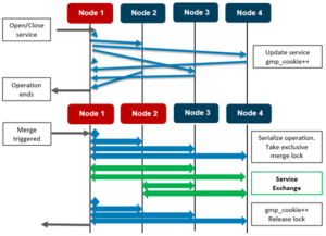
A group change occurs when an event changes devices participating in a cluster. These may be caused by drive removals or replacements, node additions, node removals, node reboots or shutdowns, backend (internal) network events, and the transition of a node into read-only mode. For debugging purposes, group change messages can be reviewed to determine whether any devices are currently in a failure state. We will explore this further in the next GMP blog article.


When a group change occurs, a cluster-wide process writes a message describing the new group membership to /var/log/messages on every node. Similarly, if a cluster “splits,” the newly-formed clusters behave in the same way: each node records its group membership to /var/log/messages. When a cluster splits, it breaks into multiple clusters (multiple groups). This is rarely, if ever, a desirable event. Notice that cluster and group are synonymous: a cluster is defined by its group members. Group members which lose sight of other group members no longer belong to the same group and thus no longer belong to the same cluster.

To view group changes from one node’s perspective, you can grep for the expression ‘new group’ to extract the group change statements from the log. For example:

tme-1# grep -i ‘new group’ /var/log/messages | tail –n 10

Nov 8 08:07:50 (id1) /boot/kernel/kernel: [gmp_info.c:530](pid 1814=”kt: gmpdrive-upda”) new group: : { 1:0-4, down: 1:5-11, 2-3 }

Nov 8 08:07:50 (id1) /boot/kernel/kernel: [gmp_info.c:530](pid 1814=”kt: gmpdrive-upda”) new group: : { 1:0-5, down: 1:6-11, 2-3 }

Nov 8 08:07:50 (id1) /boot/kernel/kernel: [gmp_info.c:530](pid 1814=”kt: gmpdrive-upda”) new group: : { 1:0-6, down: 1:7-11, 2-3 }

Nov 8 08:07:50 (id1) /boot/kernel/kernel: [gmp_info.c:530](pid 1814=”kt: gmpdrive-upda”) new group: : { 1:0-7, down: 1:8-11, 2-3 }

Nov 8 08:07:50 (id1) /boot/kernel/kernel: [gmp_info.c:530](pid 1814=”kt: gmpdrive-upda”) new group: : { 1:0-8, down: 1:9-11, 2-3 }

Nov 8 08:07:50 (id1) /boot/kernel/kernel: [gmp_info.c:530](pid 1814=”kt: gmpdrive-upda”) new group: : { 1:0-9, down: 1:10-11, 2-3 }

Nov 8 08:07:50 (id1) /boot/kernel/kernel: [gmp_info.c:530](pid 1814=”kt: gmpdrive-upda”) new group: : { 1:0-10, down: 1:11, 2-3 }

Nov 8 08:07:50 (id1) /boot/kernel/kernel: [gmp_info.c:530](pid 1814=”kt: gmpdrive-upda”) new group: : { 1:0-11, down: 2-3 }

Nov 8 08:07:51 (id1) /boot/kernel/kernel: [gmp_info.c:530](pid 1814=”kt: gmpmerge”) new group: : { 1:0-11, 3:0-7,9-12, down: 2 }

Nov 8 08:07:52 (id1) /boot/kernel/kernel: [gmp_info.c:530](pid 1814=”kt: gmpmerge”) new group: : {

In this case, the tail -10 command has been used to limit the returned group changes to the last ten reported in the file. All of these occur within two seconds, so in the case of an actual case, we would want to go further back, to before whatever incident was under investigation.

INTERPRETING GROUP CHANGES

Even in the example above, however, we can be sure of several things:

  • Most importantly, at last report all nodes of the cluster are operational and joined into the cluster. No nodes or drives report as down or split. (At some point in the past, drive ID 8 on node 3 was replaced, but a replacement disk has been added successfully.)
  • Next most important is that node 1 rebooted: for the first eight out of ten lines, each group change is adding back a drive on node 1 into the group, and nodes two and three are inaccessible. This occurs on node reboot prior to any attempt to join an active group and is correct and healthy behavior.
  • Note also that node 3 joins in with node 1 before node 2 does. This might be coincidental, given that the two nodes join within a second of each other. On the other hand, perhaps node 2 also rebooted while node 3 remained up. A review of group changes from these other nodes could confirm either of those behaviors.

Logging onto node 3, we can see the following:

tme-1# grep -i ‘new group’ /var/log/messages | tail -10

Jul 8 08:07:50 (id3) /boot/kernel/kernel: [gmp_info.c:530](pid 1828=”kt: gmpdrive-upda”) new group: : { 3:0-4, down: 1-2, 3:5-7,9-12 }

Jul 8 08:07:50 (id3) /boot/kernel/kernel: [gmp_info.c:530](pid 1828=”kt: gmpdrive-upda”) new group: : { 3:0-5, down: 1-2, 3:6-7,9-12 }

Jul 8 08:07:50 (id3) /boot/kernel/kernel: [gmp_info.c:530](pid 1828=”kt: gmpdrive-upda”) new group: : { 3:0-6, down: 1-2, 3:7,9-12 }

Jul 8 08:07:50 (id3) /boot/kernel/kernel: [gmp_info.c:530](pid 1828=”kt: gmpdrive-upda”) new group: : { 3:0-7, down: 1-2, 3:9-12 }

Jul 8 08:07:50 (id3) /boot/kernel/kernel: [gmp_info.c:530](pid 1828=”kt: gmpdrive-upda”) new group: : { 3:0-7,9, down: 1-2, 3:10-12 }

Jul 8 08:07:50 (id3) /boot/kernel/kernel: [gmp_info.c:530](pid 1828=”kt: gmpdrive-upda”) new group: : { 3:0-7,9-10, down: 1-2, 3:11-12 }

Jul 8 08:07:50 (id3) /boot/kernel/kernel: [gmp_info.c:530](pid 1828=”kt: gmpdrive-upda”) new group: : { 3:0-7,9-11, down: 1-2, 3:12 }

Jul 8 08:07:50 (id3) /boot/kernel/kernel: [gmp_info.c:530](pid 1828=”kt: gmpdrive-upda”) new group: : { 3:0-7,9-12, down: 1-2 }

Jul 8 08:07:50 (id3) /boot/kernel/kernel: [gmp_info.c:530](pid 1828=”kt: gmpmerge”) new group: : { 1:0-11, 3:0-7,9-12, down: 2 }

Jul 8 08:07:52 (id3) /boot/kernel/kernel: [gmp_info.c:530](pid 1828=”kt: gmpmerge”) new group: : { 1-2:0-11, 3:0-7,9-12 }

In this instance, it’s apparent that node 3 rebooted at the same time. It’s worth checking node 2’s logs to see if it also rebooted at the same time.

Given that all three nodes rebooted simultaneously, it’s highly likely that this was a cluster-wide event, rather than a single-node issue – especially since watchdog timeouts that cause cluster-wide reboots typically cause staggered rather than simultaneous reboots. The Softwatch process (also known as software watchdog or swatchdog) monitors the kernel and dumps a stack trace and/or reboots the node when the node is not responding. This tool protects the cluster from the impact of heavy CPU starvation and aids issue discovery and resolution process.

Constructing a timeline

If a cluster experiences multiple, staggered group changes, it can be extremely helpful to craft a timeline of the order and duration in which nodes are up or down. This timeline illustrates with. This info can be cross-referenced with panic stack traces and other system logs to help diagnose the root cause of an event.

For example, in the following a 15-node cluster experiences six different node reboots over a twenty-minute period. These are the group change messages from node 14, which that stayed up the whole duration:

tme-14# grep ‘new group’ tme-14-messages

Jul 8 16:44:38 tme-14(id20) /boot/kernel/kernel: [gmp_info.c:510](pid 1060=”kt: gmp-split”) new group: : { 1-2:0-11, 6-8, 13-15:0-11, 16:0,2-12, 17- 18:0-11, 19-21, down: 9}

Jul 8 16:44:58 tme-14(id20) /boot/kernel/kernel: [gmp_info.c:510](pid 1066=”kt: gmp-split”) new group: : { 1:0-11, 6-8, 13-14:0-11, 16:0,2-12, 17- 18:0-11, 19-21, down: 2, 9, 15}

Jul 8 16:45:20 tme-14(id20) /boot/kernel/kernel: [gmp_info.c:510](pid 1066=”kt: gmp-split”) new group: : { 1:0-11, 6-8, 14:0-11, 16:0,2-12, 17-18:0- 11, 19-21, down: 2, 9, 13, 15} Mar 26 16:47:09 tme-14(id20) /boot/kernel/kernel: [gmp_info.c:510](pid 1066=”kt: gmp-merge”) new group: : { 1:0-11, 6-8, 9,14:0-11, 16:0,2-12, 17- 18:0-11, 19-21, down: 2, 13, 15}

Jul 8 16:47:27 tme-14(id20) /boot/kernel/kernel: [gmp_info.c:510](pid 1066=”kt: gmp-split”) new group: : { 6-8, 9,14:0-11, 16:0,2-12, 17-18:0-11, 19-21, down: 1-2, 13, 15}

Jul 8 16:48:11 tme-14(id20) /boot/kernel/kernel: [gmp_info.c:510](pid 2102=”kt: gmp-split”) new group: : { 6-8, 9,14:0-11, 16:0,2-12, 17:0-11, 19- 21, down: 1-2, 13, 15, 18}

Jul 8 16:50:55 tme-14(id20) /boot/kernel/kernel: [gmp_info.c:510](pid 2102=”kt: gmp-merge”) new group: : { 6-8, 9,13-14:0-11, 16:0,2-12, 17:0-11, 19- 21, down: 1-2, 15, 18}

Jul 8 16:51:26 tme-14(id20) /boot/kernel/kernel: [gmp_info.c:510](pid 85396=”kt: gmp-merge”) new group: : { 2:0-11, 6-8, 9,13-14:0-11, 16:0,2-12, 17:0-11, 19-21, down: 1, 15, 18}

Jul 8 16:51:53 tme-14(id20) /boot/kernel/kernel: [gmp_info.c:510](pid 85396=”kt: gmp-merge”) new group: : { 2:0-11, 6-8, 9,13-15:0-11, 16:0,2-12, 17:0-11, 19-21, down: 1, 18}

Jul 8 16:54:06 tme-14(id20) /boot/kernel/kernel: [gmp_info.c:510](pid 85396=”kt: gmp-merge”) new group: : { 1-2:0-11, 6-8, 9,13-15:0-11, 16:0,2-12, 17:0-11, 19-21, down: 18}

Jul 8 16:56:10 tme-14(id20) /boot/kernel/kernel: [gmp_info.c:510](pid 2102=”kt: gmp-merge”) new group: : { 1-2:0-11, 6-8, 9,13-15:0-11, 16:0,2-12, 17-18:0-11, 19-21}

Jul 8 16:59:54 tme-14(id20) /boot/kernel/kernel: [gmp_info.c:510](pid 85396=”kt: gmp-split”) new group: : { 1-2:0-11, 6-8, 9,13-15,17-18:0-11, 19-21, down: 16}

Jul 8 17:05:23 tme-14(id20) /boot/kernel/kernel: [gmp_info.c:510](pid 1066=”kt: gmp-merge”) new group: : { 1-2:0-11, 6-8, 9,13-15:0-11, 16:0,2-12, 17-18:0-11, 19-21}

First, run the isi_nodes “%{name}: LNN %{lnn}, Array ID %{id}” to map the cluster’s node names to their respective Array IDs.

Before the cluster node outage event on Jul 8, we can see there was a group change on Jul 3

Jul 8 14:54:00 tme-14(id20) /boot/kernel/kernel: [gmp_info.c:510](pid 1060=”kt: gmp-merge”) new group: : { 1-2:0-11, 6-8, 9,13-15:0-11, 16:0,2-12, 17-18:0-11, 19-21, diskless: 6-8, 19-21 }

After that, all nodes came back online, and the cluster could be considered healthy. The cluster contains six accelerators, and all nine data nodes with twelve drives apiece. Since the Array IDs now extend to 21, and Array IDs 3 through 5 and 10 through 12 are missing, this confirms that six nodes were added or removed from the cluster.

So, the first event occurs at 16:44:38 on 8 July:

Jul 8 16:44:38 tme-14(id20) /boot/kernel/kernel: [gmp_info.c:510](pid 1060=”kt: gmp-split”) new group: : { 1-2:0-11, 6-8, 13-15:0-11, 16:0,2-12, 17- 18:0-11, 19-21, down: 9, diskless: 6-8, 19-21 }

Node 14 identifies Array ID 9 (LNN 6) as having left the group.

Next, twenty seconds later, two more nodes (2 & 15) show as offline:

Jul 8 16:44:58 tme-14(id20) /boot/kernel/kernel: [gmp_info.c:510](pid 1066=”kt: gmp-split”) new group: : { 1:0-11, 6-8, 13-14:0-11, 16:0,2-12, 17- 18:0-11, 19-21, down: 2, 9, 15, diskless: 6-8, 19-21 }

Twenty-two seconds later, another node goes offline:

Jul 8 16:45:20 tme-14(id20) /boot/kernel/kernel: [gmp_info.c:510](pid 1066=”kt: gmp-split”) new group: : { 1:0-11, 6-8, 14:0-11, 16:0,2-12, 17-18:0- 11, 19-21, down: 2, 9, 13, 15, diskless: 6-8, 19-21 }

At this point, four nodes (2,6,7, & 9) are marked as being offline:

Nearly two minutes later, the previously down node (node 6) rejoins:

Jul 8 16:47:09 tme-14(id20) /boot/kernel/kernel: [gmp_info.c:510](pid 1066=”kt: gmp-merge”) new group: : { 1:0-11, 6-8, 9,14:0-11, 16:0,2-12, 17- 18:0-11, 19-21, down: 2, 13, 15, diskless: 6-8, 19-21 }

Twenty-five seconds after node 6 comes back, however, node 1 goes offline:

Jul 8 16:47:27 tme-14(id20) /boot/kernel/kernel: [gmp_info.c:510](pid 1066=”kt: gmp-split”) new group: : { 6-8, 9,14:0-11, 16:0,2-12, 17-18:0-11, 19-21, down: 1-2, 13, 15, diskless: 6-8, 19-21 }

Finally, the group returns to the same as the original group:

Jul 8 17:05:23 tme-14(id20) /boot/kernel/kernel: [gmp_info.c:510](pid 1066=”kt: gmp-merge”) new group: : { 1-2:0-11, 6-8, 9,13-15:0-11, 16:0,2-12, 17-18:0-11, 19-21, diskless: 6-8, 19-21 }

As such, a timeline of this cluster event could read:

Jul 8 16:44:38 6 down

Jul 8 16:44:58 2, 9 down (6 still down)

Jul 8 16:45:20 7 down (2, 6, 9 still down)

Jul 8 16:47:09 6 up (2, 7, 9 still down)

Jul 8 16:47:27 1 down (2, 7, 9 still down)

Jul 8 16:48:11 12 down (1, 2, 7, 9 still down)

Jul 8 16:50:55 7 up (1, 2, 9, 12 still down)

Jul 8 16:51:26 2 up (1, 9, 12 still down)

Jul 8 16:51:53 9 up (1, 12 still down)

Jul 8 16:54:06 1 up (12 still down)

Jul 8 16:56:10 12 up (none down)

Jul 8 16:59:54 10 down

Jul 8 17:05:23 10 up (none down)

Before triangulating log events across multiple nodes, it’s important to ensure that the nodes’ clocks are all synchronized. To check this, run the isi_for_array –q date command on all nodes and confirm that they match. If not, apply the time offset for a particular node to the timestamps of its logfiles.

So what caused node 6 to go offline at 16:44:38? The messages file for that node show that nothing of note occurred between noon on Jul 8 and 16:44:31. After this, a slew of messages were logged:

Jul 8 16:44:31 tme-tme-6(id9) /boot/kernel/kernel: [rbm_device.c:749](pid 132=”swi5: clock sio”) ping failure (1)

Jul 8 16:44:31 tme-tme-6(id9) /boot/kernel/kernel: last 3 messages out: GMP_NODE_INFO_UPDATE, GMP_NODE_INFO_UPDATE, LOCK_REQ

Jul 8 16:44:31 tme-tme-6(id9) /boot/kernel/kernel: last 3 messages in : LOCK_RESP, TXN_COMMITTED, TXN_PREPARED

These three messages are repeated several times and then node 6 splits:

Jul 8 16:44:31 tme-tme-6(id9) /boot/kernel/kernel: [rbm_device.c:749](pid 132=”swi5: clock sio”) ping failure (21)

Jul 8 16:44:31 tme-tme-6(id9) /boot/kernel/kernel: last 3 messages out: GMP_NODE_INFO_UPDATE, GMP_NODE_INFO_UPDATE, LOCK_RESP

Jul 8 16:44:31 tme-6(id9) /boot/kernel/kernel: last 3 messages in : LOCK_REQ, LOCK_RESP, LOCK_RESP

Jul 8 16:44:34 tme-6(id9) /boot/kernel/kernel: [gmp_info.c:650](pid 48538=”kt: disco-cbs”) disconnected from node 1

Jul 8 16:44:34 tme-6(id9) /boot/kernel/kernel: [gmp_info.c:650](pid 49215=”kt: disco-cbs”) disconnected from node 2

Jul 8 16:44:34 tme-6(id9) /boot/kernel/kernel: [gmp_info.c:650](pid 50864=”kt: disco-cbs”) disconnected from node 6

Jul 8 16:44:34 tme-6(id9) /boot/kernel/kernel: [gmp_info.c:650](pid 49114=”kt: disco-cbs”) disconnected from node 7

Jul 8 16:44:34 tme-6(id9) /boot/kernel/kernel: [gmp_info.c:650](pid 30433=”kt: disco-cbs”) disconnected from node 8

Jul 8 16:44:34 tme-6(id9) /boot/kernel/kernel: [gmp_info.c:650](pid 49218=”kt: disco-cbs”) disconnected from node 13

Jul 8 16:44:34 tme-6(id9) /boot/kernel/kernel: [gmp_info.c:650](pid 50903=”kt: disco-cbs”) disconnected from node 14

Jul 8 16:44:34 tme-6(id9) /boot/kernel/kernel: [gmp_info.c:650](pid 24705=”kt: disco-cbs”) disconnected from node 15

Jul 8 16:44:34 tme-6(id9) /boot/kernel/kernel: [gmp_info.c:650](pid 48574=”kt: disco-cbs”) disconnected from node 16

Jul 8 16:44:34 tme-6(id9) /boot/kernel/kernel: [gmp_info.c:650](pid 49508=”kt: disco-cbs”) disconnected from node 17

Jul 8 16:44:34 tme-6(id9) /boot/kernel/kernel: [gmp_info.c:650](pid 52977=”kt: disco-cbs”) disconnected from node 18

Jul 8 16:44:34 tme-6(id9) /boot/kernel/kernel: [gmp_info.c:650](pid 52975=”kt: disco-cbs”) disconnected from node 19

Jul 8 16:44:34 tme-6(id9) /boot/kernel/kernel: [gmp_info.c:650](pid 50902=”kt: disco-cbs”) disconnected from node 20

Jul 8 16:44:34 tme-6(id9) /boot/kernel/kernel: [gmp_info.c:650](pid 48513=”kt: disco-cbs”) disconnected from node 21

Jul 8 16:44:34 tme-6(id9) /boot/kernel/kernel: [gmp_rtxn.c:194](pid 48513=”kt: gmp-split”) forcing disconnects from { 1, 2, 6, 7, 8, 13, 14, 15, 16, 17, 18, 19, 20, 21 }

Jul 8 16:44:50 tme-6(id9) /boot/kernel/kernel: [gmp_info.c:510](pid 48513=”kt: gmp-split”) new group: : { 9:0-11, down: 1-2, 6-8, 13-21, diskless: 6-8, 19-21 }

Node 6 splits from the rest of the nodes, then rejoins the rest of the cluster without a reboot.

Review messages logs for other nodes

After grabbing the pertinent node state and event info from the /var/log/messages logs for all fifteen nodes, a final timeline could read:

Jul 8 16:44:38 6 down

6: *** – split, not rebooted. Network issue? No engine stalls1 at that time…

Jul 8 16:44:58 2, 9 down (6 still down)

2: Softwatch timed out

9: Softwatch timed out

Jul 8 16:45:20 7 down (2, 6, 9 still down)

7: Indeterminate transactions

Jul 8 16:47:09 6 up (2, 7, 9 still down)

Jul 8 16:47:27 1 down (2, 7, 9 still down)

1: Softwatch timed out

Jul 8 16:48:11 12 down (1, 2, 7, 9 still down)

12: Softwatch timed out

Jul 8 16:50:55 7 up (1, 2, 9, 12 still down)

Jul 8 16:51:26 2 up (1, 9, 12 still down)

Jul 8 16:51:53 9 up (1, 12 still down)

Jul 8 16:54:06 1 up (12 still down)

Jul 8 16:56:10 12 up (none down)

Jul 8 16:59:54 10 down

10: Indeterminate transactions

Jul 8 17:05:23 10 up (none down)

Note: The BAM (block allocation manager) is responsible for building and executing a ‘write plan’ of which blocks should be written to which drives on which nodes for each transaction. OneFS logs an engine stall if this write plan encounters an unexpected delay.

Because group changes document the cluster’s actual configuration from OneFS’ perspective, they’re a vital tool in understanding at any point in time which devices the cluster considers available, and which devices the cluster considers as having failed. This info, when combined with other data from cluster logs, can provide a succinct but detailed cluster history, simplifying both debugging and failure analysis.

Dell EMC ECS IAM and Hadoop S3A Implementation

This paper describes basic information on IAM features with Dell EMC ECS and step by step process to configure ECS with AD FS to determine SAML support features, that allow the Hadoop administrator to setup access policies to control access to S3A Hadoop data.

https://www.dellemc.com/resources/en-us/asset/white-papers/products/storage/h18420-dell-emc-ecs-iam-and-hadoop-s3a-implementation.pdf


Cluster Composition and the OneFS GMP

By popular request, we’ll explore the topic of cluster state changes and quorum over the next couple of blog articles .

In computer science, Brewer’s CAP theorem states that it’s impossible for a distributed system to simultaneously guarantee consistency, availability, and partition tolerance. This means that, when faced with a network partition, one has to choose between consistency and availability.

OneFS does not compromise on consistency, so a mechanism is required to manage a cluster’s transient state and quorum.  As such, the primary role of the OneFS Group Management Protocol (GMP) is to help create and maintain a group of synchronized nodes. Having a consistent view of the cluster state is critical, since initiators need to know which node and drives are available to write to, etc. A group is a given set of nodes which have synchronized state, and a cluster may form multiple groups as connection state changes. GMP distributes a variety of state information about nodes and drives, from identifiers to usage statistics. The most fundamental of these is the composition of the cluster, or ‘static aspect’ of the group, which is stored in the array.xml file. The array.xml file also includes info such as the ID, GUID, and whether the node is diskless or storage, plus attributes not considered part of the static aspect, such as internal IP addresses.

Similarly, the state of a node’s drives is stored in the drives.xml file, along with a flag indicating whether the drive is an SSD. Whereas GMP manages node states directly, drive states are actually managed by the ‘drv’ module, and broadcast via GMP. A significant difference between nodes and drives is that for nodes, the static aspect is distributed to every node in the array.xml file, whereas drive state is only stored locally on a node. The array.xml information is needed by every node in order to define the cluster and allow nodes to form connections. In contrast, drives.xml is only stored locally on a node. When a node goes down, other nodes have no method to obtain the drive configuration of that node. Drive information may be cached by the GMP, but it is not available if that cache is cleared.

Conversely, ‘dynamic aspect’ refers to the state of nodes and drives which may change. These states indicate the health of nodes and their drives to the various file system modules – plus whether or not components can be used for particular operations. For example, a soft-failed node or drive should not be used for new allocations. These components can be in one of seven states:

  • UP The component is responding.
  • DOWN The component is not responding.
  • DEAD The component is not allowed to come back to the UP state and should be removed.
  • STALLED A drive is responding slowly.
  • GONE The component has been removed.
  • Soft-failed The component is in the process of being removed.
  • Read-only This state only applies to nodes.

Note: A node or drive may go from ‘down, soft-failed’ to ‘up, soft-failed’ and back. These flags are persistently stored in the array.xml file for nodes and the drives.xml file for drives.

Group and drive state information allows the various file system modules to make timely and accurate decisions about how they should utilize nodes and drives. For example, when reading a block, the selected mirror should be on a node and drive where a read can succeed (if possible). File system modules use the GMP to test for node and drive capabilities, which include:

  • Readable                 Drives on this node may be read.
  • Writable                  Drives on this node may be written to.
  • Restripe From      Move blocks away from the node.

Access levels help define ‘as a last resort’ with states for which access should be avoided unless necessary. The access levels, in order of increased access, are as follows:

  • Normal                     The default access level.
  • Read Stalled           Allows reading from stalled drives.
  • Modify Stalled      Allows writing to stalled drives.
  • Read Soft-fail       Allows reading from soft-failed nodes and drives.
  • Never                        Indicates a group state never supports the capability.

Drive state and node state capabilities are shown in the following tables. As shown, the only group states affected by increasing access levels are soft-failed and stalled.

 Minimum Access Level for Capabilities Per Node State

Node States Readable Writeable Restripe From
UP Normal Normal No
UP, Smartfail Soft-fail Never Yes
UP, Read-only Normal Never No
UP, Smartfail, Read-only Soft-fail Never Yes
DOWN Never Never No
DOWN, Smartfail Never Never Yes
DOWN, Read-only Never Never No
DOWN, Smartfail, Read-only Never Never Yes
DEAD Never Never Yes

Minimum Access Level for Capabilities Per Drive State

Drive States Minimum Access Level to Read Minimum Access Level to Write Restripe From
UP Normal Normal No
UP, Smartfail Soft-fail Never Yes
DOWN Never Never No
DOWN, Smartfail Never Never Yes
DEAD Never Never Yes
STALLED Read_Stalled Modify_Stalled No

OneFS depends on a consistent view of a cluster’s group state. For example, some decisions, such as choosing lock coordinators, are made assuming all nodes have the same coherent notion of the cluster.

Group changes originate from multiple sources, depending on the particular state. Drive group changes are initiated by the drv module. Service group changes are initiated by processes opening and closing service devices. Each group change creates a new group ID, comprising a node ID and a group serial number. This group ID can be used to quickly determine whether a cluster’s group has changed, and is invaluable for troubleshooting cluster issues, by identifying the history of group changes across the nodes’ log files.

GMP provides coherent cluster state transitions using a process similar to two-phase commit, with the up and down states for nodes being directly managed by the GMP. RBM or Remote Block Manager code provides the communication channel that connect devices in the OneFS. When a node mounts /ifs it initializes the RBM in order to connect to the other nodes in the cluster, and uses it to exchange GMP Info, negotiate locks, and access data on the other nodes.

Before /ifs is mounted, a ‘cluster’ is just a list of MAC and IP addresses in array.xml, managed by ibootd when nodes join or leave the cluster. When mount_efs is called, it must first determine what it‘s contributing to the file system, based on the information in drives.xml. After a cluster (re)boot, the first node to mount /ifs is immediately placed into a group on its own, with all other nodes marked down. As the Remote Block Manager (RBM) forms connections, the GMP merges the connected nodes, enlarging the group until the full cluster is represented. Group transactions where nodes transition to UP are called a ‘merge’, whereas a node transitioning to down is called a split. Several file system modules must update internal state to accommodate splits and merges of nodes. Primarily, this is related to synchronizing memory state between nodes.

The soft-failed, read-only, and dead states are not directly managed by the GMP. These states are persistent and must be written to array.xml accordingly. Soft-failed state changes are often initiated from the user interface, for example via the ‘isi devices’ command.

A GMP group relies on cluster quorum to enforce consistency across node disconnects. By requiring ⌊N/2⌋+1 replicas to be available, this ensures that no updates are lost. Since nodes and drives in OneFS may be readable, but not writable, OneFS has two quorum properties:

  • Read quorum
  • Write quorum

Read quorum is governed by having [N/2] + 1 nodes readable, as indicated by sysctl efs.gmp.has_quorum. Similarly, write quorum requires at least [N/2] + 1 writeable nodes, as represented by the sysctl efs.gmp.has_super_block_quorum. A group of nodes with quorum is called the ‘majority’ side, whereas a group without quorum is a ‘minority’. By definition, there can only be one ‘majority’ group, but there may be multiple ‘minority’ groups. A group which has any components in any state other than up is referred to as degraded.

File system operations typically query a GMP group several times before completing. A group may change over the course of an operation, but the operation needs a consistent view. This is provided by the group info, which is the primary interface modules use to query group state. The current group info can be viewed via the sysctl efs.gmp.current_info command. It includes the GMP’s group state, but also information about services provided by nodes in the cluster. This allows nodes in the cluster to discover when services change state on other nodes and take the appropriate action when this happens. An example is SMB lock expiry, which uses GMP service information to clean up locks held by other nodes when the service owning the lock goes down.

Processes change the service state in GMP by opening and closing service devices. A particular service will transition from down to up in the GMP group when it opens the file descriptor for a device. Closing the service file descriptor will trigger a group change that reports the service as down. A process can explicitly close the file descriptor if it chooses, but most often the file descriptor will remain open for the duration of the process and closed automatically by the kernel when it terminates.

An understanding of OneFS groups and their related group change messages allows you to determine the current health of a cluster – as well as reconstruct the cluster’s history when troubleshooting issues that involve cluster stability, network health, and data integrity. We’ll explore the reading and interpretation of group change status data in the second part of this blog article series.

HDP Upgrade and Transparent Data Encryption(TDE) support on Isilon OneFS 8.2

HDP Upgrade and Transparent Data Encryption support on Isilon OneFS 8.2

The objective of this testing is to demonstrate the Hortonworks HDP upgrade from HDP 2.6.5 to HDP 3.1 , during which Transparent Data Encryption(TDE) KMS keys and configuration are ported to OneFS Service from HDFS service after upgrade accurately, this facilitates Hadoop user to leverage TDE support on OneFS 8.2 straight out of the box after upgrade without any changes to the TDE/KMS configurations.

HDFS Transparent Data Encryption

The primary motivation of Transparent Data Encryption on HDFS is to support both end-to-end on wire and at rest encryption for data without any modification to the user application. The TDE scheme adds an additional layer of data protection by storing the decryption keys for files on a separate key management server. This separation of keys and data guarantees that even if the HDFS service is completely compromised the files cannot be decrypted without also compromising the keystore.

Concerns and Risks

The primary concern with TDE is mangling/losing Encrypted Data Encryption Keys (EDEKs) which are unique to each file in an Encryption Zone and are necessary to decrypt the data within. If this occurs, the customer’s data will be lost (DL). A secondary concern is managing Encryption Zone Keys (EKs) which are unique to each Encryption Zone and are associated with the root directory of each Zone. Losing/Mangling the EK would result in data unavailability (DU) for the customer and would require admin intervention to remedy. Finally, we need to make sure that EDEKs are not reused in anyway as this would weaken the security of TDE. Otherwise, there is little to no risk to existing or otherwise unencrypted data since TDE only works within Encryption Zones which are not currently supported.

Hortonworks HDP 2.6.5 on Isilon OneFS 8.2

To install HDP 2.6.5 on OneFS 8.2 by following the install guide.

Note: In install, the document is for OneFS 8.1.2 in which hdfs user is mapped to root in the Isilon setting, which is not required on OneFS 8.2, but need to create a new role to the hdfs user to backup/restore RWX access on the file system.

OneFS 8.2  [New Steps to be new role to the hdfs access zone]

hop-isi-dd-3# isi auth roles create --name=BackUpAdmin --description="Bypass FS permissions" --zone=hdp
hop-isi-dd-3# isi auth roles modify BackupAdmin --add-priv=ISI_PRIV_IFS_RESTORE --zone=hdp
hop-isi-dd-3# isi auth roles modify BackupAdmin --add-priv=ISI_PRIV_IFS_BACKUP --zone=hdp
hop-isi-dd-3# isi auth roles view BackUpAdmin --zone=hdp
Name: BackUpAdmin
Description: Bypass FS permissions
    Members: -
Privileges
ID: ISI_PRIV_IFS_BACKUP
      Read Only: True

ID: ISI_PRIV_IFS_RESTORE
      Read Only: True

hop-isi-dd-3# isi auth roles modify BackupAdmin --add-user=hdfs --zone=hdp


----- [ Optional:: Flush the auth mapping and cache to make hdfs take effect immediately]
hop-isi-dd-3# isi auth mapping flush --all
hop-isi-dd-3# isi auth cache flush --all
-----


1. After HDP 2.6.5 is installed on OneFS 8.2 following the install guide and above steps to add hdfs user backup/restore role. Install Ranger and Ranger KMS services, run service check on all the services to make sure the cluster is healthy and functional.


2. On the Isilon make sure hdfs access zone and hdfs user role are setup as required.

Isilon version

hop-isi-dd-3# isi version
Isilon OneFS v8.2.0.0 B_8_2_0_0_007(RELEASE): 0x802005000000007:Thu Apr  4 11:44:04 PDT 2019 root@sea-build11-04:/b/mnt/obj/b/mnt/src/amd64.amd64/sys/IQ.amd64.release   FreeBSD clang version 3.9.1 (tags/RELEASE_391/final 289601) (based on LLVM 3.9.1)
hop-isi-dd-3#
HDFS user role setup
hop-isi-dd-3# isi auth roles view BackupAdmin --zone=hdp
Name: BackUpAdmin
Description: Bypass FS permissions
Members: hdfs
Privileges
ID: ISI_PRIV_IFS_BACKUP
Read Only: True

ID: ISI_PRIV_IFS_RESTORE
Read Only: True
hop-isi-dd-3#


Isilon HDFS setting
hop-isi-dd-3# isi hdfs settings view --zone=hdp
Service: Yes
Default Block Size: 128M
Default Checksum Type: none
Authentication Mode: all
Root Directory: /ifs/data/zone1/hdp
WebHDFS Enabled: Yes
Ambari Server:
Ambari Namenode: kb-hdp-z1.hop-isi-dd.solarch.lab.emc.com
ODP Version:
Data Transfer Cipher: none
Ambari Metrics Collector: pipe-hdp1.solarch.emc.com
hop-isi-dd-3#


hdfs to root mapping removed from the access zone setting
hop-isi-dd-3# isi zone view hdp
Name: hdp
Path: /ifs/data/zone1/hdp
Groupnet: groupnet0
Map Untrusted:
Auth Providers: lsa-local-provider:hdp
NetBIOS Name:
User Mapping Rules:
Home Directory Umask: 0077
Skeleton Directory: /usr/share/skel
Cache Entry Expiry: 4H
Negative Cache Entry Expiry: 1m
Zone ID: 2
hop-isi-dd-3#

3. TDE Functional Testing

Primary Testing Foci

Reads and Writes: Clients with the correct permissions must always be able to reliably decrypt.

Kerberos Integration: Realistically, customers will not deploy TDE without Kerberos. [ In this testing Kerberos is not integrated]

TDE Configurations

HDFS TDE Setup
a. Create an encryption zone (EZ) key

Hadoop key create <keyname>

User “keyadmin” has privileges to create, delete, rollover, set key material, get, get keys, get metadata, generate EEK and Decrypt EEK. These privileges are controlled in Ranger web UI, login as keyadmin / <password> and setup these privileges.

[root@pipe-hdp1 ~]# su keyadmin
bash-4.2$ whoami
keyadmin

bash-4.2$ hadoop key create key_a
key_a has been successfully created with options Options{cipher='AES/CTR/NoPadding', bitLength=128, description='null', attributes=null}.
KMSClientProvider[http://pipe-hdp1.solarch.emc.com:9292/kms/v1/] has been updated.

bash-4.2$ hadoop key create key_a
key_a has been successfully created with options Options{cipher='AES/CTR/NoPadding', bitLength=128, description='null', attributes=null}.
KMSClientProvider[http://pipe-hdp1.solarch.emc.com:9292/kms/v1/] has been updated.

bash-4.2$
bash-4.2$ hadoop key list
Listing keys for KeyProvider: KMSClientProvider[http://pipe-hdp1.solarch.emc.com:9292/kms/v1/]
key_data
key_b
key_a
bash-4.2$
Note:: New Keys can also be created from Ranger KMS UI.


OneFS TDE Setup

a. Configure KMS URL in the Isilon OneFS CLI

isi hdfs crypto settings modify –kms-url=<url-string> –zone=<hdfs-zone-name> -v

isi hdfs crypto settings view –zone=<hdfs-zone-name>

hop-isi-dd-3# isi hdfs crypto settings view --zone=hdp
Kms Url: http://pipe-hdp1.solarch.emc.com:9292

hop-isi-dd-3#


b. Create a new directory in Isilon OneFS CLI under the Hadoop zone that needs to be encryption zone

mkdir /ifs/hdfs/<new-directory-name>

hop-isi-dd-3# mkdir /ifs/data/zone1/hdp/data_a

hop-isi-dd-3# mkdir /ifs/data/zone1/hdp/data_b
c. After new directory created, create encryption zone by assigning encryption key and directory path

isi hdfs crypto encryption-zones create –path=<new-directory-path> –key-name=<key-created-via-hdfs> –zone=<hdfs-zone-name> -v

hop-isi-dd-3# isi hdfs crypto encryption-zones create --path=/ifs/data/zone1/hdp/data_a --key-name=key_a --zone=hdp -v
Create encryption zone named /ifs/data/zone1/hdp/data_a, with key_a

hop-isi-dd-3# isi hdfs crypto encryption-zones create --path=/ifs/data/zone1/hdp/data_b --key-name=key_b --zone=hdp -v
Create encryption zone named /ifs/data/zone1/hdp/data_b, with key_b
NOTE:
    1. Encryption keys need to be created from hdfs client
    2. Need KMS store to manage keys example Ranger KMS
    3. Encryption zones can be created only on Isilon with CLI
    4. Creating an encryption zone from hdfs client fails with Unknown RPC RemoteException.

TDE Setup Validation

On HDFS Cluster

a. Verify the same from hdfs client   [Path is listed from the hdfs root dir]

hdfs crypto -listZones

bash-4.2$ hdfs crypto -listZones
/data_a  key_a
/data_b  key_b

On Isilon Cluster

a. List the encryption zones on Isilon                                            [Path is listed from the Isilon root path]

hdfs crypto -listZones

bash-4.2$ hdfs crypto -listZones
/data_a  key_a
/data_b  key_b


TDE Functional Testing

Authorize users to the EZ and KMS Keys

Ranger KMS UI

a. Login into Ranger KMS UI using keyadmin / <password>


b. Create 2 new policies to assign users (yarn, hive) to key_a and (mapred, hive) to key_b with the Get, Get Keys, Get Metadata, Generate EEK and Decrypt EEK permissions.


TDE HDFS Client Testing

a. Create sample files, copy it to respective EZs and access them from respective users.
/data_a EZ associated with key_a and only yarn, hive users have permissions
bash-4.2$ whoami
yarn
bash-4.2$ echo "YARN user test file, can you read this?" > yarn_test_file
bash-4.2$ rm -rf yarn_test_fil
bash-4.2$ hadoop fs -put yarn_test_file /data_a/
bash-4.2$ hadoop fs -cat /data_a/yarn_test_file
YARN user test file, can you read this?
bash-4.2$ whoami
yarn
bash-4.2$ exit
exit

[root@pipe-hdp1 ~]# su mapred
bash-4.2$ hadoop fs -cat /data_a/yarn_test_file
cat: User:mapred not allowed to do 'DECRYPT_EEK' on 'key_a'

bash-4.2$
/data_b EZ associated with key_b and only mapred, hive users have permissions
bash-4.2$ whoami
mapred
bash-4.2$ echo "MAPRED user test file, can you read this?" > mapred_test_file
bash-4.2$ hadoop fs -put mapred_test_file /data_b/
bash-4.2$ hadoop fs -cat /data_b/mapred_test_file
MAPRED user test file, can you read this?
bash-4.2$ exit
exit

[root@pipe-hdp1 ~]# su yarn
bash-4.2$ hadoop fs -cat /data_b/mapred_test_file
cat: User:yarn not allowed to do 'DECRYPT_EEK' on 'key_b'

bash-4.2$

User hive has permission to decrypt both keys i.e. ca access both EZs
USER user with decrypt privilege [HIVE]
[root@pipe-hdp1 ~]# su hive
bash-4.2$ pwd
/root
bash-4.2$ hadoop fs -cat /data_b/mapred_test_file
MAPRED user test file, can you read this?
bash-4.2$  hadoop fs -cat /data_a/yarn_test_file
YARN user test file, can you read this?
bash-4.2$


Sample distcp to copy data between EZs.
bash-4.2$ hadoop distcp -skipcrccheck -update /data_a/yarn_test_file /data_b/
19/05/20 21:20:02 INFO tools.DistCp: Input Options: DistCpOptions{atomicCommit=false, syncFolder=true, deleteMissing=false, ignoreFailures=false, overwrite=false, append=false, useDiff=false, fromSnapshot=null, toSnapshot=null, skipCRC=true, blocking=true, numListstatusThreads=0, maxMaps=20, mapBandwidth=100, sslConfigurationFile='null', copyStrategy='uniformsize', preserveStatus=[], preserveRawXattrs=false, atomicWorkPath=null, logPath=null, sourceFileListing=null, sourcePaths=[/data_a/yarn_test_file], targetPath=/data_b, targetPathExists=true, filtersFile='null', verboseLog=false}
19/05/20 21:20:03 INFO client.RMProxy: Connecting to ResourceManager at pipe-hdp1.solarch.emc.com/10.246.156.91:8050
19/05/20 21:20:03 INFO client.AHSProxy: Connecting to Application History server at pipe-hdp1.solarch.emc.com/10.246.156.91:10200
"""
"""
19/05/20 21:20:04 INFO mapreduce.Job: Running job: job_1558336274787_0003
19/05/20 21:20:12 INFO mapreduce.Job: Job job_1558336274787_0003 running in uber mode : false
19/05/20 21:20:12 INFO mapreduce.Job: map 0% reduce 0%
19/05/20 21:20:18 INFO mapreduce.Job: map 100% reduce 0%
19/05/20 21:20:18 INFO mapreduce.Job: Job job_1558336274787_0003 completed successfully
19/05/20 21:20:18 INFO mapreduce.Job: Counters: 33
File System Counters
FILE: Number of bytes read=0
FILE: Number of bytes written=152563
FILE: Number of read operations=0
FILE: Number of large read operations=0
FILE: Number of write operations=0
HDFS: Number of bytes read=426
HDFS: Number of bytes written=40
HDFS: Number of read operations=15
HDFS: Number of large read operations=0
HDFS: Number of write operations=4
Job Counters
Launched map tasks=1
Other local map tasks=1
Total time spent by all maps in occupied slots (ms)=4045
Total time spent by all reduces in occupied slots (ms)=0
Total time spent by all map tasks (ms)=4045
Total vcore-milliseconds taken by all map tasks=4045
Total megabyte-milliseconds taken by all map tasks=4142080
Map-Reduce Framework
Map input records=1
Map output records=0
Input split bytes=114
Spilled Records=0
Failed Shuffles=0
Merged Map outputs=0
GC time elapsed (ms)=91
CPU time spent (ms)=2460
Physical memory (bytes) snapshot=290668544
Virtual memory (bytes) snapshot=5497425920
Total committed heap usage (bytes)=196083712
File Input Format Counters
Bytes Read=272
File Output Format Counters
Bytes Written=0
org.apache.hadoop.tools.mapred.CopyMapper$Counter
BYTESCOPIED=40
BYTESEXPECTED=40
COPY=1
bash-4.2$
bash-4.2$ hadoop fs -ls /data_b/
Found 2 items
-rwxrwxr-x   3 mapred hadoop         42 2019-05-20 04:24 /data_b/mapred_test_file
-rw-r--r--   3 hive   hadoop         40 2019-05-20 21:20 /data_b/yarn_test_file
bash-4.2$ hadoop fs -cat /data_b/yarn_test_file
YARN user test file, can you read this?

bash-4.2$

Hadoop user without permission
bash-4.2$ hadoop fs -put test_file /data_a/
put: User:hdfs not allowed to do 'DECRYPT_EEK' on 'key_A'
19/05/20 02:35:10 ERROR hdfs.DFSClient: Failed to close inode 4306114529
org.apache.hadoop.ipc.RemoteException(java.io.FileNotFoundException): File does not exist: /data_a/test_file._COPYING_ (inode 4306114529)

TDE OneFS CLI Testing

EZ on Isilon EZ, no user has access to read the file
hop-isi-dd-3# whoami
root
hop-isi-dd-3# cat data_a/yarn_test_file

▒?Tm@DIc▒▒B▒▒>\Qs▒:[VzC▒▒Rw^<▒▒▒▒▒8H#


hop-isi-dd-3% whoami
yarn
hop-isi-dd-3% cat data_a/yarn_test_file

▒?Tm@DIc▒▒B▒▒>\Qs▒:[VzC▒▒Rw^<▒▒▒▒▒8H%

Upgrade the HDP to the latest version, following the upgrade process blog.

After upgrade make sure all the services are up running and pass the service check.

HDFS service will be replaced with OneFS service, under OneFS service configuration make sure KMS related properties are ported successfully.

Login into KMS UI and check the policies are intact after upgrade [ Note after upgrading new “Policy Labels” column added]


TDE validate existing configuration and keys after HDP 3.1 upgrade

TDE HDFS client testing existing configuration and keys

a. List the KMS provider and key to check they are intact after the upgrade
[root@pipe-hdp1 ~]# su hdfs
bash-4.2$ hadoop key list
Listing keys for KeyProvider: org.apache.hadoop.crypto.key.kms.LoadBalancingKMSClientProvider@2f54a33d
key_b
key_a
key_data

bash-4.2$ hdfs crypto -listZones
/data    key_data
/data_a  key_a
/data_b  key_b

b. Create sample files, copy it to respective EZs and access them from respective users
[root@pipe-hdp1 ~]# su yarn
bash-4.2$ cd
bash-4.2$ pwd
/home/yarn
bash-4.2$ echo "YARN user testfile after upgrade to hdp3.1, can you read this?" > yarn_test_file_2
bash-4.2$ hadoop fs -put yarn_test_file_2 /data_a/
bash-4.2$ hadoop fs -cat /data_a/yarn_test_file_2
YARN user testfile after upgrade to hdp3.1, can you read this?

bash-4.2$
[root@pipe-hdp1 ~]# su mapred
bash-4.2$ cd
bash-4.2$ pwd
/home/mapred
bash-4.2$ echo "MAPRED user testfile after upgrade to hdp3.1, can you read this?" > mapred_test_file_2
bash-4.2$ hadoop fs -put mapred_test_file_2 /data_b/
bash-4.2$ hadoop fs -cat /data_b/mapred_test_file_2
MAPRED user testfile after upgrade to hdp3.1, can you read this?

bash-4.2$
[root@pipe-hdp1 ~]# su yarn
bash-4.2$ hadoop fs -cat /data_b/mapred_test_file_2
cat: User:yarn not allowed to do 'DECRYPT_EEK' on 'key_b'

bash-4.2$
[root@pipe-hdp1 ~]# su hive
bash-4.2$ hadoop fs -cat /data_a/yarn_test_file_2
YARN user testfile after upgrade to hdp3.1, can you read this?

bash-4.2$ hadoop fs -cat /data_b/mapred_test_file_2
MAPRED user testfile after upgrade to hdp3.1, can you read this?

bash-4.2$
bash-4.2$ hadoop distcp -skipcrccheck -update /data_a/yarn_test_file_2 /data_b/
19/05/21 05:23:38 INFO tools.DistCp: Input Options: DistCpOptions{atomicCommit=false, syncFolder=true, deleteMissing=false, ignoreFailures=false, overwrite=false, append=false, useDiff=false, useRdiff=false, fromSnapshot=null, toSnapshot=null, skipCRC=true, blocking=true, numListstatusThreads=0, maxMaps=20, mapBandwidth=0.0, copyStrategy='uniformsize', preserveStatus=[BLOCKSIZE], atomicWorkPath=null, logPath=null, sourceFileListing=null, sourcePaths=[/data_a/yarn_test_file_2], targetPath=/data_b, filtersFile='null', blocksPerChunk=0, copyBufferSize=8192, verboseLog=false}, sourcePaths=[/data_a/yarn_test_file_2], targetPathExists=true, preserveRawXattrsfalse
19/05/21 05:23:38 INFO client.RMProxy: Connecting to ResourceManager at pipe-hdp1.solarch.emc.com/10.246.156.91:8050
19/05/21 05:23:38 INFO client.AHSProxy: Connecting to Application History server at pipe-hdp1.solarch.emc.com/10.246.156.91:10200
"
19/05/21 05:23:54 INFO mapreduce.Job: map 0% reduce 0%
19/05/21 05:24:00 INFO mapreduce.Job: map 100% reduce 0%
19/05/21 05:24:00 INFO mapreduce.Job: Job job_1558427755021_0001 completed successfully
19/05/21 05:24:00 INFO mapreduce.Job: Counters: 36
"
Bytes Copied=63
Bytes Expected=63
Files Copied=1

bash-4.2$ hadoop fs -ls /data_b/
Found 4 items
-rwxrwxr-x   3 mapred hadoop         42 2019-05-20 04:24 /data_b/mapred_test_file
-rw-r--r--   3 mapred hadoop         65 2019-05-21 05:21 /data_b/mapred_test_file_2
-rw-r--r--   3 hive   hadoop         40 2019-05-20 21:20 /data_b/yarn_test_file
-rw-r--r--   3 hive   hadoop         63 2019-05-21 05:23 /data_b/yarn_test_file_2

bash-4.2$ hadoop fs -cat /data_b/yarn_test_file_2
YARN user testfile after upgrade to hdp3.1, can you read this?

bash-4.2$ hadoop fs -cat /data_b/yarn_test_file_2
YARN user testfile after upgrade to hdp3.1, can you read this?

bash-4.2$
TDE OneFS client testing existing configuration and keys
a. List the KMS provider and key to check they are intact after upgrade
hop-isi-dd-3# isi hdfs crypto settings view --zone=hdp
Kms Url: http://pipe-hdp1.solarch.emc.com:9292
hop-isi-dd-3# isi hdfs crypto encryption-zones list
Path                       Key Name
------------------------------------
/ifs/data/zone1/hdp/data   key_data
/ifs/data/zone1/hdp/data_a key_a
/ifs/data/zone1/hdp/data_b key_b
------------------------------------
Total: 3

hop-isi-dd-3#
b. Permission to access previous created EZs
hop-isi-dd-3# cat data_b/yarn_test_file_2
3▒
▒{&▒{<N▒7▒      ,▒▒l▒n.▒▒▒bz▒6▒ ▒G▒_▒l▒Ieñ+
▒t▒▒N^▒ ▒# hop-isi-dd-3# whoami
root
hop-isi-dd-3#

TDE validate new configuration and keys after HDP 3.1 upgrade

TDE HDFS Client new keys setup

a. Create new keys and list
bash-4.2$ hadoop key create up_key_a
up_key_a has been successfully created with options Options{cipher='AES/CTR/NoPadding', bitLength=128, description='null', attributes=null}.
org.apache.hadoop.crypto.key.kms.LoadBalancingKMSClientProvider@11bd0f3b has been updated.

bash-4.2$ hadoop key create up_key_b
up_key_b has been successfully created with options Options{cipher='AES/CTR/NoPadding', bitLength=128, description='null', attributes=null}.
org.apache.hadoop.crypto.key.kms.LoadBalancingKMSClientProvider@11bd0f3b has been updated.

bash-4.2$ hadoop key list
Listing keys for KeyProvider: org.apache.hadoop.crypto.key.kms.LoadBalancingKMSClientProvider@2f54a33d
key_b
key_a
key_data
up_key_b
up_key_a

bash-4.2$

b. After EZs created from OneFS CLI check the zones reflect from HDFS client
bash-4.2$ hdfs crypto -listZones
/data       key_data
/data_a     key_a
/data_b     key_b
/up_data_a  up_key_a
/up_data_b  up_key_b


TDE OneFS Client new encryption zone setup

a. Create new EZ from OneFS CLI

HOP-ISI-DD-3# ISI HDFS CRYPTO ENCRYPTION-ZONES CREATE --PATH=/IFS/DATA/ZONE1/HDP/UP_DATA_A --KEY-NAME=UP_KEY_A --ZONE=HDP -V
Create encryption zone named /ifs/data/zone1/hdp/up_data_a, with up_key_a
hop-isi-dd-3# isi hdfs crypto encryption-zones create --path=/ifs/data/zone1/hdp/up_data_b --key-name=up_key_b --zone=hdp -v
Create encryption zone named /ifs/data/zone1/hdp/up_data_b, with up_key_b

hop-isi-dd-3# isi hdfs crypto encryption-zones list
Path                          Key Name
---------------------------------------
/ifs/data/zone1/hdp/data key_data
/ifs/data/zone1/hdp/data_a    key_a
/ifs/data/zone1/hdp/data_b    key_b
/ifs/data/zone1/hdp/up_data_a up_key_a
/ifs/data/zone1/hdp/up_data_b up_key_b
---------------------------------------
Total: 5

hop-isi-dd-3#

Create 2 new policies to assign users (yarn, hive) to up_key_a and (mapred, hive) to up_key_b with the Get, Get Keys, Get Metadata, Generate EEK and Decrypt EEK permissions.

TDE HDFS Client testing on upgraded HDP 3.1

a. Create sample files, copy it to respective EZs and access them from respective users

/up_data_a EZ associated with up_key_a and only yarn, hive users have permissions

[root@pipe-hdp1 ~]# su yarn
bash-4.2$ echo "After HDP Upgrade to HDP 3.1, YARN user, Creating this file" > up_yarn_test_file
bash-4.2$ hadoop fs -put up_yarn_test_file /up_data_a/
bash-4.2$ hadoop fs -cat /up_data_a/up_yarn_test_file
After HDP Upgrade to HDP 3.1, YARN user, Creating this file

bash-4.2$ hadoop fs -cat /up_data_b/up_mapred_test_file
cat: User:yarn not allowed to do 'DECRYPT_EEK' on 'up_key_b'
bash-4.2$

/up_data_b EZ associated with up_key_b and only mapred, hive users have permissions

[root@pipe-hdp1 ~]# su mapred
bash-4.2$ cd
bash-4.2$ echo "After HDP Upgrade to HDP 3.1, MAPRED user, Creating this file" > up_mapred_test_file
bash-4.2$ hadoop fs -put up_mapred_test_file /up_data_b/
bash-4.2$ hadoop fs -cat /up_data_b/up_mapred_test_file
After HDP Upgrade to HDP 3.1, MAPRED user, Creating this file

bash-4.2$


User hive has permission to decrypt both keys i.e. ca access both EZs

USER user with decrypt privilege [HIVE]

[root@pipe-hdp1 ~]# su hive
bash-4.2$ hadoop fs -cat /up_data_b/up_mapred_test_file
After HDP Upgrade to HDP 3.1, MAPRED user, Creating this file

bash-4.2$ hadoop fs -cat /up_data_a/up_yarn_test_file
After HDP Upgrade to HDP 3.1, YARN user, Creating this file
bash-4.2$


Sample distcp to copy data between EZs.

bash-4.2$ hadoop distcp -skipcrccheck -update /up_data_a/up_yarn_test_file /up_data_b/
19/05/22 04:48:21 INFO tools.DistCp: Input Options: DistCpOptions{atomicCommit=false, syncFolder=true, deleteMissing=false, ignoreFailures=false, overwrite=false, append=false, useDiff=false, useRdiff=false, fromSnapshot=null, toSnapshot=null, skipCRC=true, blocking=true, numListstatusThreads=0, maxMaps=20, mapBandwidth=0.0, copyStrategy='uniformsize', preserveStatus=[BLOCKSIZE], atomicWorkPath=null, logPath=null, sourceFileListing=null, sourcePaths=[/up_data_a/up_yarn_test_file], targetPath=/up_data_b, filtersFile='null', blocksPerChunk=0, copyBufferSize=8192, verboseLog=false}, sourcePaths=[/up_data_a/up_yarn_test_file], targetPathExists=true, preserveRawXattrsfalse
"
19/05/22 04:48:23 INFO mapreduce.Job: The url to track the job: http://pipe-hdp1.solarch.emc.com:8088/proxy/application_1558505736502_0001/
19/05/22 04:48:23 INFO tools.DistCp: DistCp job-id: job_1558505736502_0001
19/05/22 04:48:23 INFO mapreduce.Job: Running job: job_1558505736502_0001
"
Bytes Expected=60
Files Copied=1

bash-4.2$ hadoop fs -ls /up_data_b/
Found 2 items
-rw-r--r--   3 mapred hadoop         62 2019-05-22 04:43 /up_data_b/up_mapred_test_file
-rw-r--r--   3 hive   hadoop         60 2019-05-22 04:48 /up_data_b/up_yarn_test_file

bash-4.2$ hadoop fs -cat /up_data_b/up_yarn_test_file
After HDP Upgrade to HDP 3.1, YARN user, Creating this file

bash-4.2$

Hadoop user without permission

bash-4.2$ hadoop fs -put test_file /data_a/
put: User:hdfs not allowed to do 'DECRYPT_EEK' on 'key_A'
19/05/20 02:35:10 ERROR hdfs.DFSClient: Failed to close inode 4306114529
org.apache.hadoop.ipc.RemoteException(java.io.FileNotFoundException): File does not exist: /data_a/test_file._COPYING_ (inode 4306114529)


TDE OneFS CLI Testing

Permissions on Isilon EZ, no user has access to read the file
hop-isi-dd-3# cat up_data_a/up_yarn_test_file
%*݊▒▒ixu▒▒▒=}▒΁▒▒h~▒7▒=_▒▒▒0▒[.-$▒:/▒Ԋ▒▒▒▒\8vf▒{F▒Sl▒▒#


Conclusion

Above testing and results prove that HDP upgrade does not break and TDE configuration and same are ported to new OneFS service after a successful upgrade.

Exploring Hive LLAP using Testbench On OneFS

Short Description

Explore Hive LLAP by using Horontworks Testbench to generate data and run queries with LLAP enabled using HiveServer2 Interactive JDBC URL.

Article

The latest release of Isilon OneFS 8.1.2 delivers new capabilities and support like Apache Hadoop 3, Isilon Ambari Management pack, Apache Hive LLAP, Apache Ranger with SSL and WebHDFS. In this article, we shall explore Apache Hive LLAP using Horontworks Hive Testbench which supports LLAP. The Hive Testbench consists of a data generator and a standard set of queries typically used for benchmarking hive performance. This article describes how to generate data and run a query in beeline, with LLAP enabled.

If you don’t have a cluster already configured for LLAP, set up new HDP2.6 on Isilon OneFS from here and enable Interactive query under Ambari Server UI –> Hive –> Configs as below.

Hive Testbench setup

1. Log into the HDP client node where HIVE is installed.

2. Install and Setup Hive testbench

3. Generate 5GB of test data: [Here we shall use TPC-H Testbench]

  /If GCC not install/  yum install -y gcc

/If javac not found/ export JAVA_HOME=/usr/jdk64/jdk1.8.**** ;  export PATH=$JAVA_HOME/bin:$PATH

cd hive-testbench-hdp3/ sudo ./tpch-build.sh ./tpch-setup.sh 5


4. A MapReduce job runs to create the data and load the data into hive. This will take some time to complete. The last line in the script is:

Data loaded into database tpch_******.


Make sure all the below prerequisites are met before proceeding ahead.

1. HDP cluster up and running

2. YARN all services, Hive all services are up and running

3. Uid/gid parity and necessary directory structure maintained between HDP and OneFS

4. Interactive Query enabled.

5. Hive Testbench TPC-H database setup and data loaded.

Connecting to Interactive Service and running queries
Through Command Line

1. Log into the HDP client node where HIVE is installed and Hive Testbench setup.

2. Change to the directory where Hive Testbench is placed and into the sample-queries-tpch.

3. From Ambari Server Web UI –> HIVE Service –> Summary page, copy the HiveServer2 Interactive JDBC URL”


4. Run beeline with HiveServer2 Interactive JDBC URL with credential hive/hive.

beeline -n hive -p hive -u "jdbc:hive2://hawkeye03.kanagawa.demo:2181/;serviceDiscoveryMode=zooKeeper;zooKeeperNamespace=hiveserver2-hive2"

5. Run show databases command to check the tpch databases created during HIVE Testbench setup.

0: jdbc:hive2://hawkeye03.kanagawa.demo:2181/> show databases;

6. Switch to the tpch_flat_orc_5 databases

0: jdbc:hive2://hawkeye03.kanagawa.demo:2181/> use tpch_flat_orc_5;

7. Run the query7.sql by issuing run command as below and note down the execution time, let’s call this 1st run.

0: jdbc:hive2://hawkeye03.kanagawa.demo:2181/> !run query7.sql

To monitor LLAP functioning open HiveServer2 Interactive UI from the Ambari Server web UI –> Hive service –> Summary –> Quick Links –> HiveServer2 Interactive UI

Figure :: HiveServer2 Interactive UI

Now click on Running Instances Web URL(highlighted in above image) to go to LLAP Monitor page

On this LLAP Monitor UI, metrics to watch are Cache (use rate, Request count, Hit Rate) and System (LLAP open Files).


8. Immediate after step 7, which was 1st time query7.sql run, let us run the same query7.sql again and call it 2nd run. Monitor execution time, LLAP cache Metrics and System metrics.


Notice the drastic reduction in the execution time, with increase in Cache metrics.

9. Let us run the same query7.sql again, 3rd time.

Notice that the 2nd and 3rd run of the query7.sql completes much more quickly, this is because the LLAP cache fills with data, queries respond more quickly.

Summary

Hive LLAP combines persistent query servers and intelligent in-memory caching to deliver blazing-fast SQL queries without sacrificing the scalability Hive and Hadoop are known for. With OneFS 8.1.2 support for Hive LLAP the Hadoop cluster installed on OneFS benefit with LLAP feature for fast and interactive SQL on Hadoop with Hive LLAP. So benefits of Hive LLAP include LLAP uses persistent query servers to avoid long startup times and deliver fast SQL. Shares its in-memory cache among all SQL users, maximizing the use of this scarce resource. LLAP has fine-grained resource management and preemption, making it great for highly concurrent access across many users. LLAP is 100% compatible with existing Hive SQL and Hive tools.

Bigdata File Formats Support on DellEMC Isilon

This article describes the DellEMC Isilon’s support for Apache Hadoop file formats in terms of disk space utilization. To determine this, we will use Apache Hive service to create and store different file format tables and analyze the disk space utilization by each table on the Isilon storage.

Apache Hive supports several familiar file formats used in Apache Hadoop. Hive can load and query different data files created by other Hadoop components such as PIG, Spark, MapReduce, etc. In this article, we will check Apache Hive file formats such as TextFile, SequenceFIle, RCFile, AVRO, ORC and Parquet formats. Cloudera Impala also supports these file formats.

To begin with, let us understand a bit about these Bigdata File formats. Different file formats and compression codes work better for different data sets in Hadoop, the main objective of this article is to determine their supportability on DellEMC Isilon storage which is a scale-out NAS storage for Hadoop cluster.

Following are the Hadoop file formats

Test File: This is a default storage format. You can use the text format to interchange the data with another client application. The text file format is very common for most of the applications. Data is stored in lines, with each line being a record. Each line is terminated by a newline character(\n).

The test format is a simple plane file format. You can use the compression (BZIP2) on the text file to reduce the storage spaces.

Sequence File: These are Hadoop flat files that store values in binary key-value pairs. The sequence files are in binary format and these files can split. The main advantage of using the sequence file is to merge two or more files into one file.

RC File: This is a row columnar file format mainly used in Hive Datawarehouse, offers high row-level compression rates. If you have a requirement to perform multiple rows at a time, then you can use the RCFile format. The RCFile is very much like the sequence file format. This file format also stores the data as key-value pairs.

AVRO File: AVRO is an open-source project that provides data serialization and data exchange services for Hadoop. You can exchange data between the Hadoop ecosystem and a program written in any programming language. Avro is one of the popular file formats in Big Data Hadoop based applications.

ORC File: The ORC file stands for Optimized Row Columnar file format. The ORC file format provides a highly efficient way to store data in the Hive table. This file system was designed to overcome limitations of the other Hive file formats. The Use of ORC files improves performance when Hive is reading, writing, and processing data from large tables.

More information on the ORC file format: https://cwiki.apache.org/confluence/display/Hive/LanguageManual+ORC

Parquet File: Parquet is a column-oriented binary file format. The parquet is highly efficient for the types of large-scale queries. Parquet is especially good for queries scanning particular columns within a particular table. The Parquet table uses compression Snappy, gzip; currently Snappy by default.

More information on the Parquet file format: https://parquet.apache.org/documentation/latest/

Please note for below testing Hortonworks HDP 3.1 is installed on DellEMC Isilon OneFS 8.2.

Disk Space Utilization on DellEMC Isilon

What is the space on the disk that is used for these formats in Hadoop on DellEMC Isilon? Saving on disk space is always a good thing, but it can be hard to calculate exactly how much space you will be used with compression. Every file and data set is different, and the data inside will always be a determining factor for what type of compression you’ll get. The text will compress better than binary data. Repeating values and strings will compress better than pure random data, and so forth.

As a simple test, we took the 2008 data set from http://stat-computing.org/dataexpo/2009/the-data.htmlThe compressed bz2 download measures at 108.5 Mb, and uncompressed at 657.5 Mb. We then uploaded the data to DellEMC Isilon through HDFS protocol, and created an external table on top of the uncompressed data set:

Copy the original dataset to Hadoop cluster
(base) [root@pipe-hdp4 ~]# ll
-rw-r--r--   1 root root 689413344 Dec  9  2014 2008.csv
-rwxrwxrwx   1 root root 113753229 Dec  9  2014 2008.csv.bz2


(base) [root@pipe-hdp4 ~]#hadoop fs -put 2008.csv.bz2 /
(base) [root@pipe-hdp4 ~]#hadoop fs -mkdir /flight_arrivals
(base) [root@pipe-hdp4 ~]#hadoop fs -put 2008.csv /flight_arrivals/
From Hadoop Compute Node, create a table
Create external table flight_arrivals (
year int,
month int,
DayofMonth int,
DayOfWeek int,
DepTime int,
CRSDepTime int,
ArrTime int,
CRSArrTime int,
UniqueCarrier string,
FlightNum int,
TailNum string,
ActualElapsedTime int,
CRSElapsedTime int,
AirTime int,
ArrDelay int,
DepDelay int,
Origin string,
Dest string,
Distance int,
TaxiIn int,
TaxiOut int,
Cancelled int,
CancellationCode int,
Diverted int,
CarrierDelay string,
WeatherDelay string,
NASDelay string,
SecurityDelay string,
LateAircraftDelay string
)
ROW FORMAT DELIMITED
FIELDS TERMINATED BY ','
STORED AS TEXTFILE
location '/flight_arrivals';

The total number of records in this primary table is
select count(*) from flight_arrivals;
+----------+
|   _c0    |
+----------+
| 7009728  |
+----------+


Similarly, create different file format tables using the primary table

To create different file formats files by simply specifying ‘STORED AS FileFormatName’ option at the end of a CREATE TABLE Command.

Create external table flight_arrivals_external_orc stored as ORC as select * from flight_arrivals;
Create external table flight_arrivals_external_parquet stored as Parquet as select * from flight_arrivals;
Create external table flight_arrivals_external_textfile stored as textfile as select * from flight_arrivals;
Create external table flight_arrivals_external_sequencefile stored as sequencefile as select * from flight_arrivals;
Create external table flight_arrivals_external_rcfile stored as rcfile as select * from flight_arrivals;
Create external table flight_arrivals_external_avro stored as avro as select * from flight_arrivals;


Disk space utilization of the tables

Now, let us compare the disk usage on Isilon of all the files from Hadoop compute nodes.

(base) [root@pipe-hdp4 ~]# hadoop fs -du -h /warehouse/tablespace/external/hive/ | grep flight_arrivals
670.7 M  670.7 M /warehouse/tablespace/external/hive/flight_arrivals_external_textfile
403.1 M  403.1 M /warehouse/tablespace/external/hive/flight_arrivals_external_rcfile
751.1 M  751.1 M /warehouse/tablespace/external/hive/flight_arrivals_external_sequencefile
597.8 M  597.8 M /warehouse/tablespace/external/hive/flight_arrivals_external_avro
145.7 M  145.7 M  /warehouse/tablespace/external/hive/flight_arrivals_external_parquet
93.1 M   93.1 M  /warehouse/tablespace/external/hive/flight_arrivals_external_orc
(base) [root@pipe-hdp4 ~]#


Summary

From the below table we can conclude that DellEMC Isilon as HDFS storage supports all the Hadoop file formats and provides the same disk utilization as with the traditional HDFS storage.

Format

Size

Compressed%

BZ2 108.5 M 16.5%
CSV (Text) 657.5 M
ORC 93.1 M 14.25%
Parquet 145.7 M 22.1%
AVRO 597.8 M 90.9%
RC FIle 403.1 M 61.3%
Sequence 751.1 M 114.2%

Here the default settings and values wee used to create all different format tables, as well as no other optimizations, were used for any of the formats. Each file format ships with many options and optimizations to compress the data, only the defaults that ship HDP 3.1 were used.

Hadoop Rest API – WebHDFS on OneFS

WebHDFS

Hortonworks developed an API to support operations such as create, rename or delete files and directories, open, read or write files, set permissions, etc based on standard REST functionalities called as WebHDFS. This is a great tool for applications running within the Hadoop cluster but there may be use cases where an external application needs to manipulate HDFS like it needs to create directories and write files to that directory or read the content of a file stored on HDFS. Webhdfs concept is based on HTTP operations like GT, PUT, POST and DELETE. Authentication can be based on user.name query parameter (as part of the HTTP query string) or if security is turned on then it relies on Kerberos.

Web HDFS is enabled in a Hadoop cluster by defining the following property in hdfs-site.xml: Also can be chekced in Ambari UI page under HDFS service –>config

  <property>
      <name>dfs.webhdfs.enabled</name>
      <value>true</value>
      <final>true</final>
    </property>

Ambari UI –> HDFS Service–> Config–General


Will use user hdfs-hdp265 for this further testing, initialize the hdfs-hdp265.

[root@hawkeye03 ~]# kinit -kt /etc/security/keytabs/hdfs.headless.keytab hdfs-hdp265
[root@hawkeye03 ~]# klist
Ticket cache: FILE:/tmp/krb5cc_0
Default principal: hdfs-hdp265@KANAGAWA.DEMO

Valid starting       Expires              Service principal
09/16/2018 19:01:36  09/17/2018 05:01:36  krbtgt/KANAGAWA.DEMO@KANAGAWA.DEMO
        renew until 09/23/2018 19:01:

CURL

curl(1) itself knows nothing about Kerberos and will not interact neither with your credential cache nor your keytab file. It will delegate all calls to a GSS-API implementation which will do the magic for you. What magic depends on the library, Heimdal and MIT Kerberos.

Verify this with curl –version mentioning GSS-API and SPNEGO and with ldd linked against your MIT Kerberos version.

    1. Create a client keytab for the service principal with ktutil or mskutil
    2. Try to obtain a TGT with that client keytab by kinit -k -t <path-to-keytab> <principal-from-keytab>
    3. Verify with klist that you have a ticket cache

Environment is now ready to go:

    1. Export KRB5CCNAME=<some-non-default-path>
    2. Export KRB5_CLIENT_KTNAME=<path-to-keytab>
    3. Invoke curl –negotiate -u : <URL>

MIT Kerberos will detect that both environment variables are set, inspect them, automatically obtain a TGT with your keytab, request a service ticket and pass to curl. You are done.

WebHDFS Examples

1. Check home directory

[root@hawkeye03 ~]# curl --negotiate -w -X -u : "http://isilon40g.kanagawa.demo:8082/webhdfs/v1?op=GETHOMEDIRECTORY"
{
   "Path" : "/user/hdfs-hdp265"
}
-X[root@hawkeye03 ~]#


2. Check Directory status

[root@hawkeye03 ~]# curl --negotiate -u : -X GET "http://isilon40g.kanagawa.demo:8082/webhdfs/v1/hdp?op=LISTSTATUS"
{
   "FileStatuses" : {
      "FileStatus" : [
         {
            "accessTime" : 1536824856850,
            "blockSize" : 0,
            "childrenNum" : -1,
            "fileId" : 4443865584,
            "group" : "hadoop",
            "length" : 0,
            "modificationTime" : 1536824856850,
            "owner" : "root",
            "pathSuffix" : "apps",
            "permission" : "755",
            "replication" : 0,
            "type" : "DIRECTORY"
         }
      ]
   }
}

[root@hawkeye03 ~]#

3. Create a directory

[root@hawkeye03 ~]# curl --negotiate -u : -X PUT "http://isilon40g.kanagawa.demo:8082/webhdfs/v1/tmp/webhdfs_test_dir?op=MKDIRS"
{
   "boolean" : true
}
[root@hawkeye03 ~]# hadoop fs -ls /tmp | grep webhdfs
drwxr-xr-x   - root      hdfs          0 2018-09-16 19:09 /tmp/webhdfs_test_dir
[root@hawkeye03 ~]#


4. Create a File :: With OneFS 8.1.2 files operation can be performed with single REST API call.

[root@hawkeye03 ~]# hadoop fs -ls -R /tmp/webhdfs_test_dir/
[root@hawkeye03 ~]#
[root@hawkeye03 ~]# curl --negotiate -u : -X PUT "http://isilon40g.kanagawa.demo:8082/webhdfs/v1/tmp/webhdfs_test_dir/webhdfs-test_file?op=CREATE"
[root@hawkeye03 ~]# curl --negotiate -u : -X PUT "http://isilon40g.kanagawa.demo:8082/webhdfs/v1/tmp/webhdfs_test_dir/webhdfs-test_file_2?op=CREATE"
[root@hawkeye03 ~]#
[root@hawkeye03 ~]# hadoop fs -ls -R /tmp/webhdfs_test_dir/
-rwxr-xr-x   3 root hdfs          0 2018-09-16 19:15 /tmp/webhdfs_test_dir/webhdfs-test_file
-rwxr-xr-x   3 root hdfs          0 2018-09-16 19:15 /tmp/webhdfs_test_dir/webhdfs-test_file_2
[root@hawkeye03 ~]#


5. Upload sample file

[root@hawkeye03 ~]# echo "WebHDFS Sample Test File" > WebHDFS.txt
[root@hawkeye03 ~]# curl --negotiate -T WebHDFS.txt -u : "http://isilon40g.kanagawa.demo:8082/webhdfs/v1/tmp/webhdfs_test_dir/WebHDFS.txt?op=CREATE&overwrite=false"
[root@hawkeye03 ~]# hadoop fs -ls -R /tmp/webhdfs_test_dir/
-rwxr-xr-x   3 root hdfs          0 2018-09-16 19:41 /tmp/webhdfs_test_dir/WebHDFS.txt


6. Open the read a file :: With OneFS 8.1.2 files operation can be performed with single REST API call.

[root@hawkeye03 ~]# curl --negotiate -i -L -u : "http://isilon40g.kanagawa.demo:8082/webhdfs/v1/tmp/webhdfs_test_dir/WebHDFS_read.txt?user.name=hdfs-hdp265&op=OPEN"             HTTP/1.1 307 Temporary Redirect
Date: Mon, 17 Sep 2018 08:18:45 GMT
Server: Apache/2.4.29 (FreeBSD) OpenSSL/1.0.2o-fips mod_fastcgi/mod_fastcgi-SNAP-0910052141
Location: http://172.16.59.102:8082/webhdfs/v1/tmp/webhdfs_test_dir/WebHDFS_read.txt?user.name=hdfs-hdp265&op=OPEN&datanode=true
Content-Length: 0
Content-Type: application/octet-stream
HTTP/1.1 200 OK
Date: Mon, 17 Sep 2018 08:18:45 GMT
Server: Apache/2.4.29 (FreeBSD) OpenSSL/1.0.2o-fips mod_fastcgi/mod_fastcgi-SNAP-0910052141
Content-Length: 30
Content-Type: application/octet-stream


Sample WebHDFS read test file


or

[root@hawkeye03 ~]# curl --negotiate -L -u : "http://isilon40g.kanagawa.demo:8082/webhdfs/v1/tmp/webhdfs_test_dir/WebHDFS_read.txt?op=OPEN&datanode=true"
Sample WebHDFS read test file
[root@hawkeye03 ~]#


7. Rename DIRECTORY

[root@hawkeye03 ~]# curl --negotiate -u : -X PUT "http://isilon40g.kanagawa.demo:8082/webhdfs/v1/tmp/webhdfs_test_dir?op=RENAME&destination=/tmp/webhdfs_test_dir_renamed"
{
   "boolean" : true
}
[root@hawkeye03 ~]# hadoop fs -ls /tmp/ | grep webhdfs
drwxr-xr-x   - root      hdfs          0 2018-09-16 19:48 /tmp/webhdfs_test_dir_renamed


8. Delete directory :: Directory should be empty to delete

[root@hawkeye03 ~]# curl --negotiate -u : -X DELETE "http://isilon40g.kanagawa.demo:8082/webhdfs/v1/tmp/webhdfs_test_dir_renamed?op=DELETE"
{
   "RemoteException" : {
      "exception" : "PathIsNotEmptyDirectoryException",
      "javaClassName" : "org.apache.hadoop.fs.PathIsNotEmptyDirectoryException",
      "message" : "Directory is not empty."
   }
}
[root@hawkeye03 ~]#


Once the directory contents are removed, it can be deleted

[root@hawkeye03 ~]# curl --negotiate -u : -X DELETE "http://isilon40g.kanagawa.demo:8082/webhdfs/v1/tmp/webhdfs_test_dir_renamed?op=DELETE"
{
   "boolean" : true
}
[root@hawkeye03 ~]# hadoop fs -ls /tmp | grep webhdfs
[root@hawkeye03 ~]#

Summary

WebHDFS provides a simple, standard way to execute Hadoop filesystem operations by an external client that does not necessarily run on the Hadoop cluster itself. The requirement for WebHDFS is that the client needs to have a direct connection to namenode and datanodes via the predefined ports. Hadoop HDFS over HTTP – that was inspired by HDFS Proxy – addresses these limitations by providing a proxy layer based on preconfigured Tomcat bundle; it is interoperable with WebHDFS API but does not require the firewall ports to be open for the client.

Using Dell EMC Isilon with Microsoft’s SQL Server Big Data Clusters

By Boni Bruno, Chief Solutions Architect | Dell EMC

Dell EMC Isilon

Dell EMC Isilon solves the hard scaling problems our customers have with consolidating and storing large amounts of unstructured data.  Isilon’s scale-out design and multi-protocol support provides efficient deployment of data lakes as well as support for big data platforms such as Hadoop, Spark, and Kafka to name a few examples.

In fact, the embedded HDFS implementation that comes with Isilon OneFS has been CERTIFIED by Cloudera for both HDP and CDH Hadoop distributions.  Dell EMC has also been recognized by Gartner as a Leader in the Gartner Magic Quadrant for Distributed File Systems and Object Storage four years in a row.  To that end, Dell EMC is delighted to announce that Isilon is a validated HDFS tiering solution for Microsoft’s SQL Server Big Data Clusters.

SQL Server Big Data Clusters & HDFS Tiering with Dell EMC Isilon

SQL Server Big Data Clusters allow you to deploy clusters of SQL Server, Spark, and HDFS containers on Kubernetes. With these components, you can combine and analyze MS SQL relational data with high-volume unstructured data on Dell EMC Isilon. This means that Dell EMC customers who have data on their Isilon clusters can now make their data available to their SQL Server Big Data Clusters for analytics using the embedded HDFS interface that comes with Isilon OneFS.

Note:  The HDFS Tiering feature of SQL Server 2019 Big Data Clusters currently does not support Cloudera Hadoop, Isilon provides immediate access to HDFS data with or without a Hadoop distribution being deployed in the customers’ environment.  This is a unique value proposition of Dell EMC Isilon storage solution for SQL Server Big Data Clusters.  Unstructured data stored on Isilon is directly accessed over HDFS and will transparently appear as local data to the SQL Server Big Data Cluster platform.

The Figure below depicts the overall architecture between SQL Server Big Data Cluster platform and Dell EMC Isilon or ECS storage solutions.

Dell EMC provides two storage solutions that can integrate with SQL Server Big Data Clusters. Dell EMC Isilon provides a high-performance scale-out HDFS solution and Dell EMC ECS provides a high-capacity scale-out S3A solution, both are on-premise storage solutions.

We are currently working with the Microsoft’s Azure team to get these storage solutions available to customers in the cloud as well.  The remainder of this article provides details on how Dell EMC Isilon integrates with SQL Server Big Data Cluster over HDFS.

Setting up HDFS on Dell EMC Isilon

Enabling HDFS on Isilon is as simple as clicking a button in the OneFS GUI.  Customers have the choice of having multiple access zones if needed, access zones provide a logical separation of the data and users with support for independent role-based access controls.  For the purposes of this article, a “msbdc” access zone will be used for reference.  By default, HDFS is disabled on a given access zone as shown below:

To activate HDFS, simply click the Activate HDFS button.  Note:  HDFS licenses are free with the purchase of Isilon, HDFS licenses can be installed under Cluster Management\Licenses.

Once an HDFS license in installed and HDFS is activated on a given access zone, the HDFS settings can be viewed as shown below:

The GUI allows you to easily change the HDFS block size, Authentication Type, Enable the Ranger Security Plugin, etc.  Isilon OneFS also supports various authentication providers and additional protocols as shown below:

Simply pick the authentication provider of your choice and specify the provider details to enable remote authentication services on Isilon.  Note:  Isilon OneFS has a robust security architecture and authentication, identity management, and authorization stack, you can find more details here.

The multi-protocol support included with Isilon allows customers to land data on Isilon over SMB, NFS, FTP, or HTTP and make all or part of the data available to SQL Server Big Data Clusters over HDFS without having a Hadoop cluster installed – Beautiful!

A key performance aspect of Dell EMC Isilon is the scale-out design of both the hardware and the integrated OneFS storage operating system.  Isilon OneFS provides a unique SmartConnect feature that provides HDFS namenode and datanode load balancing and redundancy.

To use SmartConnect, simply delegate a sub-domain of your choice on your internal DNS server to Isilon and OneFS will automatically load balance all the associated HDFS connections from SQL Server Big Data Clusters transparently across all the physical nodes on the Isilon storage cluster.

The SmartConnect zone name is configured under Cluster Management\Network Configuration\ in the OneFS GUI as shown below:


In the example screen shot above, the SmartConnect Zone name is msbdc.dellemc.com, this means the delegated subdomain on the internal DNS server should be msbdc, a nameserver record for this msbdc subdomain needs to point to the defined SmartConnect Service IP.

The Service IP information is in the subnet details in the OneFS GUI as shown below:

In the above example, the service IP address is 10.10.10.10.  So, creating DNS records for 10.10.10.10 (e.g. isilon.dellemc.com) and a NS record for msbdc.dellemc.com that is served by isilon.dellemc.com (10.10.10.10) is all that would be needed on the internal DNS server configuration to take advantage of the built-in load balancing capabilities of Isilon.

Use “ping” to validate the SmartConnect/DNS configuration.  Multiple ping tests to msbdc.dellemc.com should result with different IP address responses returned by Isilon, the range of IP addresses returned is defined by the IP Pool Range in the Isilon GUI.

SQL Server Big Data Cluster would simply have a single mount configuration pointing to the defined SmartConnect Zone name on Isilon.  Details on how to setup the HDFS mount to Isilon from SQL Server Big Data Cluster is presented in the next section.

SmartConnect makes storage administration easy.  If more storage capacity is required, simply add more Isilon nodes to the cluster and storage capacity and I/O performance instantly increases without having to make a single configuration change to the SQL Server Big Data Clusters – BRILLIANT!

With HDFS enabled, the access zone defined, and the network/DNS configuration complete, the Isilon storage system can now be mounted by SQL Server Big Data Clusters.

Mounting Dell EMC Isilon from SQL Server Big Data Cluster

Assuming you have a SQL Server Big Data Cluster running, begin with opening a terminal session to connect to your SQL Server Big Data Cluster.  You can obtain the IP address of the end point controller-svc-external service of your cluster with the following command:

Using the IP of the controller end point obtained from the above command, log into your big data cluster:

Mount Isilon using HDFS on your SQL Server Big Data Cluster with the following command:

Note:  hdfs://msbdc.dellemc.com is shown as an example, the hdfs uri must match the SmartConnect Zone name defined in the Isilon configuration.  The data directory specified is also an example, any directory name that exists within the Isilon Access Zone can be used.  Also, the mount point /mount1 that is shown above is just an example, any name can be used for the mount point.

An example of a successful response of the above mount command is shown below:

Create mount /mount1 submitted successfully.  Check mount status for progress.

Check the mount status with the following command:

sample output:

Run an hdfs shell and list the contents on Isilon:

sample output:

In addition to using hdfs shell commands, you can use tools like Azure Data Studio to access and browse files over the HDFS service on Dell EMC Isilon.  The example below is using Spark to read the data over HDFS:

To learn more about Dell EMC Isilon, please visit us at DellEMC.com.