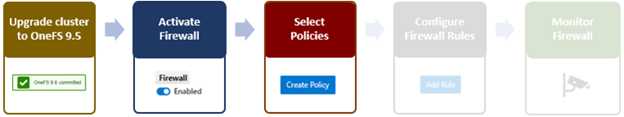
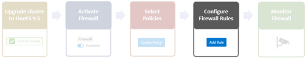
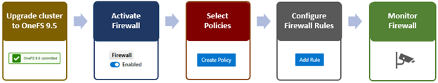
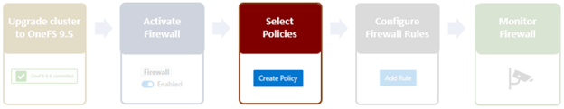
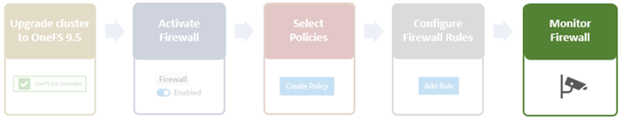
In the final article in this series, we’ll focus on step five of the OneFS firewall provisioning process and turn our attention to some of the management and monitoring considerations and troubleshooting tools associated with the firewall.
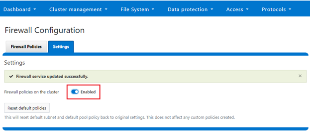
Management and monitoring of the firewall in OneFS 9.5 can be performed via the CLI, or platform API, or WebUI. Since data security threats come from inside an environment as well as out, such as from a rogue IT employee, a good practice is to constrain the use of all-powerful ‘root’, ‘administrator’, and ‘sudo’ accounts as much as possible. Instead of granting cluster admins full rights, a preferred approach is to use OneFS’ comprehensive authentication, authorization, and accounting framework.
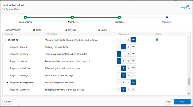
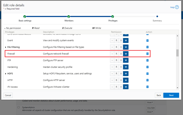
OneFS role-based access control (RBAC) can be used to explicitly limit who has access to configure and monitor the firewall. A cluster security administrator selects the desired multi-tenant access zone, creates a zone-aware role within it, assigns privileges, and then assigns members. For example, from the WebUI under Access > Membership and roles > Roles:
When these members login to the cluster via a configuration interface (WebUI, Platform API, or CLI) they inherit their assigned privileges.
Accessing the firewall from the WebUI and CLI in OneFS 9.5 requires the new ISI_PRIV_FIREWALL administration privilege.
# isi auth privileges -v | grep -i -A 2 firewall

         ID: ISI_PRIV_FIREWALL

Description: Configure network firewall

       Name: Firewall

   Category: Configuration

 Permission: w
This privilege can be assigned one of four permission levels for a role, including:
| Permission Indicator | Description |
| – | No permission. |
| R | Read-only permission. |
| X | Execute permission. |
| W | Write permission. |
By default, the built-in ‘SystemAdmin’ roles is granted write privileges to administer the firewall, while the built-in ‘AuditAdmin’ role has read permission to view the firewall configuration and logs.
With OneFS RBAC, an enhanced security approach for a site could be to create two additional roles on a cluster, each with an increasing realm of trust. For example:
- An IT ops/helpdesk role with ‘read’ access to the snapshot attributes would permit monitoring and troubleshooting the firewall, but no changes:
| RBAC Role | Firewall Privilege | Permission |
| IT_Ops | ISI_PRIV_FIREWALL | Read |
For example:
# isi auth roles create IT_Ops

# isi auth roles modify IT_Ops --add-priv-read ISI_PRIV_FIREWALL

# isi auth roles view IT_Ops | grep -A2 -i firewall

             ID: ISI_PRIV_FIREWALL

     Permission: r
2. A Firewall Admin role would provide full firewall configuration and management rights:
| RBAC Role | Firewall Privilege | Permission |
| FirewallAdmin | ISI_PRIV_FIREWALL | Write |
For example:
# isi auth roles create FirewallAdmin
# isi auth roles modify FirewallAdmin –add-priv-write ISI_PRIV_FIREWALL
# isi auth roles view FirewallAdmin | grep -A2 -i firewall
ID: ISI_PRIV_FIREWALL
Permission: w
Note that when configuring OneFS RBAC, remember to remove the ‘ISI_PRIV_AUTH’ and ‘ISI_PRIV_ROLE’ privilege from all but the most trusted administrators.
Additionally, enterprise security management tools such as CyberArk can also be incorporated to manage authentication and access control holistically across an environment. These can be configured to frequently change passwords on trusted accounts (ie. every hour or so), require multi-Level approvals prior to retrieving passwords, as well as track and audit password requests and trends.
OneFS Firewall Limits
When working with the OneFS Firewall, there are some upper bounds to the configurable attributes to keep in mind. These include:
| Name | Value | Description |
| MAX_INTERFACES | 500 | Maximum number of L2 interfaces including Ethernet, VLAN, LAGG interfaces on a node. |
| MAX _SUBNETS | 100 | Maximum number of subnets within a OneFS cluster |
| MAX_POOLS | 100 | Maximum number of network pools within a OneFS cluster |
| DEFAULT_MAX_RULES | 100 | Default value of maximum rules within a firewall policy |
| MAX_RULES | 200 | Upper limit of maximum rules within a firewall policy |
| MAX_ACTIVE_RULES | 5000 | Upper limit of total active rules across the whole cluster |
| MAX_INACTIVE_POLICIES | 200 | Maximum number of policies which are not applied to any network subnet or pool. They will not be written into ipfw table. |
Firewall performance
Be aware that, while the OneFS firewall can greatly enhance the network security of a cluster, by nature of its packet inspection and filtering activity, it does come with a slight performance penalty (generally less than 5%).
Firewall and hardening mode
If OneFS STIG Hardening (ie. via ‘isi hardening apply’) is applied to a cluster with the OneFS Firewall disabled, the firewall will be automatically activated. On the other hand, if the firewall is already enabled, then there will be no change and it will remain active.
Firewall and user-configurable ports
Some OneFS services allow the TCP/UDP ports on which the daemon listens to be changed. These include:
| Service | CLI Command | Default Port |
| NDMP | isi ndmp settings global modify –port | 10000 |
| S3 | isi s3 settings global modify –https-port | 9020, 9021 |
| SSH | isi ssh settings modify –port | 22 |
The default ports for these services are already configured in the associated global policy rules. For example, for the S3 protocol:
# isi network firewall rules list | grep s3

default_pools_policy.rule_s3                  55     Firewall rule on s3 service                                                             allow

# isi network firewall rules view default_pools_policy.rule_s3

          ID: default_pools_policy.rule_s3

        Name: rule_s3

       Index: 55

 Description: Firewall rule on s3 service

    Protocol: TCP

   Dst Ports: 9020, 9021

Src Networks: -

   Src Ports: -

      Action: allow
Note that the global policies, or any custom policies, do not auto-update if these ports are reconfigured. This means that the firewall policies must be manually updated when changing ports. For example, if the NDMP port is changed from 10000 to 10001:
# isi ndmp settings global view

                       Service: False

                          Port: 10000

                           DMA: generic

          Bre Max Num Contexts: 64

MSB Context Retention Duration: 300

MSR Context Retention Duration: 600

        Stub File Open Timeout: 15

             Enable Redirector: False

              Enable Throttler: False

       Throttler CPU Threshold: 50

# isi ndmp settings global modify --port 10001

# isi ndmp settings global view | grep -i port

                          Port: 10001
The firewall’s NDMP rule port configuration must also be reset to 10001:
# isi network firewall rule list | grep ndmp

default_pools_policy.rule_ndmp                44     Firewall rule on ndmp service                                                           allow

# isi network firewall rule modify default_pools_policy.rule_ndmp --dst-ports 10001 --live

# isi network firewall rule view default_pools_policy.rule_ndmp | grep -i dst

   Dst Ports: 10001
Note that the ‘–live’ flag is specified to enact this port change immediately.
Firewall and source-based routing
Under the hood, OneFS source-based routing (SBR) and the OneFS Firewall both leverage ‘ipfw’. As such, SBR and the firewall share the single ipfw table in the kernel. However, the two features use separate ipfw table partitions.
This allows SBR and the firewall to be activated independently of each other. For example, even if the firewall is disabled, SBR can still be enabled and any configured SBR rules displayed as expected (ie. via ‘ipfw set 0 show’).
Firewall and IPv6
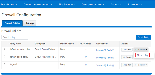
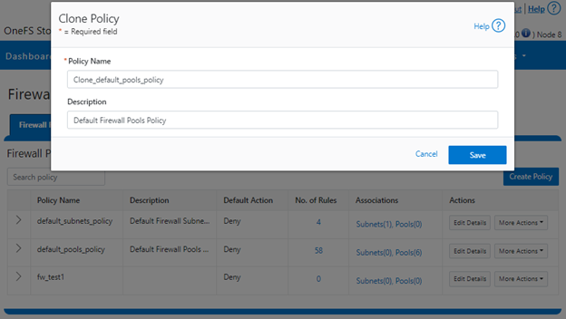
Note that the firewall’s global default policies have a rule allowing ICMP6 by default. For IPv6 enabled networks, ICMP6 is critical for the functioning of NDP (Neighbor Discovery Protocol). As such, when creating custom firewall policies and rules for IPv6-enabled network subnets/pools, be sure to add a rule allowing ICMP6 to support NDP. As discussed in a previous article, an alternative (and potentially easier) approach is to clone a global policy to a new one and just customize its ruleset instead.
Firewall and FTP
The OneFS FTP service can work in two modes: Active and Passive. Passive mode is the default, where FTP data connections are created on top of random ephemeral ports. However, since the OneFS firewall requires fixed ports to operate, it only supports the FTP service in active mode. Attempts to enable the firewall with FTP running in passive mode will generate the following warning:
# isi ftp settings view | grep -i active

          Active Mode: No

# isi network firewall settings modify --enabled yes

FTP service is running in Passive mode. Enabling network firewall will lead to FTP clients having their connections blocked. To avoid this, please enable FTP active mode and ensure clients are configured in active mode before retrying. Are you sure you want to proceed and enable network firewall? (yes/[no]):
In order to activate the OneFS firewall in conjunction with the FTP service, first ensure the FTP service is running in active mode before enabling the firewall. For example:
# isi ftp settings view | grep -i enable

  FTP Service Enabled: Yes

# isi ftp settings view | grep -i active

          Active Mode: No

# isi ftp setting modify –active-mode true

# isi ftp settings view | grep -i active

          Active Mode: Yes

# isi network firewall settings modify --enabled yes
Note: Verify FTP active mode support and/or firewall settings on the client side, too.
Firewall monitoring and troubleshooting
When it comes to monitoring the OneFS firewall, the following logfiles and utilities provide a variety of information and are a good source to start investigating an issue:
| Utility | Description |
| /var/log/isi_firewall_d.log | Main OneFS firewall log file, which includes information from firewall daemon. |
| /var/log/isi_papi_d.log | Logfile for platform AP, including Firewall related handlers. |
| isi_gconfig -t firewall | CLI command that displays all firewall configuration info. |
| ipfw show | CLI command which displays the ipfw table residing in the FreeBSD kernel. |
Note that the above files and command output are automatically included in logsets generated by the ‘isi_gather_info’ data collection tool.
The isi_gconfig command can be run with the ‘-q’ flag to identify any values that are not at their default settings. For example, the stock (default) isi_firewall_d gconfig context will not report any configuration entries:
# isi_gconfig -q -t firewall

[root] {version:1}
The firewall can also be run in the foreground for additional active rule reporting and debug output. For example, first shut down the isi_firewall_d service:
# isi services -a isi_firewall_d disable

The service 'isi_firewall_d' has been disabled.
Next, start up the firewall with the ‘-f’ flag.
# isi_firewall_d -f

Acquiring kevents for flxconfig

Acquiring kevents for nodeinfo

Acquiring kevents for firewall config

Initialize the firewall library

Initialize the ipfw set

ipfw: Rule added by ipfw is for temporary use and will be auto flushed soon. Use isi firewall instead.

cmd:/sbin/ipfw set enable 0 normal termination, exit code:0

isi_firewall_d is now running

Loaded master FlexNet config (rev:312)

Update the local firewall with changed files: flx_config, Node info, Firewall config

Start to update the firewall rule...

flx_config version changed!                             latest_flx_config_revision: new:312, orig:0

node_info version changed!                              latest_node_info_revision: new:1, orig:0

firewall gconfig version changed!                               latest_fw_gconfig_revision: new:17, orig:0

Start to update the firewall rule for firewall configuration (gconfig)

Start to handle the firewall configure (gconfig)

Handle the firewall policy default_pools_policy

ipfw: Rule added by ipfw is for temporary use and will be auto flushed soon. Use isi firewall instead.

32043 allow tcp from any to any 10000 in

cmd:/sbin/ipfw add 32043 set 8 allow TCP from any  to any 10000 in  normal termination, exit code:0

ipfw: Rule added by ipfw is for temporary use and will be auto flushed soon. Use isi firewall instead.

32044 allow tcp from any to any 389,636 in

cmd:/sbin/ipfw add 32044 set 8 allow TCP from any  to any 389,636 in  normal termination, exit code:0

Snip...
If the OneFS firewall is enabled and some network traffic is blocked, either this or the ‘ipfw show’ CLI command will often provide the first clues.
Please note that the ‘ipfw’ command should NEVER be used to modify the OneFS firewall table!
For example, say a rule is added to the default pools policy denying traffic on port 9876 from all source networks (0.0.0.0/0):
# isi network firewall rules create default_pools_policy.rule_9876 --index=100 --dst-ports 9876 --src-networks 0.0.0.0/0 --action deny –live

# isi network firewall rules view default_pools_policy.rule_9876

          ID: default_pools_policy.rule_9876

        Name: rule_9876

       Index: 100

 Description:

    Protocol: ALL

   Dst Ports: 9876

Src Networks: 0.0.0.0/0

   Src Ports: -

      Action: deny
Running ‘ipfw show’ and grepping for the port will show this new rule:
# ipfw show | grep 9876

32099            0               0 deny ip from any to any 9876 in
The ‘ipfw show’ command output also reports the statistics of how many IP packets have matched each rule This can be incredibly useful when investigating firewall issues. For example, a telnet session is initiated to the cluster on port 9876 from a client:
# telnet 10.224.127.8 9876

Trying 10.224.127.8...

telnet: connect to address 10.224.127.8: Operation timed out

telnet: Unable to connect to remote host
The connection attempt will time out since the port 9876 ‘deny’ rule will silently drop the packets. At the same time, the ‘ipfw show’ command will increment its counter to report on the denied packets. For example:
# ipfw show | grep 9876

32099            9             540 deny ip from any to any 9876 in
If this behavior is not anticipated or desired, the rule name can be found searching the rules list for the port number, in this case port 9876:
# isi network firewall rules list | grep 9876

default_pools_policy.rule_9876                100                                                                deny
The offending rule can then be reverted to ‘allow’ traffic on port 9876:
# isi network firewall rules modify default_pools_policy.rule_9876 --action allow --live
Or easily deleted, if preferred:
# isi network firewall rules delete default_pools_policy.rule_9876 --live

Are you sure you want to delete firewall rule default_pools_policy.rule_9876? (yes/[no]): yes