OneFS and Cluster Quorum

Received a couple of recent enquires about the role and effects of cluster quorum in OneFS. So thought it might be useful to revisit this, and associated concepts, in an article.

The premise was this:

A 3 node cluster at +2d:1n or +1n protection can run fine in a degraded mode with only two active nodes and one failed node:

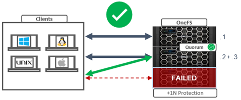
Given the above, shouldn’t a 4 node cluster at +2n also be able to sustain a two node failure and run fine in degraded state with two active nodes?

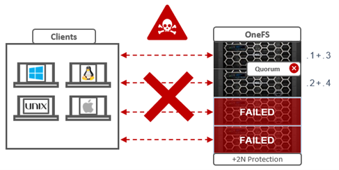
Spoiler alert: The answer is no, and the reason is the OneFS cluster quorum requirement.

So what’s going on here?

In order for a cluster to properly function and accept data writes, a quorum of nodes must be active and responding. A quorum is defined as a simple majority: a cluster with N nodes must have ⌊N/2⌋+1 nodes online in order to allow writes. For example, in a seven-node cluster, four nodes would be required for a quorum. If a node or group of nodes is up and responsive, but is not a member of a quorum, it runs in a read-only state.

OneFS uses a quorum to prevent ‘split-brain’ conditions that can be introduced if the cluster should temporarily divide into two clusters. By following the quorum rule, the architecture guarantees that regardless of how many nodes fail or come back online, if a write takes place, it can be made consistent with any previous writes that have ever taken place. The quorum also dictates the number of nodes required in order to move to a given data protection level. For an erasure-code-based protection-level of 𝑁+𝑀, the cluster must contain at least 2𝑀+1 nodes. For example, a minimum of five nodes is required for a +2n configuration:

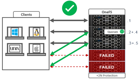
This allows for a simultaneous loss of two nodes while still maintaining a quorum of three nodes for the cluster to remain fully operational.

If a cluster does drop below quorum, the file system will automatically be placed into a protected, read-only state, denying writes, but still allowing read access to the available data.

Within OneFS, quorum is a property of the group management protocol (GMP) group which helps enforce consistency across node disconnects. It is very similar to the common definition of quorum in distributed systems. It can be shown that requiring ⌊𝑁/2⌋+ 1 replicas to be available can guarantee that no updates are lost. Quorum performs this specific purpose within OneFS.

Since both nodes and drives in OneFS may be readable, but not writable, OneFS actually has two quorum properties:

Type Description
Read quorum Read quorum is defined as having ⌊𝑁/2⌋ + 1 nodes readable.
Write quorum Write quorum is defined as having at least ⌊𝑁/2⌋ + 1 nodes writable.

Under the hood, OneFS read quorum is represented by the sysctl ‘efs.gmp.has_quorum’, and write quorum by  ‘efs.gmp.has_super_block_quorum’. For example:

# sysctl efs.gmp.has_quorum

efs.gmp.has_quorum: 1

# sysctl efs.gmp.has_super_block_quorum

efs.gmp.has_super_block_quorum: 1

In the above example, the value of ‘1’ for each confirms that the cluster currently has both read and write quorum respectively.

Note that any nodes that are not in a cluster’s main quorum group form multiple groups. A group of nodes with quorum is referred to as the ‘majority side’. Similarly, any node group without quorum is termed a ‘minority side’. By definition, there can only be one majority group, but there may be multiple minority groups. A group which has one or more components in a failed state is called ‘degraded’. The degraded property is frequently used as an optimization to avoid checking the capabilities of each component. The term ‘degraded’ is also used to refer to components without their maximum capabilities.

For example, consider the earlier 4-node cluster example with a protection level of +2n and two nodes down. Even though the protection level can theoretically sustain two node failures, the minimum cluster size has been violated, hence the cluster cannot write due to lack of quorum. The following table lists various OneFS protection levels and their associated minimum cluster or pool sizes and quorum counts:

FEC Protection level Failure Tolerance Minimum Cluster/Pool Size Minimum Quorum Size
+1 Tolerate failure of 1 drive OR 1 node 3 nodes 2 nodes
+2 Tolerate failure of 2 drives OR 2 nodes 5 nodes 3 nodes
+3 Tolerate failure of 3 drives or 3 nodes 7 nodes 4 nodes
+4 Tolerate failure of 4 nodes 9 nodes 5 nodes

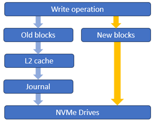
The OneFS Job Engine also includes a process called Collect, which acts as an orphaned block collector. If a cluster splits during a write operation, some blocks that were allocated for the file may need to be re-allocated on the quorum side. This will ‘orphan’ allocated blocks on the non-quorum side. When the cluster re-merges, the job engine’s Collect job locates these orphaned blocks through a parallelized mark-and-sweep scan and reclaims them as free space for the cluster.

File system operations typically query a GMP group several times before completing. A group may change over the course of an operation, but the operation needs a consistent view. This is provided by the group info, which is the primary interface modules use to query group state.

The efs.gmp.group sysctl can be queried to determine the current group state of a cluster. For example:

# sysctl efs.gmp.group

efs.gmp.group: <8f8f4b> (92) :{ 1-14:0-14, 15:0-13, 16-19:0-14, 20:0-13, 21-33:0-14, 34:0-4,6-10,12-14, 35-36:0-14, 37-48:0-19, 49-60:0-14, 61-62:0-13, 63-81:0-14, 82:0-7,9-14, 83-87:0-14, 88:0-13, 89-91:0-14, 92:0-1,3-14, smb: 1-92, nfs: 1-92, swift: 1-92, all_enabled_protocols: 1-92, isi_cbind_d: 1-92, lsass: 1-92, s3: 1-92, external_connectivity: 1-92 }

As shown in this large cluster example above, the output includes the GMP’s group state, but also information about services provided by nodes in the cluster. This allows nodes in the cluster to discover when services change state on other nodes and take the appropriate action when this happens. An example is SMB lock expiry, which uses GMP service information to clean up locks held by other nodes when the service owning the lock goes down.

Additional detailed current GMP state information can be gleaned from the output of the following sysctl:

# sysctl efs.gmp.current_info

Processes change the service state in GMP by opening and closing service devices. A particular service will transition from down to up in the GMP group when it opens the file descriptor for a device. Closing the service file descriptor will trigger a group change that reports the service as down. A process can explicitly close the file descriptor if it chooses, but most often the file descriptor will remain open for the duration of the process and closed automatically by the kernel when it terminates.

OneFS depends on a consistent view of a cluster’s group state. For example, in addition to read and write quorum, other decisions, such as choosing lock coordinators, are made assuming all nodes have the same coherent notion of the cluster.

As such, an understanding of OneFS quorum, groups, and their related group change messages allows you to determine the current health of a cluster – as well as reconstruct the cluster’s history when troubleshooting issues that involve cluster stability, network health, and data integrity.

Group changes originate from multiple sources, depending on the particular state. Drive group changes are initiated by the drv module. Service group changes are initiated by processes opening and closing service devices. Each group change creates a new group ID, comprising a node ID and a group serial number. This group ID can be used to quickly determine whether a cluster’s group has changed, and is invaluable for troubleshooting cluster issues, by identifying the history of group changes across the nodes’ log files.

GMP provides coherent cluster state transitions using a process similar to two-phase commit, with the up and down states for nodes being directly managed by the GMP. The Remote Block Manager (RBM)  provides the communication channel that connect devices in the OneFS. When a node mounts /ifs it initializes the RBM in order to connect to the other nodes in the cluster, and uses it to exchange GMP Info, negotiate locks, and access data on the other nodes.

Before /ifs is mounted, a ‘cluster’ is just a list of MAC and IP addresses in array.xml, managed by ibootd when nodes join or leave the cluster. When mount_efs is called, it must first determine what it‘s contributing to the file system, based on the information in drives.xml. After a cluster (re)boot, the first node to mount /ifs is immediately placed into a group on its own, with all other nodes marked down. As the Remote Block Manager (RBM) forms connections, the GMP merges the connected nodes, enlarging the group until the full cluster is represented. Group transactions where nodes transition to UP are called a ‘merge’, whereas a node transitioning to down is called a split.

OneFS Software-Defined Persistent Memory Journal

Unlike previous platforms which used NVDIMMs, the F710 and F210 nodes see a change to the system journal, instead using a 32GB Software Defined Persistent Memory (SDPM) solution to provide persistent storage for the OneFS journal. This change also has the benefit of freeing up a DIMM slot, unlike the NVDIMM on previous platforms.

But before we get into the details, first, a quick refresher on the OneFS journal.

A primary challenge for any storage system is providing performance and ACID (atomicity, consistency, isolation, and durability) guarantees using commodity drives. Drives only support the atomicity of a single sector write, yet complex file system operations frequently update several blocks in a single transaction. For example, a rename operation must modify both the source and target directory blocks. If the system crashes or loses power during an operation that updates multiple blocks, the file system will be inconsistent if some updates are visible and some are not.

The journal is among the most critical components of a PowerScale node. When the OneFS writes to a drive, the data goes straight to the journal, allowing for a fast reply.

OneFS uses journalling to ensure consistency across both disks locally within a node and disks across nodes.

Block writes go to the journal first, and a transaction must be marked as ‘committed’ in the journal before returning success to the file system operation. Once the transaction is committed, the change is guaranteed to be stable. If the node crashes or loses power, the changes can still be applied from the journal at mount time via a ‘replay’ process. The journal uses a battery-backed persistent storage medium, such as NVRAM, in order to be available after a catastrophic node event such as a crash or power loss. It must also be:

Journal Performance Characteristic Description
High throughput All blocks (and therefore all data) go through the journal, so it cannot become a bottleneck.
Low latency Since transaction state changes are often in the latency path multiple times for a single operation, particularly for distributed transactions.

The OneFS journal mostly operates at the physical level, storing changes to physical blocks on the local node. This is necessary because all initiators in OneFS have a physical view of the file system, and therefore issue physical read and write requests to remote nodes. The OneFS journal supports both 512byte and 8KiB block sizes of 512 bytes for storing written inodes and blocks respectively.

By design, the contents of a node’s journal are only needed in a catastrophe, such as when memory state is lost. For fast access during normal operation, the journal is mirrored in RAM. Thus, any reads come from RAM and the physical journal itself is write-only in normal operation. The journal contents are read at mount time for replay. In addition to providing fast stable writes, the journal also improves performance by serving as a write-back cache for disks. When a transaction is committed, the blocks are not immediately written to disk. Instead, it is delayed until the space is needed. This allows the I/O scheduler to perform write optimizations such as reordering and clustering blocks. This also allows some writes to be elided when another write to the same block occurs quickly, or the write is otherwise unnecessary, such as when the block is freed.

So the OneFS journal provides the initial stable storage for all writes and does not release a block until it is guaranteed to be stable on a drive. This process involves multiple steps and spans both the file system and operating system. The high-level flow is as follows:

Step Operation Description
1 Transaction prep A block is written on a transaction, for example a write_block message is received by a node. An asynchronous write is started to the journal. The transaction prepare step will wait until all writes on the transaction complete.
2 Journal delayed write The transaction is committed. Now the journal issues a delayed write. This simply marks the buffer as dirty.
3 Buffer monitoring A daemon monitors the number of dirty buffers and issues the write to the drive upon reach its threshold.
4 Write completion notification The journal receives an upcall indicating that the write is complete.
5 Threshold reached Once journal space runs low or an idle timeout expires, the journal issues a cache flush to the drive to ensure the write is stable.
6 Flush to disk When cache flush completes, all writes completed before the cache flush are known stable. The journal frees the space.

The F710 and F210 see the introduction of Dell’s VOSS M.2 SSD drive as the non-volatile device for the SDPM journal vault.  The SDPM itself comprises two main elements:

Component Description
BBU The BBU pack (battery backup unit) supplies temporary power to the CPUs and memory allowing them to perform a backup in the event of a power loss.
Vault A 32GB M.2 NVMe to which the system memory is vaulted.

While the BBU is self-contained, the M.2 NVMe vault is housed within a VOSS module, and both components are easily replaced if necessary.

The following CLI command confirms the 32GB size of the SDPM journal in the F710 and F210 nodes:

# grep -r supported_size /etc/psi/psf

/etc/psi/psf/MODEL_F210/journal/JOURNAL_SDPM/journal-1.0-psi.conf:             supported_size = 34359738368;

/etc/psi/psf/MODEL_F710/journal/JOURNAL_SDPM/journal-1.0-psi.conf:             supported_size = 34359738368;

/etc/psi/psf/journal/JOURNAL_NVDIMM_1x16GB/journal-1.0-psi.conf:               supported_size = 17179869184;

The basic SDPM operation is illustrated in the diagram below:

Essentially, the node’s memory state, including any uncommitted writes, etc, in the DDR5 RDIMMS that are being protected, come up through the memory controller, through the CPU and caching hierarchy, and are then vaulted to the non-volatile M.2 within the VOSS module.

The VOSS M.2 module itself is comprised of the following parts:

In the event of a failure, this entire carrier assembly is replaced, rather than just the M.2 itself.

Note that with the new VOSS, M.2 firmware upgrades are now managed by iDRAC using DUP, rather than by OneFS and the DSP as in prior PowerScale platforms.

Both the BBU and VOSS module are located at the front of the chassis, and are connected to the motherboard and power source as depicted by the red and blue lines in the following graphic:

Additionally, with OneFS 9.7, given the low latency IO characteristics of the drives, the PowerScale NVMe-based all-flash nodes also now have a write operation fast path direct to SSD for newly allocated blocks as shown below:

This is a major performance boost, particularly for streaming write workloads, and we’ll explore this more closely in a future article.

PowerScale F710 Platform Node

In this article, we’ll turn our focus to the new PowerScale F710 hardware node that was launched a couple of weeks back. Here’s where this new platform lives in the current hardware hierarchy:

The PowerScale F710 is a high-end all-flash platform that utilizes a dual-socket 4th gen Zeon processor with 512GB of memory and ten NVMe drives, all contained within a 1RU chassis. Thus, the F710 offers a substantial hardware evolution from previous generations, while also focusing on environmental sustainability, reducing power consumption and carbon footprint, while delivering blistering performance. This makes the F710 and ideal candidate for demanding workloads such as M&E content creation and rendering, high concurrency and low latency workloads such as chip design (EDA), high frequency trading, and all phases of generative AI workflows, etc.

An F710 cluster can comprise between 3 and 252 nodes. Inline data reduction, which incorporates compression, dedupe, and single instancing, is also included as standard to further increase the effective capacity.

The F710 is based on the 1U R660 PowerEdge server platform, with dual socket Intel Sapphire Rapids CPUs. Front-End networking options include 10/25 GbE and with 100 GbE for the Back-End network. As such, the F710’s core hardware specifications are as follows:

Attribute F710 Spec
Chassis 1RU Dell PowerEdge R660
CPU Dual socket, 24 core Intel Sapphire Rapids 6442Y @2.6GHz
Memory 512GB Dual rank DDR5 RDIMMS (16 x 32GB)
Journal 1 x 32GB SDPM
Front-end network 2 x 100GbE or 25GbE
Back-end network 2 x 100GbE
NVMe SSD drives 10

These node hardware attributes can be easily viewed from the OneFS CLI via the ‘isi_hw_status’ command. Also note that, at the current time, the F710 is only available in a 512GB memory configuration.

Starting at the business end of the node, the front panel allows the user to join an F710 to a cluster and displays the node’s name once it has successfully joined.

Removing the top cover, the internal layout of the F710 chassis is as follows:

The Dell ‘Smart Flow’ chassis is specifically designed for balanced airflow, and enhanced cooling is primarily driven by four dual-fan modules. Additionally, the redundant power supplies also contain their own air flow apparatus and can be easily replaced from the rear without opening the chassis.

For storage, each PowerScale F710 node contains ten NVMe SSDs, which are currently available in the following capacities and drive styles:

Standard drive capacity SED-FIPS drive capacity SED-non-FIPS drive capacity
3.84 TB TLC 3.84 TB TLC
7.68 TB TLC 7.68 TB TLC
15.36 TB QLC Future availability 15.36 TB QLC
30.72 TB QLC Future availability 30.72 TB QLC

Note that 15.36TB and 30.72TB SED-FIPS drive options are planned for future release.

Drive subsystem-wise, the PowerScale F710 1RU chassis is fully populated with ten NVMe SSDs. These are housed in drive bays spread across the front of the node as follows:

This is in contrast to, and provides improved density over its predecessor, the F600, which contains eight NVMe drives per node.

The NVMe drive connectivity is across PCIe lanes, and these drives use the NVMe and NVD drivers. The NVD is a block device driver that exposes an NVMe namespace like a drive and is what most OneFS operations act upon, and each NVMe drive has a /dev/nvmeX, /dev/nvmeXnsX and /dev/nvdX device entry  and the locations are displayed as ‘bays’. Details can be queried with OneFS CLI drive utilities such as ‘isi_radish’ and ‘isi_drivenum’. For example:

# isi_drivenum

Bay  0   Unit 15     Lnum 9     Active      SN:S61DNE0N702037   /dev/nvd5

Bay  1   Unit 14     Lnum 10    Active      SN:S61DNE0N702480   /dev/nvd4

Bay  2   Unit 13     Lnum 11    Active      SN:S61DNE0N702474   /dev/nvd3

Bay  3   Unit 12     Lnum 12    Active      SN:S61DNE0N702485   /dev/nvd2

Bay  4   Unit 19     Lnum 5     Active      SN:S61DNE0N702031   /dev/nvd9

Bay  5   Unit 18     Lnum 6     Active      SN:S61DNE0N702663   /dev/nvd8

Bay  6   Unit 17     Lnum 7     Active      SN:S61DNE0N702726   /dev/nvd7

Bay  7   Unit 16     Lnum 8     Active      SN:S61DNE0N702725   /dev/nvd6

Bay  8   Unit 23     Lnum 1     Active      SN:S61DNE0N702718   /dev/nvd1

Bay  9   Unit 22     Lnum 2     Active      SN:S61DNE0N702727   /dev/nvd10

Moving to the back of the chassis, the rear of the F710 contains the power supplies, network, and management interfaces, which are arranged as follows:

The F710 nodes are available in the following networking configurations, with a 25/100Gb ethernet front-end and 100Gb ethernet back-end:

Front-end NIC Back-end NIC F710 NIC Support
100GbE 100GbE Yes
100GbE 25GbE No
25GbE 100GbE Yes
25GbE 25GbE No

Note that, like the F210, an Infiniband backend is not supported on the F710 at the current time.

Compared with its F600 predecessor, the F710 sees a number of hardware performance upgrades. These include a move to PCI Gen5, Gen 4 NVMe, DDR5 memory, Sapphire Rapids CPU, and a new software-defined persistent memory file system journal ((SPDM). Also the 1GbE management port has moved to Lan-On-Motherboard (LOM), whereas the DB9 serial port is now on a RIO card. Firmware-wise, the F710 and OneFS 9.7 require a minimum of NFP 12.0.

In terms of performance, the new F710 provides a considerable leg up on both the previous generation F600 and F600 prime. This is particularly apparent with NFSv3 streaming reads, as can be seen below:

Given its additional drives (ten SSDs versus eight for the F600s) plus this performance disparity, the F710 does not currently have any other compatible node types. This means that, unlike the F210, the minimum F710 configuration requires the addition of a three node pool.

PowerScale F210 Platform Node

In this article, we’ll take a quick peek at the new PowerScale F210 hardware platform that was released last week. Here’s where this new node sits in the current hardware hierarchy:

The PowerScale F210 is an entry level, performant, all-flash platform that utilizes NVMe SSDs and a single-socket CPU 1U PowerEdge platform with 128GB of memory per node.  The ideal use cases for the F210 include high performance workflows, such as M&E, EDA, AI/ML, and other HPC applications.

An F210 cluster can comprise between 3 and 252 nodes, each of which contains four 2.5” drive bays populated with a choice of 1.92TB, 3.84TB, 7,68TB TLC, or 15.36TB QLC enterprise NVMe SSDs. Inline data reduction, which incorporates compression, dedupe, and single instancing, is also included as standard and enabled by default to further increase the effective capacity.

The F210 is based on the 1U R660 PowerEdge server platform, with a single socket Intel Sapphire Rapids CPU.

The node’s front panel has limited functionality compared to older platform generations and simply allows the user to join a node to a cluster and display the node name once the node has successfully joined.

An F210 node’s serial number can be found either by viewing /etc/isilon_serial_number or via the following CLI command syntax. For example:

# isi_hw_status | grep SerNo
  SerNo: HVR3FZ3

The serial number reported by OneFS will match that of the service tag attached to the physical hardware and the /etc/isilon_system_config file will report the appropriate node type. For example:

# cat /etc/isilon_system_config
PowerScale F210

Under the hood, the F210’s core hardware specifications are as follows:

Attribute F210 Spec
Chassis 1RU Dell PowerEdge R660
CPU Single socket, 12 core Intel Sapphire Rapids 4410Y @2GHz
Memory 128GB Dual rank DDR5 RDIMMS (8 x 16GB)
Journal 1 x 32GB SDPM
Front-end network 2 x 100GbE or 25GbE
Back-end network 2 x 100GbE or 25GbE
NVMe SSD drives 4

The node hardware attributes can be gleaned from OneFS by running the ‘isi_hw_status’ CLI command. For example:

f2101-1# isi_hw_status -c

  HWGen: PSI

Chassis: POWEREDGE (Dell PowerEdge)

    CPU: GenuineIntel (2.00GHz, stepping 0x000806f8)

   PROC: Single-proc, 12-HT-core

    RAM: 102488403968 Bytes

   Mobo: 0MK29P (PowerScale F210)

  NVRam: NVDIMM (NVDIMM) (8192MB card) (size 8589934592B)

 DskCtl: NONE (No disk controller) (0 ports)

 DskExp: None (No disk expander)

PwrSupl: PS1 (type=AC, fw=00.1B.53)

PwrSupl: PS2 (type=AC, fw=00.1B.53)

While the actual health of the CPU and power supplies can be quickly verified as follows:

# isi_hw_status -s

Power Supplies OK

Power Supply PS1 good

Power Supply PS2 good

CPU Operation (raw 0x881B0000)  = Normal

Additionally, the ‘-A’ flag (All) can also be used with ‘isi_hw-status’ to query a plethora of hardware and environmental information.

Node and drive firmware versions can also be checked with the ‘isi_firmware_tool’ utility. For example:

f2101-1# isi_firmware_tool --check

Ok

f2101-1# isi_firmware_tool --show

Thu Oct 26 11:42:32 2023 - Drive_Support_v1.46.tgz

Thu Oct 26 11:42:58 2023 - IsiFw_Package_v11.7qa1.tar

The internal layout of the F210 chassis with the risers removed is as follows:

The cooling is primarily driven by four dual-fan modules, which can be easily accessed and replaced as follows:

Additionally, the power supplies also contain their own air flow apparatus, and can be easily replaced from the rear without opening the chassis.

For storage, each PowerScale F210 node contains four NVMe SSDs, which are currently available in the following capacities and drive styles:

Standard drive capacity SED-FIPS drive capacity SED-non-FIPS drive capacity
1.92 TB TLC 1.92 TB TLC

3.84 TB TLC 3.84 TB TLC

7.68 TB TLC 7.68 TB TLC

15.36 TB QLC Future availability 15.36 TB QLC

Note that a 15.36TB SED-FIPS drive option is planned for future release. Additionally, the 1.92TB drives in the F210 can also be short-stroke formatted for node compatibility with F200s containing 960GB SSD drives. More on this later in the article.

The F210’s NVMe SSDs populate the drive bays on the left front of the chassis, as illustrated in the following front view (with bezel removed):

Drive subsystem-wise, OneFS provides NVMe support across PCIe lanes, and the SSDs use the NVMe and NVD drivers. The NVD is a block device driver that exposes an NVMe namespace like a drive and is what most OneFS operations act upon, and each NVMe drive has a /dev/nvmeX, /dev/nvmeXnsX and /dev/nvdX device entry  and the locations are displayed as ‘bays’. Details can be queried with OneFS CLI drive utilities such as ‘isi_radish’ and ‘isi_drivenum’. For example:

f2101-1# isi_drivenum
Bay 0   Unit 3      Lnum 0     Active      SN:BTAC2263000M15PHGN   /dev/nvd3
Bay 1   Unit 2      Lnum 2     Active      SN:BTAC226206VB15PHGN   /dev/nvd2
Bay 2   Unit 0      Lnum 1     Active      SN:BTAC226206R515PHGN   /dev/nvd0
Bay 3   Unit 1      Lnum 3     Active      SN:BTAC226207ER15PHGN   /dev/nvd1
Bay 4   Unit N/A    Lnum N/A   N/A         SN:N/A              N/A
Bay 5   Unit N/A    Lnum N/A   N/A         SN:N/A              N/A
Bay 6   Unit N/A    Lnum N/A   N/A         SN:N/A              N/A
Bay 7   Unit N/A    Lnum N/A   N/A         SN:N/A              N/A
Bay 8   Unit N/A    Lnum N/A   N/A         SN:N/A              N/A
Bay 9   Unit N/A    Lnum N/A   N/A         SN:N/A              N/A

As shown, the four NVMe drives occupy bays 0-3, with the remaining six bays unoccupied. These four drives and their corresponding PCI bus addresses can also be viewed via the following CLI command:

f2101-1# pciconf -l | grep nvme
nvme0@pci0:155:0:0:     class=0x010802 card=0x219c1028 chip=0x0b608086 rev=0x00 hdr=0x00
nvme1@pci0:156:0:0:     class=0x010802 card=0x219c1028 chip=0x0b608086 rev=0x00 hdr=0x00
nvme2@pci0:157:0:0:     class=0x010802 card=0x219c1028 chip=0x0b608086 rev=0x00 hdr=0x00
nvme3@pci0:158:0:0:     class=0x010802 card=0x219c1028 chip=0x0b608086 rev=0x00 hdr=0x00

Comprehensive details and telemetry for individual drive are available via the ‘isi_radish’ CLI command using their /dev/nvdX device entry. For example, for /dev/nvd0:

f2101-1# isi_radish -a /dev/nvd0
Drive log page ca: Intel Vendor Unique SMART Log
              Key                              Attribute                                         Field                                                 Value
============================== ======================================== 
(5.0) (4.0)=(171) (0.0)              Program Fail Count                 Normalized Value                                        100
(5.0) (4.0)=(171) (0.1)                                                 Raw Value                                               0
(5.0) (4.0)=(172) (0.0)              Erase Fail Count                   Normalized Value                                        100
(5.0) (4.0)=(172) (0.1)                                                 Raw Value                                               0
(5.0) (4.0)=(173) (2.0)              Wear Leveling Count                Normalized Value                                        100
(5.0) (4.0)=(173) (2.1)                                                 Min. Erase Cycle                                        2
(5.0) (4.0)=(173) (2.2)                                                 Max. Erase Cycle                                        14
(5.0) (4.0)=(173) (2.3)                                                Avg. Erase Cycle                                        5
(5.0) (4.0)=(184) (1.0)              End to End Error Detection Count   Raw Value                                               0
(5.0) (4.0)=(234) (3.0)              Thermal Throttle Status            Percentage                                              0
(5.0) (4.0)=(234) (3.1)                                                 Throttling event count                                  0
(5.0) (4.0)=(243) (1.0)              PLL Lock Loss Count                Raw Value                                               0
(5.0) (4.0)=(244) (1.0)              NAND sectors written divided by .. Raw Value                                               3281155
(5.0) (4.0)=(245) (1.0)              Host sectors written divided by .. Raw Value                                               1445498
(5.0) (4.0)=(246) (1.0)              System Area Life Remaining         Raw Value                                               0
Drive log page de: DellEMC Unique Log Page

              Key                              Attribute                                         Field                                                 Value
============================== ======================================== ======================================================= ==================================================
(6.0)                            DellEMC Unique Log Page                Log Page Revision                                       2
(6.1)                                                                   System Aread Percent Used                               0
(6.2)                                                                   Max Temperature Seen                                    48
(6.3)                                                                   Media Total Bytes Written                               110097292328960
(6.4)                                                                   Media Total Bytes Read                                  176548657233920
(6.5)                                                                   Host Total Bytes Read                                   164172138545152
(6.6)                                                                   Host Total Bytes Written                                48502864347136
(6.7)                                                                   NAND Min. Erase Count                                   2
(6.8)                                                                   NAND Avg. Erase Count                                   5
(6.9)                                                                   NAND Max. Erase Count                                   14
(6.10)                                                                  Media EOL PE Cycle Count                                3000
(6.11)                                                                  Device Raw Capacity                                     15872
(6.12)                                                                  Total User Capacity                                     15360
(6.13)                                                                  SSD Endurance                                           4294967295
(6.14)                                                                  Command Timeouts                                        18446744073709551615
(6.15)                                                                  Thermal Throttle Count                                  0
(6.16)                                                                 Thermal Throttle Status                                 0
(6.17)                                                                  Short Term Write Amplification                          192
(6.18)                                                                  Long Term Write Amplification                           226
(6.19)                                                                  Born on Date                                            06212022
(6.20)                                                                  Assert Count                                            0
(6.21)                                                                  Supplier firmware-visible hardware revision             5
(6.22)                                                                  Subsystem Host Read Commands                            340282366920938463463374607431768211455
(6.23)                                                                  Subsystem Busy Time                                     340282366920938463463374607431768211455
(6.24)                                                                  Deallocate Command Counter                              0
(6.25)                                                                  Data Units Deallocated Counter                          165599450
Log Sense data (Bay 2/nvd0 ) --
Supported log pages 0x1 0x2 0x3 0x4 0x5 0x6 0x80 0x81

SMART/Health Information Log
============================
Critical Warning State:         0x00
 Available spare:               0
 Temperature:                   0
 Device reliability:            0
 Read only:                     0
 Volatile memory backup:        0
Temperature:                    307 K, 33.85 C, 92.93 F
Available spare:                100
Available spare threshold:      10
Percentage used:                0
Data units (512,000 byte) read: 320648767
Data units written:             94732208
Host read commands:             3779434531
Host write commands:            1243274334
Controller busy time (minutes): 33
Power cycles:                   93
Power on hours:                 2718
Unsafe shutdowns:               33
Media errors:                   0
No. error info log entries:     0
Warning Temp Composite Time:    0
Error Temp Composite Time:      0
Temperature 1 Transition Count: 0
Temperature 2 Transition Count: 0
Total Time For Temperature 1:   0
Total Time For Temperature 2:   0

SMART status is threshold NOT exceeded (Bay 2/nvd0 )
NAND Write Amplification: 2.269913, (Bay 2/nvd0 )

Error Information Log
=====================
No error entries found
Bay 2/nvd0  is Dell Ent NVMe SED P5316 RI 15.36TB FW:1.2.0 SN:BTAC226206R515PHGN, 30001856512 blks

                Attr                          Value
=================================== =========================
NAND Bytes Written                  3281155
Host Bytes Written                  1445498

Drive Attributes: (Bay 2/nvd0 )

In contrast, the rear of the F710 chassis contains the power supplies, network, and management interfaces, which are laid out as follows:

The F210 nodes are available in the following networking configurations, with a 25/100Gb ethernet back-end and 25/100Gb ethernet front-end:

Front-end NIC Back-end NIC F210 NIC Support
100GbE 100GbE Yes
100GbE 25GbE No
25GbE 100GbE Yes
25GbE 25GbE Yes

Note that there is currently no support for an F210 Infiniband backend in OneFS 9.7.

These NICs and their PCI bus addresses can be determined via the ’pciconf’ CLI command, as follows:

f2101-1# pciconf -l | grep mlx
mlx5_core0@pci0:23:0:0: class=0x020000 card=0x005815b3 chip=0x101d15b3 rev=0x00 hdr=0x00
mlx5_core1@pci0:23:0:1: class=0x020000 card=0x005815b3 chip=0x101d15b3 rev=0x00 hdr=0x00
mlx5_core2@pci0:111:0:0:        class=0x020000 card=0x005815b3 chip=0x101d15b3 rev=0x00 hdr=0x00
mlx5_core3@pci0:111:0:1:        class=0x020000 card=0x005815b3 chip=0x101d15b3 rev=0x00 hdr=0x00

Similarly, the NIC hardware details and drive firmware versions can be view as follows:

f2101-1# mlxfwmanager
Device #1:
----------
  Device Type:      ConnectX6DX
  Part Number:      0F6FXM_08P2T2_Ax
  Description:      Mellanox ConnectX-6 Dx Dual Port 100 GbE QSFP56 Network Adapter
  PSID:             DEL0000000027
  PCI Device Name:  pci0:23:0:0
  Base GUID:        a088c20300052a3c
  Base MAC:         a088c2052a3c
  Versions:         Current        Available
     FW             22.36.1010     N/A
     PXE            3.6.0901       N/A
     UEFI           14.29.0014     N/A
  Status:           No matching image found

Device #2:
----------
  Device Type:      ConnectX6DX
  Part Number:      0F6FXM_08P2T2_Ax
  Description:      Mellanox ConnectX-6 Dx Dual Port 100 GbE QSFP56 Network Adapter
  PSID:             DEL0000000027
  PCI Device Name:  pci0:111:0:0
  Base GUID:        a088c2030005194c
  Base MAC:         a088c205194c
  Versions:         Current        Available
     FW             22.36.1010     N/A
     PXE            3.6.0901       N/A
     UEFI           14.29.0014     N/A
  Status:           No matching image found

Performance-wise, the new F210 is a relative powerhouse compared to the F200. This is especially true for NFSv3 streaming reads, as can be seen below:

OneFS node compatibility provides the ability to have similar node types and generations within the same node pool. In OneFS 9.7, compatibility between the F210 nodes and the previous generation F200 platform is supported.

Component F200 F210
Platform R640 R660
Drives 4 x SAS SSD 4 x NVMe SSD
CPU Intel Xeon Silver 4210 (Cascade Lake) Intel Xeon Silver 4410Y (Sapphire Rapids)
Memory 96GB DDR4 96GB DDR5

This compatibility facilitates the addition of individual F210 nodes to an existing node pool comprising three of more F200s if desired, rather creating a F210 new node pool. Despite the different drive subsystem across the two platforms, and the performance profiles above. Because of this, however, the F210/F200 node compatibility is slightly more nuanced, and the F210 NVMe SSDs are considered ‘soft restriction’ compatible with the F200 SAS SSDs. Additionally, the 1.92TB is the smallest capacity option available for the F210, and the only supported drive configuration for F200 compatibility.

In compatibility mode the 1.92Tb drives will be short stroke formatted, resulting in a 960 GB capacity per drive.​ Also note that, while the F210 is node pool compatible with the F200, a performance degradation is experienced where the F210 is effectively throttled to match the performance envelope of the F200s. ​

When an F210 is added to the F200 node pool, OneFS will display the following WebUI warning message alerting to this ‘soft restriction’:

And similarly from the CLI: