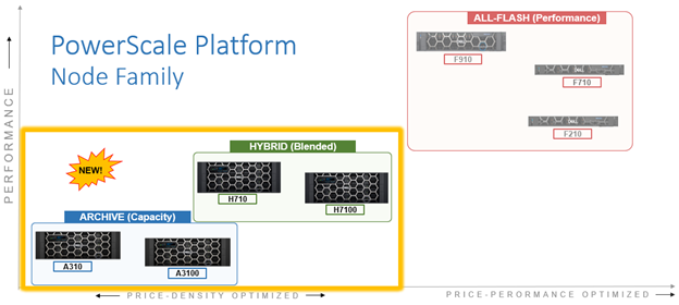
In this article, we’ll examine the new PowerScale A310 and A3100 hardware platforms that were released a couple of weeks back.
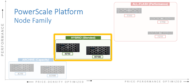
These A310 and A3100 comprise the latest generation of PowerScale A-series ‘archive’ platforms:
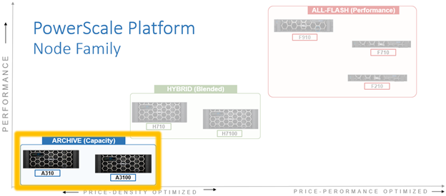
The PowerScale A-series systems are designed for cooler, infrequently accessed data use cases. These include active archive workflows for the A310, such as regulatory compliance data, medical imaging archives, financial records, and legal documents. And deep archive/cold storage for the A3100 platform, including surveillance video archives, backup, and DR repositories.
Representing the archive-tier, the A310 and A3100 both utilize a single-socket Zeon processor with 96GB of memory and fifteen (A310) or twenty hard drives per node respectively, plus SSDs for metadata/caching – and with four nodes residing within a 4RU chassis. From an initial 4 node (1 chassis) starting point, A310 and A31100 clusters can be easily and non-disruptively scaled two nodes at a time up to a maximum of 252 nodes (63 chassis) per cluster.
The A31x modular platform is based on Dell’s ‘Infinity’ chassis. Each node’s compute module contains a single 16-core Intel Sapphire Rapids CPU running at 1.8 GHz and with 22.5MB of cache, plus 96GB of DDR5 DRAM. Front-End networking options include 10/25 GbE and with both Ethernet or Infiniband as selectable options for the back-End network.
As such, the new A31x core hardware specifications are as follows:
| Hardware Class | PowerScale A-Series (Archive) | |
| Model | A310 | A3100 |
| OS version | Requires OneFS 9.11 or above.
Requires NFP 13.1 or greater. BIOS based on Dell’s PowerBIOS |
Requires OneFS 9.11 or above.
Requires NFP 13.1 or greater. BIOS based on Dell’s PowerBIOS |
| Platform | Four nodes per 4RU chassis; upgradeable per pair; node-compatible with prior gens. | Four nodes per 4RU chassis; upgradeable per pair; node-compatible with prior gens. |
| CPU | 8 Cores @ 1.8GHz, 22.5MB Cache | 8 Cores @ 1.8GHz, 22.5MB Cache |
| Memory | 96GB DDR5 DRAM | 96GB DDR5 DRAM |
| Journal | M.2: 480GB NVMe with 3-cell battery backup (BBU) | M.2: 480GB NVMe with 3-cell battery backup (BBU) |
| Depth | Standard 36.7 inch chassis | Deep 42.2 inch chassis |
| Cluster size | Max of 63 chassis (252 nodes) per cluster. | Max of 63 chassis (252 nodes) per cluster. |
| Storage Drives | 60 per chassis (15 per node) | 80 per chassis (20 per node) |
| HDD capacities | 2TB,4TB, 8TB, 12TBTB, 16TB, 20TB, 24TB | 12TBTB, 16TB, 20TB, 24TB |
| SSD (cache) capacities | 0.8TB, 1.6TB, 3.2TB, 7.68TB | 0.8TB, 1.6TB, 3.2TB, 7.68TB |
| Max raw capacity | 1.4PB per chassis | 1.9PB per chassis |
| Front-end network | 10/25 Gb Ethernet | 10/25 Gb Ethernet |
| Back-end network | Ethernet or Infiniband | Ethernet or Infiniband |
These node hardware attributes can be easily viewed from the OneFS CLI via the ‘isi_hw_status’ command. For example, from an A3100:
# isi_hw_status
  SerNo: CF2BC243400025

 Config: H6R28

ChsSerN:

ChsSlot: 1

FamCode: A

ChsCode: 4U

GenCode: 10

PrfCode: 3

   Tier: 3
  Class: storage
 Series: n/a
Product: A3100-4U-Single-96GB-1x1GE-2x25GE SFP+-240TB-6554GB SSD
  HWGen: PSI

Chassis: INFINITY (Infinity Chassis)

    CPU: GenuineIntel (1.80GHz, stepping 0x000806f8)

   PROC: Single-proc, Octa-core

    RAM: 103079215104 Bytes

   Mobo: INFINITYPIFANO (Custom EMC Motherboard)

  NVRam: INFINITY (Infinity Memory Journal) (4096MB card) (size 4294967296B)

 DskCtl: LSI3808 (LSI 3808 SAS Controller) (8 ports)

 DskExp: LSISAS35X36I (LSI SAS35x36 SAS Expander - Infinity)

PwrSupl: Slot1-PS0 (type=ACBEL POLYTECH, fw=03.01)

PwrSupl: Slot2-PS1 (type=ACBEL POLYTECH, fw=03.01)

  NetIF: bge0,lagg0,mce0,mce1,mce2,mce3

 BEType: 25GigE

 FEType: 25GigE

 LCDver: IsiVFD2 (Isilon VFD V2)

 Midpln: NONE (No Midplane Support)

Power Supplies OK

Power Supply Slot1-PS0 good

Power Supply Slot2-PS1 good

CPU Operation (raw 0x882C0800)  = Normal

CPU Speed Limit                 = 100.00%

Fan0_Speed                      = 12360.000

Fan1_Speed                      = 12000.000

Slot1-PS0_In_Voltage            = 212.000

Slot2-PS1_In_Voltage            = 209.000

SP_CMD_Vin                      = 12.100

CMOS_Voltage                    = 3.120

Slot1-PS0_Input_Power           = 290.000

Slot2-PS1_Input_Power           = 290.000

Pwr_Consumption                 = 590.000

SLIC0_Temp                      = na

SLIC1_Temp                      = na

DIMM_Bank0                      = 42.000

DIMM_Bank1                      = 40.000

CPU0_Temp                       = -43.000

SP_Temp0                        = 40.000

MP_Temp0                        = na

MP_Temp1                        = 29.000

Embed_IO_Temp0                  = 51.000

Hottest_SAS_Drv                 = -45.000

Ambient_Temp                    = 29.000

Slot1-PS0_Temp0                 = 47.000

Slot1-PS0_Temp1                 = 40.000

Slot2-PS1_Temp0                 = 47.000

Slot2-PS1_Temp1                 = 40.000

Battery0_Temp                   = 38.000

Drive_IO0_Temp                  = 43.000
Also note that the A310 and A3100 are only available in a 96GB memory configuration.
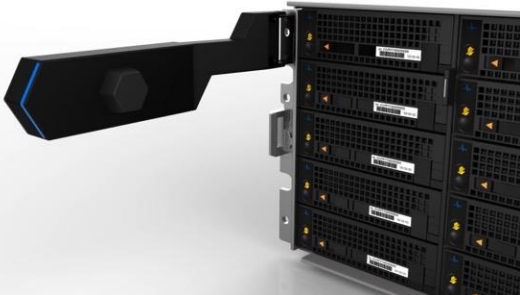
On the front of each chassis is an LCD front panel control with back-lit buttons and 4 LED Light Bar Segments – 1 per Node. These LEDs typically display blue for normal operation or yellow to indicate a node fault. This LCD display is articulating, allowing it to be swung clear of the drive sleds for non-disruptive HDD replacement, etc.
The rear of the chassis houses the compute modules for each node, which contain CPU, memory, networking, cache SSDs, and power supplies. Specifically, an individual compute module contains a multi core Cascade Lake CPU, memory, M2 flash journal, up to two SSDs for L3 cache, six DIMM channels, front end 10/25 Gb ethernet, backend 40/100 or 10/25 Gb ethernet or Infiniband, an ethernet management interface, and power supply and cooling fans:
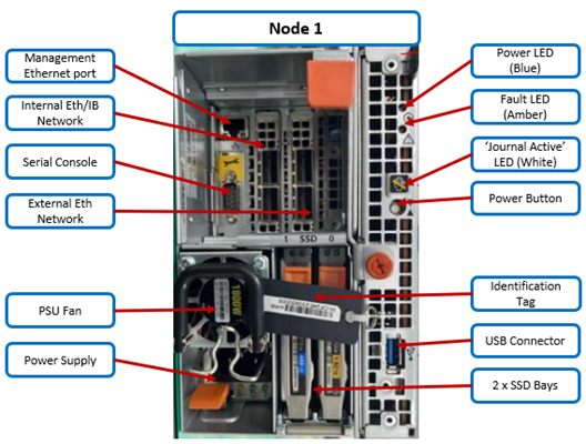
As shown above, the field replaceable components are indicated via colored ‘touchpoints’. Two touchpoint colors, orange and blue, indicate respectively which components are hot swappable versus replaceable via a node shutdown.
| Touchpoint | Detail |
| Blue | Cold (offline) field serviceable component |
| Orange | Hot (Online) field serviceable component |
The serviceable components within an PowerScale A310 or A3100 chassis are as follows:
| Component | Hot Swap | CRU | FRU |
| Drive sled | Yes | Yes | Yes |
| · Hard drives (HDDs) | Yes | Yes | Yes |
| Compute node | No | Yes | Yes |
| · Compute module | No | No | No |
| o M.2 journal flash | No | No | Yes |
| o CPU complex | No | No | No |
| o DIMMs | No | No | Yes |
| o Node fans | No | No | Yes |
| o NICs/HBAs | No | No | Yes |
| o HBA riser | No | No | Yes |
| o Battery backup unit (BBU) | No | No | Yes |
| o DIB | No | No | No |
| · Flash drives (SSDs) | Yes | Yes | Yes |
| · Power supply with fan | Yes | Yes | Yes |
| Front panel | Yes | No | Yes |
| Chassis | No | No | Yes |
| Rail kits | No | No | Yes |
| Mid-plane | Replace entire chassis | ||
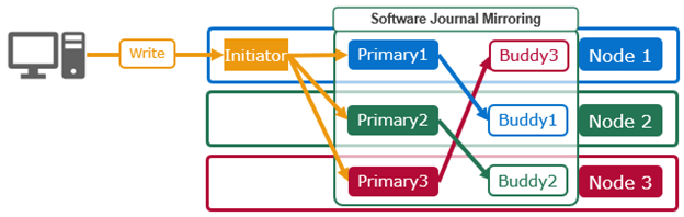
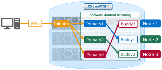
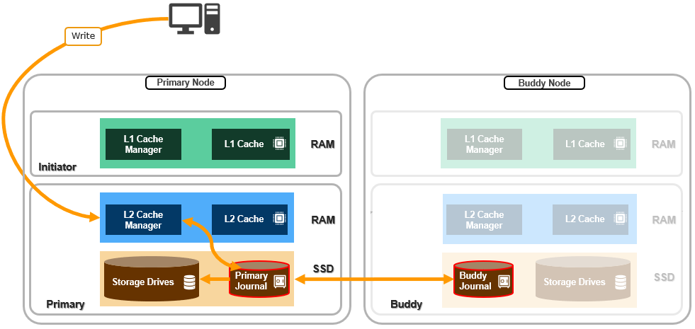
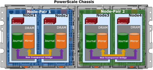
Nodes are paired for resilience and durability, with each pair sharing a mirrored journal and two power supplies:
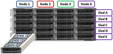
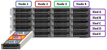
Storage-wise, each of the four nodes within a PowerScale A310/0 chassis’ has five associated drive containers, or sleds. These sleds occupy bays in the front of each chassis, with a node’s drive sleds stacked vertically. For example:

Nodes are numbered 1 through 4, left to right looking at the front of the chassis, while the drive sleds are labeled A through E, with A at the top.
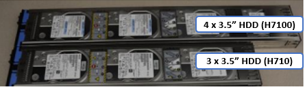
The drive sled is the tray which slides into the front of the chassis. Within each sled, the 3.5” SAS hard drives it contains are numbered sequentially starting from drive zero, which is the HDD adjacent the airdam.
Each bay in a drive sled has a yellow ‘drive fault’ LED associated with each drive:
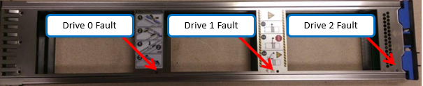
Even when a sled is removed from its chassis and its power source, these fault LEDs will remain active for 10+ minutes. LED viewing holes are also provided so the sled’s top cover does not need to be removed.
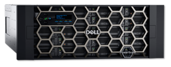
The A3100’s 42.2 inch chassis accommodates four HDDs per sled, compared to three drives for the standard (36.7 inch) depth A310 shown above. As such, the A3100 requires a deep rack, such as the Dell Titan cabinet whereas the A310 can reside in a regular 17” data center cabinet.
The A310 and A3100 platforms support a range of HDD capacities, currently including 2TB, 4, 8, 12, 16, 20, and 24TB capacities, and both regular ISE (instant secure erase) or self-encrypting drive (SED) formats.
A node’s drive details can be queried with OneFS CLI utilities such as ‘isi_radish’ and ‘isi_drivenum’. For example, the command output from an A3100 node:
# isi_drivenum

Bay  1   Unit 6      Lnum 20    Active      SN:GXNG0X800253     /dev/da1
Bay  2   Unit 7      Lnum 21    Active      SN:GXNG0X800263     /dev/da2
Bay  A0   Unit 19     Lnum 16    Active      SN:ZRT1A5JR         /dev/da6
Bay  A1   Unit 18     Lnum 17    Active      SN:ZRT1A4SE         /dev/da5
Bay  A2   Unit 17     Lnum 18    Active      SN:ZRT1A42D         /dev/da4
Bay  A3   Unit 16     Lnum 19    Active      SN:ZRT19494         /dev/da3
Bay  B0   Unit 25     Lnum 12    Active      SN:ZRT18NEY         /dev/da10
Bay  B1   Unit 24     Lnum 13    Active      SN:ZRT1FJCJ         /dev/da9
Bay  B2   Unit 23     Lnum 14    Active      SN:ZRT18N7F         /dev/da8
Bay  B3   Unit 22     Lnum 15    Active      SN:ZRT1FDJL         /dev/da7
Bay  C0   Unit 31     Lnum 8     Active      SN:ZRT1FJ0T         /dev/da14
Bay  C1   Unit 30     Lnum 9     Active      SN:ZRT1F6BF         /dev/da13
Bay  C2   Unit 29     Lnum 10    Active      SN:ZRT1FJMS         /dev/da12
Bay  C3   Unit 28     Lnum 11    Active      SN:ZRT18NE6         /dev/da11
Bay  D0   Unit 37     Lnum 4     Active      SN:ZRT18N9P         /dev/da18
Bay  D1   Unit 36     Lnum 5     Active      SN:ZRT18N8V         /dev/da17
Bay  D2   Unit 35     Lnum 6     Active      SN:ZRT18NBE         /dev/da16
Bay  D3   Unit 34     Lnum 7     Active      SN:ZRT1FR62         /dev/da15
Bay  E0   Unit 43     Lnum 0     Active      SN:ZRT1FDJ4         /dev/da22
Bay  E1   Unit 42     Lnum 1     Active      SN:ZRT1FR86         /dev/da21
Bay  E2   Unit 41     Lnum 2     Active      SN:ZRT1EJ4H         /dev/da20
Bay  E3   Unit 40     Lnum 3     Active      SN:ZRT1E9MS         /dev/da19
The first two lines of output about (bays 1 & 2) reference the cache SSD drives, contained withing the compute modules. The remaining ‘bay’ locations indicate both the sled (A to E) and drive (0 to 3). The presence above of four HDDs per sled (ie. bay numbers 0 to 3) indicate this is an A3100 node, rather than an A310 with only three HDDs per sled.
With regard to the nodes’ internal drives, the boot disk reservation size has increased to 18GB on these new platforms from 8GB on the previous generation. Plus partition sizes have also been expanded on these new platforms in OneFS 9.11, as follows:
| Partition | A310 / A3100 | A300 / A3000 |
| hw | 1GB | 500MB |
| journal backup | 8197MB | 8GB |
| kerneldump | 5GB | 2GB |
| keystore | 64MB | 64MB |
| root | 4GB | 2GB |
| var | 4GB | 2GB |
| var-crash | 7GB | 3GB |
The PowerScale A310 and A3100 platforms are available in the following networking configurations, with a 10/25Gb Ethernet front-end and either Ethernet or Infiniband back-end:
| Model | A310 | A3100 |
| Front-end network | 10/25 GigE | 10/25 GigE |
| Back-end network | 10/25 GigE, Infiniband | 10/25 GigE, Infiniband |
These NICs and their PCI bus addresses can be determined via the ’pciconf’ CLI command, as follows:
# pciconf -l | grep mlx

mlx5_core0@pci0:16:0:0: class=0x020000 card=0x002015b3 chip=0x101f15b3 rev=0x00 hdr=0x00

mlx5_core1@pci0:16:0:1: class=0x020000 card=0x002015b3 chip=0x101f15b3 rev=0x00 hdr=0x00

mlx5_core2@pci0:65:0:0: class=0x020000 card=0x002015b3 chip=0x101f15b3 rev=0x00 hdr=0x00

mlx5_core3@pci0:65:0:1: class=0x020000 card=0x002015b3 chip=0x101f15b3 rev=0x00 hdr=0x00
Similarly, the NIC hardware details and drive firmware versions can be viewed as follows:
# mlxfwmanager

Querying Mellanox devices firmware ...

Device #1:
----------
  Device Type:      ConnectX6LX
  Part Number:      06XJXK_0R5WK9_Ax
  Description:      NVIDIA ConnectX-6 LX Dual Port 25 GbE SFP Network Adapter
  PSID:             DEL0000000031
  PCI Device Name:  pci0:16:0:0
  Base GUID:        58a2e10300e22a24
  Base MAC:         58a2e1e22a24
  Versions:         Current        Available
     FW             26.36.1010     N/A
     PXE            3.6.0901       N/A
     UEFI           14.29.0014     N/A

  Status:           No matching image found

Device #2:
----------
  Device Type:      ConnectX6LX
  Part Number:      06XJXK_0R5WK9_Ax
  Description:      NVIDIA ConnectX-6 LX Dual Port 25 GbE SFP Network Adapter
  PSID:             DEL0000000031
  PCI Device Name:  pci0:65:0:0
  Base GUID:        58a2e10300e22bf4
  Base MAC:         58a2e1e22bf4
  Versions:         Current        Available
     FW             26.36.1010     N/A
     PXE            3.6.0901       N/A
     UEFI           14.29.0014     N/A

  Status:           No matching image found
Compared to their A30x predecessors, the A310 and A3100 see a number of generational hardware upgrades. These include an shift to DDR5 memory, Sapphire Rapids CPU, and an up-spec’d power supply.
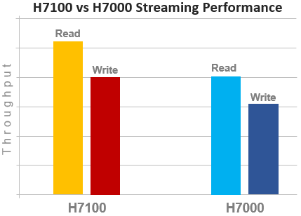
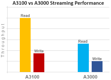
In terms of performance, the new A31x nodes provide a significant increase over the prior generation, as shown in the following streaming read and writes comparison chart for the A3100 and A3000:
OneFS node compatibility provides the ability to have similar node types and generations within the same node pool. In OneFS 9.11 and later, compatibility between the A310 and A3100 nodes and the previous generation platform is supported. Specifically, this node pool compatibility includes:
| OneFS Node Pool Compatibility | Gen6 | MLK | New |
| A200 | A300/L | A310/L | |
| A2000 | A3000/L | A3100/L | |
| H400 | A300 | A310 |
Node pool compatibility checking includes drive capacities, including for both data HDDs and SSD cache. This pool compatibility permits the addition of A310 node pairs to an existing node pool comprising four of more A300s if desired, rather than creating a A310 new node pool. Plus a similar compatibility for A3100/A3000 nodes.
Note that, while the A31x is node pool compatible with the A30x, the A31x nodes are effectively throttled to match the performance envelope of the A30x nodes. Regarding storage efficiency, support for OneFS inline data reduction on mixed A-series diskpools is as follows:
| Gen6 | MLK | New | Data Reduction Enabled |
| A200 | A300/L | A310/L | False |
| A2000 | A3000/L | A3100/L | False |
| H400 | A300 | A310 | False |
| A200 | – | A310 | False |
| – | A300 | A310 | True |
| H400 | – | A310 | False |
| A2000 | – | A3100 | False |
| – | A3000 | A3100 | True |
To summarize, in combination with OneFS 9.11, these new PowerScale hybrid A31x platforms deliver a compelling value proposition in terms of efficiency, density, flexibility, scalability, and affordability.