OneFS Protection Overhead

There have been a number of questions from the field recently around how to calculate the OneFS storage protection overhead for different cluster sizes and protection levels. But first, a quick overview of the fundamentals…

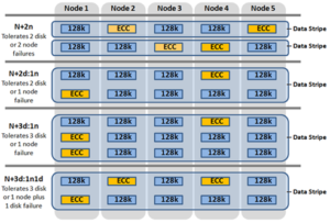
OneFS supports several protection schemes. These include the ubiquitous +2d:1n, which protects against two drive failures or one node failure. The best practice is to use the recommended protection level for a particular cluster configuration. This recommended level of protection is clearly marked as ‘suggested’ in the OneFS WebUI storage pools configuration pages and is typically configured by default. For all current Gen6 hardware configurations, the recommended starting protection level is “+2d:1n’.

The hybrid protection schemes are particularly useful for the chassis-based high-density node configurations, where the probability of multiple drives failing far surpasses that of an entire node failure. In the unlikely event that multiple devices have simultaneously failed, such that the file is “beyond its protection level”, OneFS will re-protect everything possible and report errors on the individual files affected to the cluster’s logs.

OneFS also provides a variety of mirroring options ranging from 2x to 8x, allowing from two to eight mirrors of the specified content. Metadata, for example, is mirrored at one level above FEC by default. For example, if a file is protected at +2n, its associated metadata object will be 3x mirrored.

The full range of OneFS protection levels are as follows:

Protection Level Description
+1n Tolerate failure of 1 drive OR 1 node
+2d:1n Tolerate failure of 2 drives OR 1 node
+2n Tolerate failure of 2 drives OR 2 nodes
+3d:1n Tolerate failure of 3 drives OR 1 node
+3d:1n1d Tolerate failure of 3 drives OR 1 node AND 1 drive
+3n Tolerate failure of 3 drives or 3 nodes
+4d:1n Tolerate failure of 4 drives or 1 node
+4d:2n Tolerate failure of 4 drives or 2 nodes
+4n Tolerate failure of 4 nodes
2x to 8x Mirrored over 2 to 8 nodes, depending on configuration

The charts below show the ‘ideal’ protection overhead across the range of OneFS protection levels and node counts. For each field in this chart, the overhead percentage is calculated by dividing the sum of the two numbers by the number on the right.

x+y => y/(x+y)

So, for a five node cluster protected at +2d:1n, OneFS uses an 8+2 layout – hence an ‘ideal’ overhead of 20%.

8+2 => 2/(8+2) = 20%

Number of nodes [+1n] [+2d:1n] [+2n] [+3d:1n] [+3d:1n1d] [+3n] [+4d:1n] [+4d:2n] [+4n]
3 2 +1 (33%) 4 + 2 (33%) 6 + 3 (33%) 3 + 3 (50%) 8 + 4 (33%)
4 3 +1 (25%) 6 + 2 (25%) 9 + 3 (25%) 5 + 3 (38%) 12 + 4 (25%) 4 + 4 (50%)
5 4 +1 (20%) 8+ 2 (20%) 3 + 2 (40%) 12 + 3 (20%) 7 + 3 (30%) 16 + 4 (20%) 6 + 4 (40%)
6 5 +1 (17%) 10 + 2 (17%) 4 + 2 (33%) 15 + 3 (17%) 9 + 3 (25%) 16 + 4 (20%) 8 + 4 (33%)

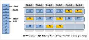
The ‘x+y’ numbers in each field in the table also represent how files are striped across a cluster for each node count and protection level.

Take for example, with +2n protection on a 6-node cluster, OneFS will write a stripe across all 6 nodes, and use two of the stripe units for parity/ECC and four for data.

In general, for FEC protected data the OneFS protection overhead will look something like below.

Note that the protection overhead % (in brackets) is a very rough guide and will vary across different datasets, depending on quantities of small files, etc.

Number of nodes [+1n] [+2d:1n] [+2n] [+3d:1n] [+3d:1n1d] [+3n] [+4d:1n] [+4d:2n] [+4n]
3 2 +1 (33%) 4 + 2 (33%) 6 + 3 (33%) 3 + 3 (50%) 8 + 4 (33%)
4 3 +1 (25%) 6 + 2 (25%) 9 + 3 (25%) 5 + 3 (38%) 12 + 4 (25%) 4 + 4 (50%)
5 4 +1 (20%) 8 + 2 (20%) 3 + 2 (40%) 12 + 3 (20%) 7 + 3 (30%) 16 + 4 (20%) 6 + 4 (40%)
6 5 +1 (17%) 10 + 2 (17%) 4 + 2 (33%) 15 + 3 (17%) 9 + 3 (25%) 16 + 4 (20%) 8 + 4 (33%)
7 6 +1 (14%) 12 + 2 (14%) 5 + 2 (29%) 15 + 3 (17%) 11 + 3 (21%) 4 + 3 (43%) 16 + 4 (20%) 10 + 4 (29%)
8 7 +1 (13%) 14 + 2 (12.5%) 6 + 2 (25%) 15 + 3 (17%) 13 + 3 (19%) 5 + 3 (38%) 16 + 4 (20%) 12 + 4 (25%)
9 8 +1 (11%) 16 + 2 (11%) 7 + 2 (22%) 15 + 3 (17%) 15 + 3 (17%) 6 + 3 (33%) 16 + 4 (20%) 14 + 4 (22%) 5 + 4 (44%)
10 9 +1 (10%) 16 + 2 (11%) 8 + 2 (20%) 15 + 3 (17%) 15 + 3 (17%) 7 + 3 (30%) 16 + 4 (20%) 16 + 4 (20%) 6 + 4 (40%)
12 11 +1 (8%) 16 + 2 (11%) 10 + 2 (17%) 15 + 3 (17%) 15 + 3 (17%) 9 + 3 (25%) 16 + 4 (20%) 16 + 4 (20%) 6 + 4 (40%)
14 13 +1 (7%) 16 + 2 (11%) 12 + 2 (14%) 15 + 3 (17%) 15 + 3 (17%) 11 + 3 (21%) 16 + 4 (20%) 16 + 4 (20%) 10 + 4 (29%)
16 15 +1 (6%) 16 + 2 (11%) 14 + 2 (13%) 15 + 3 (17%) 15 + 3 (17%) 13 + 3 (19%) 16 + 4 (20%) 16 + 4 (20%) 12 + 4 (25%)
18 16 +1 (6%) 16 + 2 (11%) 16 + 2 (11%) 15 + 3 (17%) 15 + 3 (17%) 15 + 3 (17%) 16 + 4 (20%) 16 + 4 (20%) 14 + 4 (22%)
20 16 +1 (6%) 16 + 2 (11%) 16 + 2 (11%) 16 + 3 (16%) 16 + 3 (16%) 16 + 3 (16%) 16 + 4 (20%) 16 + 4 (20%) 14 + 4 (22%)
30 16 +1 (6%) 16 + 2 (11%) 16 + 2 (11%) 16 + 3 (16%) 16 + 3 (16%) 16 + 3 (16%) 16 + 4 (20%) 16 + 4 (20%) 14 + 4 (22%)

The protection level of the file is how the system decides to layout the file. A file may have multiple protection levels temporarily (because the file is being restriped) or permanently (because of a heterogeneous cluster). The protection level is specified as “n + m/b@r” in its full form. In the case where b, r, or both equal 1, it may be elided to get “n + m/b”, “n + m@r”, or “n + m”.

Layout Attribute Description
N Number of data drives in a stripe.
+m Number of FEC drives in a stripe.
/b Number of drives per stripe allowed on one node.
@r Number of drives to include in the layout of a file.

The OneFS protection definition in terms of node and/or drive failures has the advantage of configuration simplicity. However, it does mask some of the subtlety of the interaction between stripe width and drive spread, as represented by the n+m/b notation displayed by the ‘isi get’ CLI command. For example:

# isi get README.txt

POLICY    LEVEL PERFORMANCE COAL  FILE

default   6+2/2 concurrency on    README.txt

In particular, both +3/3 and +3/2 allow for a single node failure or three drive failures and appear the same according to the web terminology. Despite this, they do in fact have different characteristics. +3/2 allows for the failure of any one node in combination with the failure of a single drive on any other node, which +3/3 does not. +3/3, on the other hand, allows for potentially better space efficiency and performance because up to three drives per node can be used, rather than the 2 allowed under +3/2.

That said, the protection level does have a minor affect on write performance. The largest impact is from the first number after the + in the protection level. For example, the the ‘+2’ levels (including +2n or +2d:1n) may be around 3% faster than the ‘+3’ levels (including +3n, +3d:1n1d, or +3d:1n). There is also some variation on depending on the number of nodes in a cluster, but typically this is less significant.

Another factor to keep in mind is OneFS neighborhoods. A neighborhood is a fault domains within a node pool, and their purpose is to improve reliability in general – and guard against data unavailability from the accidental removal of Gen6 drive sleds. For self-contained nodes like the PowerScale F200, OneFS has an ideal size of 20 nodes per node pool, and a maximum size of 39 nodes. On the addition of the 40th node, the nodes split into two neighborhoods of twenty nodes.

With the Gen6 platform, the ideal size of a neighborhood changes from 20 to 10 nodes. This 10-node ideal neighborhood size helps protect the Gen6 architecture against simultaneous node-pair journal failures and full chassis failures. Partner nodes are nodes whose journals are mirrored. Rather than each node storing its journal in NVRAM as in the PowerScale platforms, the Gen6 nodes’ journals are stored on SSDs – and every journal has a mirror copy on another node. The node that contains the mirrored journal is referred to as the partner node. There are several reliability benefits gained from the changes to the journal. For example, SSDs are more persistent and reliable than NVRAM, which requires a charged battery to retain state. Also, with the mirrored journal, both journal drives have to die before a journal is considered lost. As such, unless both of the mirrored journal drives fail, both of the partner nodes can function as normal.

With partner node protection, where possible, nodes will be placed in different neighborhoods – and hence different failure domains. Partner node protection is possible once the cluster reaches five full chassis (20 nodes) when, after the first neighborhood split, OneFS places partner nodes in different neighborhoods:

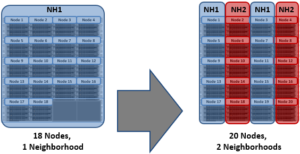
Partner node protection increases reliability because if both nodes go down, they are in different failure domains, so their failure domains only suffer the loss of a single node.

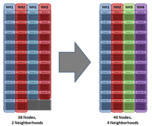
With chassis protection, when possible, each of the four nodes within a chassis will be placed in a separate neighborhood. Chassis protection becomes possible at 40 nodes, as the neighborhood split at 40 nodes enables every node in a chassis to be placed in a different neighborhood. As such, when a 38 node Gen6 cluster is expanded to 40 nodes, the two existing neighborhoods will be split into four 10-node neighborhoods:

Chassis protection ensures that if an entire chassis failed, each failure domain would only lose one node.


Better Protection with Dell EMC ECS Object Lock

Dell EMC ECS supported WORM (write-once-read-many) based retention from ECS 2.X. However, to gain more compatibility with more applications, ECS support the object lock feature from 3.6.2 version which is compatible with the capabilities of Amazon S3 object lock.

Dell EMC ECS object lock protects object versions from accidental or malicious deletion such as a ransomware attack. It does this by allowing object versions to enter a Write Once Read Many (WORM) state where access is restricted based on attributes set on the object version.

Object lock is designed to meet compliance requirements such as SEC 17a4(f), FINRA Rule 4511(c), and CFTC Rule 17.

Object lock overview

Object lock prevents object version deletion during a user-defined retention period.  Immutable S3 objects are protected using object- or bucket-level configuration of WORM and retention attributes. The retention policy is defined using the S3 API or bucket-level defaults.  Objects are locked for the duration of the retention period, and legal hold scenarios are also supported.

There are two lock types for object lock:

  • Retention period — Specifies a fixed period of time during which an object version remains locked. During this period, your object version is WORM-protected and can’t be overwritten or deleted.
  • Legal hold — Provides the same protection as a retention period, but it has no expiration date. Instead, a legal hold remains in place until you explicitly remove it. legal holds are independent from retention periods.

There are two mode for the retention period:

  • Governance mode — users can’t overwrite or delete an object version or alter its lock settings unless they have special permissions. With governance mode, you protect objects against being deleted by most users, but you can still grant some users permission to alter the retention settings or delete the object if necessary. You can also use governance mode to test retention-period settings before creating a compliance-mode retention period.
  • Compliance mode — a protected object version can’t be overwritten or deleted by any user, including the root user in your account. When an object is locked in compliance mode, its retention mode can’t be changed, and its retention period can’t be shortened. Compliance mode helps ensure that an object version can’t be overwritten or deleted for the duration of the retention period.

Object lock and lifecycle

Objects under lock are protected from lifecycle deletions.

Lifecycle logic is made difficult due to variety of behavior of different locks. From lifecycle point of view there are locks without a date, locks with date that can be extended, and locks with date that can be decreased.

  • For compliance mode, the retain until date can’t be decreased, but can be increased:
  • For governance mode, the lock date can increase, decrease, or get removed.
  • For legal hold, the lock is indefinite.

Some key points for the S3 object lock with ECS

  • Object lock requires FS (File System) disabled on bucket in ECS 3.6.2 version.
  • Object lock requires ADO (Access During Outage) disabled on bucket in ECS 3.6.2 version.
  • Object lock is only supported by S3 API, not UI workflows in ECS 3.6.2 version.
  • Object lock only works with IAM, not legacy accounts.
  • Object lock works only in versioned buckets.
  • Enabling locking on the bucket automatically makes it versioned.
  • Once bucket locking is enabled, it is not possible to disable object lock or suspend versioning for the bucket.
  • A bucket has default configuration include a retention mode (governance or compliance) and also a retention period (which is days or years).
  • Object locks apply to individual object versions only.
  • Different versions of a single object can have different retention modes and periods.
  • Lock prevents an object from being deleted or overwritten. Overwritten does not mean that new versions can’t be created (new version can be created with their own lock settings).
  • Object can still be deleted; it will create a delete marker and the version still exists and is locked.
  • Compliance mode is stricter, locks can’t be removed, decreased, or downgraded to governance mode.
  • Governance mode is less strict, it can be removed, bypassed, elevated to compliance mode.
  • Object can still be deleted, but the version still exists and is locked.
  • Updating an object version’s metadata, as occurs when you place or alter an object lock, doesn’t overwrite the object version or reset its Last-Modified timestamp.
  • Retention period can be placed on an object explicitly, or implicitly through a bucket default setting.
  • Placing a default retention setting on a bucket doesn’t place any retention settings on objects that already exist in the bucket.
  • Changing a bucket’s default retention period doesn’t change the existing retention period for any objects in that bucket.
  • object lock and traditional bucket/object ECS retention can co-exist.

ECS object lock condition keys

Access control using IAM policies is an important part of the object lock functionality. The s3:BypassGovernanceRetention permission is important since it is required to delete a WORM-protected object in Governance mode.  IAM policy conditions have been defined below to allow you to limit what retention period and legal hold can be specified in objects.

Condition Key Description
s3:object-lock-legal-hold Enables enforcement of the specified object legal hold status
s3:object-lock-mode Enables enforcement of the specified object retention mode
s3:object-lock-retain-until-date Enables enforcement of a specific retain-until-date
s3:object-lock-remaining-retention-days Enables enforcement of an object relative to the remaining retention days

ECS object lock API examples

This section lists s3curl examples of object Lock APIs. Put and Get object lock APIs can be used with and without versionId parameter. If no versionId parameter is used, then the action applies to the latest version.

Operation API request examples
Create lock-enabled bucket s3curl.pl –id=ecsflex –createBucket — http://${s3ip}/mybucket

-H “x-amz-bucket-object-lock-enabled: true”

Enable object lock on existing bucket s3curl.pl –id=ecsflex — http://${s3ip}/my-bucket?enable-objectlock

-X PUT

Get bucket default lock configuration s3curl.pl –id=ecsflex — http://${s3ip}/my-bucket?object-lock
Put bucket default lock

configuration

s3curl.pl –id=ecsflex — http://${s3ip}/my-bucket?object-lock

-X PUT \

-d “<ObjectLockConfiguration><ObjectLockEnabled>Enabled</

ObjectLockEnabled>

<Rule><DefaultRetention><Mode>GOVERNANCE</Mode><Days>1</Days></

DefaultRetention></Rule></ObjectLockConfiguration>”

Get legal hold s3curl.pl –id=ecsflex — http://${s3ip}/my-bucket/obj?legal-hold
Put legal hold on create s3curl.pl –id=ecsflex –put=/root/100b.file — http://${s3ip}/

my-bucket/obj -H “x-amz-object-lock-legal-hold: ON”

Put legal hold on existing object s3curl.pl –id=ecsflex — http://${s3ip}/my-bucket/obj?legalhold

-X PUT -d “<LegalHold><Status>OFF</Status></LegalHold>”

Get retention s3curl.pl –id=ecsflex — http://${s3ip}/my-bucket/obj?retention
Put retention on create s3curl.pl –id=ecsflex –put=/root/100b.file — http://${s3ip}/

my-bucket/obj -H “x-amz-object-lock-mode: GOVERNANCE” -H “x-amz-object-lock-retain-until-date: 2030-01-01T00:00:00.000Z”

Put retention on existing object s3curl.pl –id=ecsflex — http://${s3ip}/my-bucket/obj?

retention -X PUT -d “<Retention><Mode>GOVERNANCE</

Mode><RetainUntilDate>2030-01-01T00:00:00.000Z</

RetainUntilDate></Retention>”

Put retention on existing

object (with bypass)

s3curl.pl –id=ecsflex — http://${s3ip}/my-bucket/obj?

retention -X PUT -d “<Retention><Mode>GOVERNANCE</

Mode><RetainUntilDate>2030-01-01T00:00:00.000Z</

RetainUntilDate></Retention>” -H “x-amz-bypass-governance-retention:

true”


OneFS and SMB Encryption

Received a couple of recent questions around SMB encryption, which is supported in addition to the other components of the SMB3 protocol dialect that OneFS supports, including multi-channel, continuous availability (CA), and witness.

OneFS allows encryption for SMB3 clients to be configured on a per share, zone, or cluster-wide basis. When configuring encryption at the cluster-wide level, OneFS provides the option to also allow unencrypted connections for older, non-SMB3 clients.

The following CLI command will indicate whether SMB3 encryption has already been configured globally on the cluster:

# isi smb settings global view | grep -i encryption

    Support Smb3 Encryption: No

The following table lists what behavior a variety of Microsoft Windows and Apple Mac OS versions will support with respect to SMB3 encryption:

Operating System Description
Windows Vista/Server 2008 Can only access non-encrypted shares if cluster is configured to allow non-encrypted connections
Windows 7/Server 2008 R2 Can only access non-encrypted shares if cluster is configured to

allow non-encrypted connections

Windows 8/Server 2012 Can access encrypted share (and non-encrypted shares if cluster is configured to allow non-encrypted connections)
Windows 8.1/Server 2012 R2 Can access encrypted share (and non-encrypted shares if cluster is configured to allow non-encrypted connections)
Windows 10/Server 2016 Can access encrypted share (and non-encrypted shares if cluster is configured to allow non-encrypted connections)
OSX10.12 Can access encrypted share (and non-encrypted shares if cluster is configured to allow non-encrypted connections)

Note that only operating systems which support SMB3 encryption can work with encrypted shares. These operating systems can also work with unencrypted shares, but only if the cluster is configured to allow non-encrypted connections. Other operating systems can access non-encrypted shares only if the cluster is configured to allow non-encrypted connections.

If encryption is enabled for an existing share or zone, and if the cluster is set to only allow encrypted connections, only Windows 8/Server 2012 and later and OSX 10.12 will be able to access that share or zone. Encryption cannot be turned on or off at the client level.

The following CLI procedures will configure SMB3 encryption on a specific share, rather than globally across the cluster:

As a prerequisite, ensure that the cluster and clients are bound and connected to the desired Active Directory domain (for example in this case, ad1.com).

To create a share with SMB3 encryption enabled from the CLI:

# mkdir -p /ifs/smb/data_encrypt
# chmod +a group "AD1\\Domain Users" allow generic_all /ifs/smb/data_encrypt
# isi smb shares create DataEncrypt /ifs/smb/data_encrypt --smb3-encryption-enabled true
# isi smb shares permission modify DataEncrypt --wellknown Everyone -d allow -p full

To verify that an SMB3 client session is actually being encrypted, launch a remote desktop protocol (RDP) session to the Windows client, log in as administrator, and perform the following:

  1. Ensure a packet capture and analysis tool such as Wireshark is installed.
  2. Start Wireshark capture using the capture filter “port 445
  3. Map the DataEncrypt share from the second node in the cluster
  4. Create a file on the desktop on the client (eg. README-W10.txt).
  5. Copy the README-W10.txt file from the Desktop on the client to the DataEncrypt shares using Windows explorer.exe
  6. Stop the Wireshark capture
  7. Set the Wireshark the display filter to “smb2 and ip.addr for node 1
    1. Examine the SMB2_NEGOTIATE packet exchange to verify the capabilities, negotiated contexts and protocol dialect (3.1.1)
    2. Examine the SMB2_TREE_CONNECT to verify the that encryption support has not been enabled for this share
    3. Examine the SMB2_WRITE requests to ensure that the file contents are readable.
  8. Set the Wireshark the display filter to “smb2 and ip.addr for node 2
    1. Examine the SMB2_NEGOTIATE packet exchange to verify the capabilities, negotiated contexts and protocol dialect (3.1.1)
    2. Examine the SMB2_TREE_CONNECT to verify the that encryption support has been enabled for this share
    3. Examine the communication following the successful SMB2_TREE_CONNECT response that the packets are encrypted
  9. : Save the Wireshark Capture to the DataEncrypt share using the name Win10-SMB3EncryptionDemo.pcap.

SMB3 encryption can also be applied globally to a cluster. This will mean that all the SMB communication with the cluster will be encrypted, not just with individual shares. SMB clients that don’t support SMB3 encryption will only be able to connect to the cluster so long as it is configured to allow non-encrypted connections. The following table presents the available global SMB3 encryption config options:

Setting Description
Disabled Encryption for SMBv3 clients in not enabled on this cluster.
Enable SMB3 encryption Permits encrypted SMBv3 client connections to Isilon clusters, but does not make encryption mandatory. Unencrypted SMBv3 clients can still connect to the cluster when this option is enabled. Note that this setting does not actively enable SMBv3 encryption: To encrypt SMBv3 client connections to the cluster, you must first select this option and then activate encryption on the client side. This setting applies to all shares in the cluster.


Reject unencrypted SMB3 client connections Makes encryption mandatory for all SMBv3 client connections to the cluster. When this setting is active, only encrypted SMBv3 clients can connect to the cluster. SMBv3 clients that do not have encryption enabled are denied access. This setting applies to all shares in the cluster.

The following CLI syntax will configure global SMB3 encryption:

# isi smb settings global modify --support-smb3-encryption=yes

Verify the global encryption settings on a cluster by running:

# isi smb settings global view | grep -i encrypt

  Reject Unencrypted Access: Yes

    Support Smb3 Encryption: Yes

Global SMB3 encryption can also be enabled from the WebUI by browsing to Protocols > Windows Sharing (SMB) > SMB Server Settings:


OneFS Quota Accounting

Had a couple of recent enquiries from the field regarding SmartQuotas performance. So in this article we’ll explore one of the more obscure tuning parameters of OneFS SmartQuotas.

Under the hood, SmartQuotas quota data is maintained in Quota Accounting Blocks (QABs). Each QAB contains a large number of accounting records, which need to be updated whenever a particular user adds or removes data from the quota domain, the area of the filesystem on which quotas are enabled.  If a large quantity of clients are simultaneously accessing the quota domain, these blocks can become highly contended and a potential bottleneck. Similarly, if a single client (or small number of clients) consistently makes a large number of small writes to files within a single quota, write performance could again be impacted

To address this, quota accounts have a mechanism to help avoid hot spots on those nodes which are storing QABs. This can be addressed using Quota Account Constituents, or QACs, which help parallelize the accounting. QACs can boost the performance of quota accounting by creating additional QAB mirrors, which are distributed across the cluster.

QAC configuration is via the sysctl ‘efs.quota.reorganize.qac_ratio’, which increases the number of accounting constituents, which are in turn spread across a much larger number of nodes and drives. This provides better scalability by increasing aggregate throughput and reduces latencies on heavy create/delete activities when quotas are configured.

Using this parameter, the internally calculated QAC count for each quota is multiplied by the specified value. If a workflow experiences write performance issues, and it has many writes to files or directories governed by a single quota, then increasing the QAC ratio may significantly improve write performance.

The qac_ratio can be reconfigured to from its default value of none up to the maximum value of 8 via the following CLI command:

# isi_sysctl_cluster efs.quota.reorganize.qac_ratio=8

To verify the persistent change, run:

# cat /etc/mcp/override/sysctl.conf | grep qac_ratio

Although increasing the QAC count via this sysctl can improve performance on write heavy quota domains, some amount of experimentation may be required until the ideal QAC ratio value is found.

Adjusting the ‘qac_ratio’ sysctl parameter can adversely affect write performance if you apply a value that is too high, or if you apply the parameter in an environment that does not have diminished write performance due to quota contention.

To help assess write performance while tuning the QAC ration, write latency (TimeAvg) for the NFSv3 protocol, for example, can continuously be monitored by running the following CLI command:

# isi statistics protocol --protocols nfs3 --classes write --output TimeAvg --format top

OneFS Hardware Fault Tolerance

There have been several inquiries recently around PowerScale clusters and hardware fault tolerance, above and beyond file level data protection via erasure coding. So it seemed like a useful topic for a blog article, and here are some of the techniques which OneFS employs to help protect data against the threat of hardware errors:

File system journal

Every PowerScale node is equipped with a battery backed NVRAM file system journal. Each journal is used by OneFS as stable storage, and guards write transactions against sudden power loss or other catastrophic events. The journal protects the consistency of the file system and the battery charge lasts up to three days. Since each member node of a cluster contains an NVRAM controller, the entire OneFS file system is therefore fully journaled.

Proactive device failure

OneFS will proactively remove, or SmartFail, any drive that reaches a particular threshold of detected Error Correction Code (ECC) errors, and automatically reconstruct the data from that drive and locate it elsewhere on the cluster. Both SmartFail and the subsequent repair process are fully automated and hence require no administrator intervention.

Data integrity

ISI Data Integrity (IDI) is the OneFS process that protects file system structures against corruption via 32-bit CRC checksums. All OneFS blocks, both for file and metadata, utilize checksum verification. Metadata checksums are housed in the metadata blocks themselves, whereas file data checksums are stored as metadata, thereby providing referential integrity. All checksums are recomputed by the initiator, the node servicing a particular read, on every request.

In the event that the recomputed checksum does not match the stored checksum, OneFS will generate a system alert, log the event, retrieve and return the corresponding error correcting code (ECC) block to the client and attempt to repair the suspect data block.

Protocol checksums

In addition to blocks and metadata, OneFS also provides checksum verification for Remote Block Management (RBM) protocol data. As mentioned above, the RBM is a unicast, RPC-based protocol used over the back-end cluster interconnect. Checksums on the RBM protocol are in addition to the InfiniBand hardware checksums provided at the network layer, and are used to detect and isolate machines with certain faulty hardware components and exhibiting other failure states.

Dynamic sector repair

OneFS includes a Dynamic Sector Repair (DSR) feature whereby bad disk sectors can be forced by the file system to be rewritten elsewhere. When OneFS fails to read a block during normal operation, DSR is invoked to reconstruct the missing data and write it to either a different location on the drive or to another drive on the node. This is done to ensure that subsequent reads of the block do not fail. DSR is fully automated and completely transparent to the end-user. Disk sector errors and Cyclic Redundancy Check (CRC) mismatches use almost the same mechanism as the drive rebuild process.

MediaScan

MediaScan’s role within OneFS is to check disk sectors and deploy the above DSR mechanism in order to force disk drives to fix any sector ECC errors they may encounter. Implemented as one of the phases of the OneFS job engine, MediaScan is run automatically based on a predefined schedule. Designed as a low-impact, background process, MediaScan is fully distributed and can thereby leverage the benefits of a cluster’s parallel architecture.

IntegrityScan

IntegrityScan, another component of the OneFS job engine, is responsible for examining the entire file system for inconsistencies. It does this by systematically reading every block and verifying its associated checksum. Unlike traditional ‘fsck’ style file system integrity checking tools, IntegrityScan is designed to run while the cluster is fully operational, thereby removing the need for any downtime. In the event that IntegrityScan detects a checksum mismatch, a system alert is generated and written to the syslog and OneFS automatically attempts to repair the suspect block.

The IntegrityScan phase is run manually if the integrity of the file system is ever in doubt. Although this process may take several days to complete, the file system is online and completely available during this time. Additionally, like all phases of the OneFS job engine, IntegrityScan can be prioritized, paused or stopped, depending on the impact to cluster operations and other jobs.

Fault isolation

Because OneFS protects its data at the file-level, any inconsistencies or data loss is isolated to the unavailable or failing device—the rest of the file system remains intact and available.

For example, a ten node, S210 cluster, protected at +2d:1n, sustains three simultaneous drive failures—one in each of three nodes. Even in this degraded state, I/O errors would only occur on the very small subset of data housed on all three of these drives. The remainder of the data striped across the other two hundred and thirty-seven drives would be totally unaffected. Contrast this behavior with a traditional RAID6 system, where losing more than two drives in a RAID-set will render it unusable and necessitate a full restore from backups.

Similarly, in the unlikely event that a portion of the file system does become corrupt (whether as a result of a software or firmware bug, etc) or a media error occurs where a section of the disk has failed, only the portion of the file system associated with this area on disk will be affected. All healthy areas will still be available and protected.

As mentioned above, referential checksums of both data and meta-data are used to catch silent data corruption (data corruption not associated with hardware failures).The checksums for file data blocks are stored as metadata, outside the actual blocks they reference, and thus provide referential integrity.

Accelerated drive rebuilds

The time that it takes a storage system to rebuild data from a failed disk drive is crucial to the data reliability of that system. With the advent of four terabyte drives, and the creation of increasingly larger single volumes and file systems, typical recovery times for multi-terabyte drive failures are becoming multiple days or even weeks. During this MTTDL period, storage systems are vulnerable to additional drive failures and the resulting data loss and downtime.

Since OneFS is built upon a highly distributed architecture, it’s able to leverage the CPU, memory and spindles from multiple nodes to reconstruct data from failed drives in a highly parallel and efficient manner. Because a PowerScale cluster is not bound by the speed of any particular drive, OneFS is able to recover from drive failures extremely quickly and this efficiency grows relative to cluster size. As such, a failed drive within a cluster will be rebuilt an order of magnitude faster than hardware RAID-based storage devices. Additionally, OneFS has no requirement for dedicated ‘hot-spare’ drives.

Automatic drive firmware updates

Clusters support automatic drive firmware updates for new and replacement drives, as part of the non-disruptive firmware update process. Firmware updates are delivered via drive support packages, which both simplify and streamline the management of existing and new drives across the cluster. This ensures that drive firmware is up to date and mitigates the likelihood of failures due to known drive issues. As such, automatic drive firmware updates are an important component of OneFS’ high availability and non-disruptive operations strategy.

OneFS Protocol Auditing

Auditing can detect potential sources of data loss, fraud, inappropriate entitlements, access attempts that should not occur, and a range of other anomalies that are indicators of risk. This can be especially useful when the audit associates data access with specific user identities.

In the interests of data security, OneFS provides ‘chain of custody’ auditing by logging specific activity on the cluster. This includes OneFS configuration changes plus NFS, SMB, and HDFS client protocol activity, which are required for organizational IT security compliance, as mandated by regulatory bodies like HIPAA, SOX, FISMA, MPAA, etc.

OneFS auditing uses Dell EMC’s Common Event Enabler (CEE) to provide compatibility with external audit applications.

A cluster can write audit events across up to five CEE servers per node in a parallel, load-balanced configuration. This allows OneFS to deliver an end to end, enterprise grade audit solution which efficiently integrates with third party solutions like Varonis DatAdvantage.

OneFS auditing provides control over exactly what protocol activity is audited. For example:

  • Stops collection of unneeded audit events that 3rd party applications do not register for
  • Reduces the number of audit events collected to only what is needed. Less unneeded events are stored on ifs and sent off cluster.

OneFS protocol auditing events are configurable at CEE granularity, with each OneFS event mapping directly to a CEE event. This allows customers to configure protocol auditing to collect only what their auditing application requests, reducing both the number of events discarded by CEE and stored on /ifs.

The ‘isi audit settings’ command syntax and corresponding platformAPI are used to specify the desired events for the audit filter to collect.

A ‘detail_type’ field within OneFS internal protocol audit events allows a direct mapping to CEE audit events. For example:

“protocol":"SMB2",

"zoneID":1,

"zoneName":"System",

"eventType":"rename",

"detailType":"rename-directory",

"isDirectory":true,

"clientIPAddr":"10.32.xxx.xxx",

"fileName":"\\ifs\\test\\New folder",

"newFileName":"\\ifs\\test\\ABC",

"userSID":"S-1-22-1-0",

"userID":0,

Old audit events are processed and mapped to the same CEE audit events as in previous releases. Backwards compatibility is maintained with previous audit events such that old versions ignore the new field. There are no changes to external audit events sent to CEE or syslog.

  • New default audit events when creating an access zone

Here are the protocol audit events:

New OneFS Audit Event Pre-8.2 Audit Event
create_file create
create_directory create
open_file_write create
open_file_read create
open_file_noaccess create
open_directory create
close_file_unmodified close
close_file_modified close
close_directory close
delete_file delete
delete_directory delete
rename_file rename
rename_directory rename
set_security_file set_security
set_security_directory set_security
get_security_file, get_security
get_security_directory get_security
write_file write
read_file read


Audit Event
logon
logoff
tree_connect

The ‘isi audit settings’ CLI command syntax is a follows:

Usage:

    isi audit <subcommand>

Subcommands:

    settings    Manage settings related to audit configuration.

    topics      Manage audit topics.

    logs        Delete out of date audit logs manually & monitor process.

    progress    Get the audit event time.

All options that take <events> use the protocol audit events:

# isi audit settings view –zone=<zone>

# isi audit settings modify --audit-success=<events> --zone=<zone>

# isi audit settings modify --audit-failure=<events> --zone=<zone>

# isi audit settings modify --syslog-audit-events=<events> --zone=<zone>

When it comes to troubleshooting audit on a cluster, the ‘isi_audit_viewer’ utility can be used to list protocol audit events collected.

# isi_audit_viewer -h

Usage: isi_audit_viewer [ -n <nodeid> | -t <topic> | -s <starttime>|

         -e <endtime> | -v ]

         -n <nodeid> : Specify node id to browse (default: local node)

         -t <topic>  : Choose topic to browse.

            Topics are "config" and "protocol" (default: "config")

         -s <start>  : Browse audit logs starting at <starttime>

         -e <end>    : Browse audit logs ending at <endtime>

         -v verbose  : Prints out start / end time range before printing

             records

The new audit event type is in the ‘detail_type’ field. Additionally, any errors that are encountered while processing audit events, and when delivering them to an external CEE server, are written to the log file/var/log/isi_audit_cee.log’. Additionally, the protocol specific logs will contain any issues the audit filter has collecting while auditing events.

These protocol log files are:

Protocol Log file
HDFS /var/log/hdfs.log
NFS /var/log/nfs.log
SMB /var/log/lwiod.log
S3 /var/log/s3.log

Note that, on large clusters were there is heavy 100,000 of audit writes, when running the isi_audit_viewer utility across the cluster with ‘isi_for_array’, it can potentially lead to memory and other issues – especially if outputting to a directory under /ifs. As such, consider directing the output to an non-IFS location such as /var/temp.  Also, the isi_audit_viewer ‘-s’ (start time) and ‘-e’ (end time) flags can be used to limit a search (ie. for  1-5 minutes), helping reduce the size of data.