OneFS HTTP Services and Security

To facilitate granular HTTP security configuration, OneFS provides an option to disable nonessential HTTP components selectively. Disabling a specific component’s service still allows other essential services on the cluster to continue to run unimpeded. In OneFS 9.4 and later, the following nonessential HTTP services may be disabled:

Service Description
PowerScaleUI The OneFS WebUI configuration interface.
Platform-API-External External access to the OneFS platform API endpoints.
Rest Access to Namespace (RAN) REST-ful access via HTTP to a cluster’s /ifs namespace.
RemoteService Remote Support and In-Product Activation.
SWIFT (deprecated) Deprecated object access to the cluster via the SWIFT protocol. This has been replaced by the S3 protocol in OneFS.

Each of these services may be enabled or disabled independently via the CLI or platform API by a user account with the ISI_PRIV_HTTP RBAC privilege.

The ‘isi http services’ CLI command set can be used to view and modify the nonessential services HTTP services:

# isi http services list

ID                    Enabled

------------------------------

Platform-API-External Yes

PowerScaleUI          Yes

RAN                   Yes

RemoteService         Yes

SWIFT                 No

------------------------------

Total: 5

For example, remote HTTP access to the OneFS /ifs namespace can easily be disabled as follows:

 # isi http services modify RAN --enabled=0

You are about to modify the service RAN. Are you sure? (yes/[no]): yes

Similarly, a subset of the HTTP configuration settings can also be viewed and edited via the WebUI by navigating to Protocols > HTTP settings:

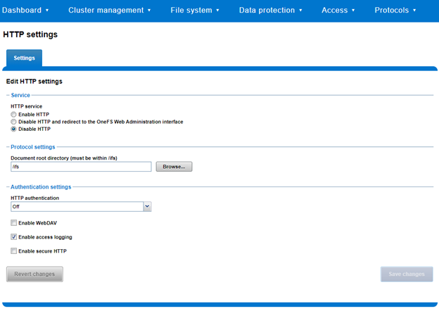
That said, the implications and impact of disabling each of the services is as follows:

Service Disabling Impacts
WebUI The WebUI is completely disabled, and access attempts (default TCP port 8080) are denied with the following warning:

“Service Unavailable. Please contact Administrator.”

If the WebUI is re-enabled, the external platform API service (Platform-API-External) is also started if it is not running. Note that disabling the WebUI does not affect the PlatformAPI service.

Platform API External API requests to the cluster are denied, and the WebUI is disabled, since it uses the Platform-API-External service.

Note that the Platform-API-Internal service is not impacted if/when the Platform-API-External is disabled, and internal pAPI services continue to function as expected.

If the Platform-API-External service is re-enabled, the WebUI will remain inactive until the PowerScaleUI service is also enabled.

RAN If RAN is disabled, the WebUI components for File System Explorer and File Browser are also automatically disabled.

From the WebUI, attempts to access the OneFS file system explorer (File System > File System Explorer) fail with the following warning message:

“Browse is disabled as RAN service is not running. Contact your administrator to enable the service.”

This same warning is also displayed when attempting to access any other WebUI components that require directory selection.

RemoteService If RemoteService is disabled, the WebUI components for Remote Support and In-Product Activation are disabled.

In the WebUI, going to Cluster Management > General Settings and selecting the Remote Support tab displays the following message:

“The service required for the feature is disabled. Contact your administrator to enable the service.”

In the WebUI, going to Cluster Management > Licensing and scrolling to the License Activation section displays the following message: The service required for the feature is disabled. Contact your administrator to enable the service.

SWIFT Deprecated object protocol and disabled by default.

OneFS HTTP configuration can be displayed from the CLI via the ‘isi http settings view’ command:

# isi http settings view

            Access Control: No

      Basic Authentication: No

    WebHDFS Ran HTTPS Port: 8443

                       Dav: No

         Enable Access Log: Yes

                     HTTPS: No

 Integrated Authentication: No

               Server Root: /ifs

                   Service: disabled

           Service Timeout: 8m20s

          Inactive Timeout: 15m

           Session Max Age: 4H

Httpd Controlpath Redirect: No

Similarly, HTTP configuration can be managed and changed using the ‘isi http settings modify’ CLI syntax.

For example, to reduce the maximum session age from 4 to 2 hours:

# isi http settings view | grep -i age

           Session Max Age: 4H

# isi http settings modify --session-max-age=2H

# isi http settings view | grep -i age

           Session Max Age: 2H

The full set of configuration options for ‘isi http settings’ include:

Option Description
–access-control <boolean> Enable Access Control Authentication for HTTP service.  Access Control  Authentication requires at least one type of authentication to be enabled.
–basic-authentication <boolean> Enable Basic Authentication for HTTP service.
–webhdfs-ran-https-port <integer> Configure Data Services Port for HTTP service.
–revert-webhdfs-ran-https-port Set value to system default for –webhdfs-ran-https-port.
–dav <boolean> Comply with Class 1 and 2 of the DAV specification (RFC 2518) for HTTP service. All DAV clients must go through a single node.  DAV compliance is NOT met if you go through SmartConnect, or via 2 or more node IPs.
–enable-access-log <boolean> Enable writing to a log when the HTTP server is accessed for HTTP service.
–https <boolean> Enable HTTPS transport protocol for HTTP service.
–integrated-authentication <boolean> Enable Integrated Authentication for HTTP service.
–server-root <path> Document root directory for HTTP service. Must be within /ifs.
–service (enabled | disabled | redirect | disabled_basicfile) Enable/disable HTTP Service or redirect to WebUI or disabled BasicFileAccess.
–service-timeout <duration> Amount of time(seconds) the server will wait for certain events before failing a request. A value of 0 indicates that the service timeout value is Apache default.
–revert-service-timeout Set value to system default for –service-timeout.
–inactive-timeout <duration> Get the HTTP RequestReadTimeout directive from both WebUI and HTTP service.
–revert-inactive-timeout Set value to system default for –inactive-timeout.
–session-max-age <duration> Get the HTTP SessionMaxAge directive from both WebUI and HTTP service.
–revert-session-max-age Set value to system default for –session-max-age.
–httpd-controlpath-redirect <boolean> Enable or disable WebUI redirection to HTTP service.

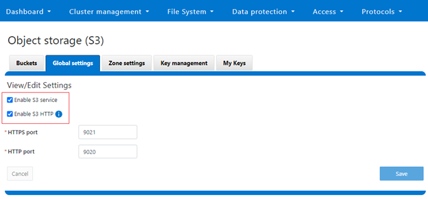
Note that, while the OneFS S3 service uses HTTP, it is considered as a tier-1 protocol, and as such is managed via its own ‘isi s3’ CLI command set and corresponding WebUI area. For example, the following CLI command will force the cluster to only accept encrypted HTTPS/SSL traffic on TCP port 9999 (rather than the default TCP port 9021):

# isi s3 settings global modify --https-only 1 –https-port 9921

# isi s3 settings global view

         HTTP Port: 9020

        HTTPS Port: 9999

        HTTPS only: Yes

S3 Service Enabled: Yes

Additionally, the S3 service can be disabled entirely with the following CLI syntax:

# isi services s3 disable

The service 's3' has been disabled.

Or from the WebUI under Protocols > S3 > Global settings:


OneFS Additional Security Hardening – Part 3

As mentioned in previous articles in this series, applying a hardening profile is one of multiple tasks that are required in order to configure a STIG-compliant PowerScale cluster. These include:

Component Tasks
Audit Configure remote syslog servers for auditing.
Authentication Configure secure auth provider, SecurityAdmin account, and default restricted shell.
CELOG Create event channel for security officers and system admin to monitor /root and /var partition usage, audit service, security verification, and account creation.
MFA & SSO Enable and configure multi-factor authentication and single sign-on.
NTP Configure secure NTP servers with SHA256 keys.
SMB Configure SMB global settings and defaults.

Enable SMB encryption on shares.

SNMP Enable SNMP and configure SNMPv3 settings.
SyncIQ Configure SyncIQ to use CA certificates so both the source and target clusters (primary and secondary DSCs) have both Server Authentication and Client Authentication set in their Extended Key Usages fields.

In this final article in the series, we’ll cover the security configuration details for SyncIQ replication using the OneFS CLI.

SyncIQ Setup

SyncIQ supports over-the-wire, end-to-end encryption for data replication, protecting and securing in-flight data between clusters. A global setting enforces encryption on all incoming and outgoing SyncIQ policies.

  1. First, on the source cluster, which is also the primary DSC (Digital Signature Certificate), add the CA (Certificate Authority) certificate(s) to certificate store.
# isi certificate authority import [ca certificate path]

Where:

Item Description
[ca certificate path] The path to the CA certificate file.

Note that SyncIQ certificates for both the source and target clusters (aka primary and secondary DSC respectively) must have both ‘Server Authentication’ and ‘Client Authentication’ set in their ‘Extended Key Usages’ fields.

Repeat as necessary, and include root and intermediate CA certificates for both the source and target, plus the OCSP (Online Certificate Status Protocol) issuer:

  • source cluster
  • target cluster
  • OCSP issuer

To prevent unauthorized access to the private key/certificate, ensure the certificate and private key files are deleted/removed once all necessary import steps have been successfully completed.


  1. Next, on the source cluster (primary DSC), add the source cluster certificate to the SyncIQ server certificate store. This can be accomplished with the following CLI syntax:
# isi sync certificates server import [source certificate path]

Where:

Item Description
[source certificate path] The path to the source certificate file (in PEM or DER format).
[source certificate key path] The path to the source certificate private key file.

Once again, to prevent unauthorized access to the private key/certificate, remove the certificate and private key files once import has been completed successfully.


  1. On the source cluster (primary DSC), set the cluster certificate to the certificate imported above.

Find certificate ID:

# isi certificate server list -v

Then configure cluster certificate ID:

# isi sync settings modify --cluster_certificate_id [certificate_id]

Where:

Item Description
[certificate id] The ID of the cluster certificate.


  1. On the source cluster (primary DSC) add the target cluster’s (secondary DSC) certificate as a peer certificate.
# isi sync certificates peer import [target certificate path]
Item Description
[target certificate path] The path to the target cluster/secondary DSC certificate file..

To prevent unauthorized access to the private key/certificate, remove certificate and private key files once done with all necessary import steps.


  1. On the source cluster (primary DSC) configure the global Open Certificate Status Protocol (OCSP) ID and address settings.
# isi sync settings modify

 --ocsp-issuer-certificate-id=[ocsp issuer certificate id]

 --ocsp-address=[OCSP server URI]

Where:

Item Description
[ocsp issuer certificate id] The ID of the certificate as registered in the PowerScale certificate manager.
[OCSP server URI] The URI of the OCSP responder.

To find the OCSP issuer certificate ID:

# isi certificate authority list -v

This assumes that the OCSP issuer certificate file has already been successfully imported into the PowerScale certificate manager.


  1. On the target cluster (secondary DSC), add the CA certificate(s) to the certificate store.
# isi certificate authority import [ca certificate path]

Where:

Item Description
[ca certificate path] The path to the CA certificate file.

Repeat as necessary, including the root and intermediate CA certificates for:

  • source cluster
  • target cluster
  • OCSP issuer

To prevent unauthorized access to the private key/certificate, remove certificate and private key files once done with all necessary import steps.

On the target cluster (secondary DSC), add the target cluster certificate to the SyncIQ server certificate store.

# isi sync certificates server import [target certificate path]

Where:

Item Description
[target certificate path] The path to the target certificate file (in PEM or DER format).
[target certificate key path] The path to the target certificate private key file.

To prevent unauthorized access to the private key/certificate, remove the certificate and private key files once done with all necessary import steps.


  1. On the target cluster (secondary DSC), set the cluster certificate to the certificate imported above.

First, retrieve the certificate ID:

# isi certificate server list -v

Next, configure the cluster certificate ID:

# isi sync settings modify --cluster_certificate_id [certificate_id]

Where:

Item Description
[certificate id] The ID of the cluster certificate


  1. On the target cluster (secondary DSC), add the source cluster’s (primary DSC) certificate as a peer certificate.
# isi sync certificates peer import [source certificate path]

Where:

Item Description
[source certificate path] The path to the source cluster/secondary DSC certificate file.

To prevent unauthorized access to the private key/certificate, remove certificate and private key files once done with all necessary import steps.

On the target cluster (secondary DSC), configure the  global Open Certificate Status Protocol (OCSP) settings.

# isi sync settings modify

 --ocsp-issuer-certificate-id=[ocsp issuer certificate id]

 --ocsp-address=[OCSP server URI]

Where:

Item Description
[ocsp issuer certificate id] The ID of the certificate as registered in the PowerScale certificate manager.
[OCSP server URI] The URI of the OCSP responder.

To find the OCSP issuer certificate ID:

# isi certificate authority list -v

This assumes that the OCSP issuer certificate file has already been imported into the PowerScale certificate manager.

  1. Finally, for any pre-existing policies, configure the following OCSP settings on the source cluster (primary DSC).
# isi sync policies modify [policy name]

 --ocsp-issuer-certificate-id=[ocsp issuer certificate id]

 --ocsp-address=[OCSP server URI]

Where:

Item Description
[ocsp issuer certificate id] The ID of the certificate as registered in the PowerScale certificate manager.

To find the OCSP issuer certificate ID:

# isi certificate authority list -v

At this point, the SyncIQ certificate configuration work should be complete.

OneFS Additional Security Hardening – Part 2

As mentioned in previous articles in this series, applying a hardening profile is one of multiple tasks that are required in order to configure a STIG-compliant PowerScale cluster. These include:

Component Tasks
Audit Configure remote syslog servers for auditing.
Authentication Configure secure auth provider, SecurityAdmin account, and default restricted shell.
CELOG Create event channel for security officers and system admin to monitor /root and /var partition usage, audit service, security verification, and account creation.
MFA & SSO Enable and configure multi-factor authentication and single sign-on.
NTP Configure secure NTP servers with SHA256 keys.
SMB Configure SMB global settings and defaults.

Enable SMB encryption on shares.

SNMP Enable SNMP and configure SNMPv3 settings.
SyncIQ Configure SyncIQ to use CA certificates so both the source and target clusters (primary and secondary DSCs) have both Server Authentication and Client Authentication set in their Extended Key Usages fields.

In this article, we’ll cover the specific configuration requirements and details of the NTP, SMB, SNMP components using the OneFS CLI.

NTP Setup

  1. When implementing a secure configuration for the OneFS NTP service, create an NTP key file and populate it with NTP server key hashes.

To add secure NTP servers to the OneFS configuration, first create an NTP keys file. This can be accomplished via the following CLI syntax:

# echo "[key index] sha256 [SHA hash]" > [keyfile]

Where:

Item Description
[key index] The index (increasing from 1) of the key hash.
[SHA hash] The SHA256 hash identifying the NTP server.
[keyfile] The path to the NTP key file.

Append as many additional key entries as are necessary. The ntp.keys(5) man page provides detailed information on the NTP key file format.

  1. Next, configure OneFS to use this NTP key file.
# isi ntp settings modify --key-file /ifs/ntp.keys
  1. The following CLI syntax can be used to configure NTP servers.
# isi ntp servers create [server hostname/IP] --key [key index]

Where:

Item Description
[server hostname/IP] The fully qualified domain name (FQDN) or IP address of the NTP server.
[key index] The key used by this particular server in the NTP keys file configured above..

Note that STIG requirements explicitly state that more than one (1) NTP server is required for compliance.

SMB setup

  1. Deploying SMB in a hardened environment typically involves enabling SMB3 encryption, security signatures, and disabling unencrypted access to shares. To accomplish this, first configure the global settings and defaults as follows.
# isi smb settings global modify --support-smb3-encryption true
 --enable-security-signatures true --require-security-signatures true
 --reject-unencrypted-access true


# isi_gconfig registry.Services.lwio.Parameters.Drivers.srv.SupportSmb1=0


# isi_gconfig registry.Services.lwio.Parameters.Drivers.rdr.Smb1Enabled=0
  1. Next, update the per-share SMB settings to enable SMB encryption.
# isi smb shares modify [share_name] --smb3-encryption-enabled true

SNMP Setup

  1. The following CLI command can be used to enable the OneFS SNMP v3 service and configure its settings and password.
# isi snmp settings modify --service=true --snmp-v3-access=true --snmp-v3-password=[password]

In the next and final article in this series, we’ll focus on the remaining topic in the list:

Namely secure SyncIQ configuration.

OneFS Additional Security Hardening – Part 1

When configuring security hardening on OneFS 9.5 or later, one thing to note is that, even with the STIG profile activated, not all the rules are automatically marked as ‘applied’. Specifically:

# isi hardening report view STIG | grep “Not Applied”

check_stig_celog_alerts                        Cluster   Not Applied Military Unique Deployment Guide manually configured CELOG settings.

check_synciq_default_ocsp_settings             Cluster   Not Applied /sync/settings/:cluster_certificate_id

check_synciq_policy_ocsp_settings              Cluster   Not Applied /sync/policies/:ocsp_issuer_certificate_id

check_multiple_ntp_servers_configured          Cluster   Not Applied /protocols/ntp/servers:total

set_auth_webui_sso_mfa_idp                     Cluster   Not Applied auth/providers/saml-services/idps/System

set_auth_webui_sso_mfa_sp_host                 Cluster   Not Applied auth/providers/saml-services/sp?zone=System:hostname

Applying a hardening profile is one of multiple tasks that are required in order to configure a STIG-compliant PowerScale cluster. These include:

Component Tasks
Audit Configure remote syslog servers for auditing.
Authentication Configure secure auth provider, SecurityAdmin account, and default restricted shell.
CELOG Create event channel for security officers and system admin to monitor /root and /var partition usage, audit service, security verification, and account creation.
MFA & SSO Enable and configure multi-factor authentication and single sign-on.
NTP Configure secure NTP servers with SHA256 keys.
SMB Configure SMB global settings and defaults.

Enable SMB encryption on shares.

SNMP Enable SNMP and configure SNMPv3 settings.
SyncIQ Configure SyncIQ to use CA certificates so both the source and target clusters (primary and secondary DSCs) have both Server Authentication and Client Authentication set in their Extended Key Usages fields.

Over the course of the next two blog articles, we’ll cover the specific configuration requirements and details of each of these components via the OneFS CLI.

In this article, we’ll focus on the following tasks:

Audit Setup

  1. To set up secure auditing, first configure the remote syslog server(s). Note that, while the configuration differentiates between configuration, protocol, and system auditing, these can be sent to the same central syslog server(s). When complete, these syslog servers can be added to the OneFS audit configuration via the following CLI syntax:
# isi audit settings global modify --config-syslog-servers=[server FQDN/IP] --protocol-syslog-servers=[server FQDN/IP] --system-syslog-servers=[server FQDN/IP]
  1. Also consider adding the cluster certificate to the audit settings for mutual Transport Layer Security (TLS) authentication.
# isi audit certificates syslog import [certificate_path] [key_path]

To prevent unauthorized access to the private key/certificate, the recommendation is to remove certificate and private key files once the necessary import steps have been completed.

Authentication Setup

  1. Set the default shell for any new users created in the Local Provider.
# isi auth local modify System --login-shell=/usr/local/restricted_shell/bin/restricted_shell.py
  1. Next, configure the remote authentication provider. This could be Kerberos, LDAP, or Active Directory. For more information, see the OneFS 9.5 CLI Administration Guide.

Note that all Active Directory users must have an e-mail address configured for them for use with ADFS multi-factor authentication (MFA).

Every Active Directory user must have a home directory created on the cluster, containing the correct public key in ~/.ssh/authorized_keys for the certificate presented by SSH clients (SecureCRT, PuTTY-CAC, etc).

If using Active Directory, the recommendation is to enable LDAP encryption, commonly referred to as ‘LDAP sign and seal’. For example:

# isi auth ads modify [provider-name] --ldap-sign-and-seal true

Additionally, the ‘machine password lifespan’ should be configured to a value of 60 days or less:

# isi auth ads modify [provider-name] --machine-password-lifespan=60D

Where [provider-name] is the name of the chosen Active Directory provider.

  1. Finally, identify a remote-authenticated user and assign them administrative privileges.
# isi auth roles modify SecurityAdmin --add-user [username]

# isi auth roles modify SystemAdmin --add-user [username]

Where [username] is the name of the chosen administrative user.

CELOG Setup

  1. For CELOG security setup, create and event channel for the required ISSO/SA alerts and configure appropriate event thresholds.

The following events need to send alerts on a channel monitored by an organization’s Information Systems Security Officers (ISSOs) or System Administrators (SAs):

Event ID Event
100010001 The /var partition is near capacity.
100010002 The /var/crash partition is near capacity.
100010003 The root partition is near capacity.
400160002 Audit system cannot provide service.
400160005 Audit daemon failed to persist events.
400200001 Security verification check failed.
400200002 Security verification successfully ran.
400260000 User account(s) created/updated/removed.

The event channel can be created as follows:

# isi event channels create [channel name] [type] [options]

Next, the thresholds for the above event IDs can be set:

# isi event thresholds modify 100010001 --info 74 --warn 75

# isi event thresholds modify 100010002 --warn 75

# isi event thresholds modify 100010003 --warn 75

# isi event alerts create [event name 1] NEW [channel name]

 --eventgroup 100010001  --eventgroup 100010002 --eventgroup 100010003

 --eventgroup 400160002 --eventgroup 400160005 --eventgroup 400200001

 --eventgroup 400200002 --eventgroup 400260000


# isi event alerts create [event name 2] SEVERITY_INCREASE [channel name]

 --eventgroup 100010001 --eventgroup 100010002 --eventgroup 100010003

 --eventgroup 400160002 --eventgroup 400160005 --eventgroup 400200001

 --eventgroup 400200002 --eventgroup 400260000

Where:

Item Description
[channel name] The name of the newly configured event channel.
[event name 1] and [event name 2] The names of the events that will trigger alerts when a new event occurs or when an event increases in severity, respectively.
Multi-Factor Authentication (MFA)/Single Sign-On (SSO) Setup

  1. First, configure the SSO service provider. This can be achieved as follows:
# isi auth sso sp modify --hostname=[node IP or cluster FQDN]

Where [node IP or cluster FQDN] is the IP address of a node in the PowerScale cluster or the fully qualified domain name (FQDN) of the PowerScale cluster.

  1. Next, configure the Identity Provider (IdP) as follows:
# isi auth sso idps create [name] [options]
  1. Enable MFA/SSO.
# isi auth sso settings modify --sso-enabled=true

At this point, we’ve covered the configuration and setup of the first four components in the list.

In the next article in this series, we’ll focus on the remaining topics:

Namely secure NTP, SMB, SNMP, and SyncIQ configuration.