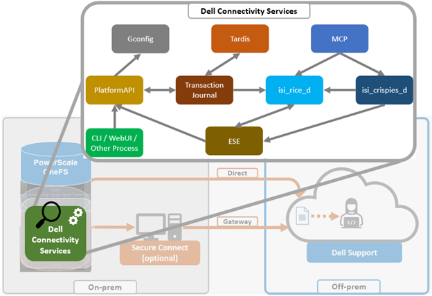
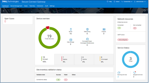
In OneFS 9.10, several OneFS components leverage Dell Technologies Connectivity Services (DTCS) as their secure off-cluster data retrieval and communication channel. These include:
| Component | Details |
| Events and Alerts | DTCS can send CELOG events and attachments via ESE to CLM. |
| Diagnostics | Logfile gathers can be uploaded to Dell via DTCS. |
| License activation | License activation uses DTCS for the ‘isi license activation start’ CLI cmd |
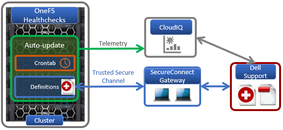
| Telemetry | Telemetry is sent through DTCS to CloudIQ for analytics |
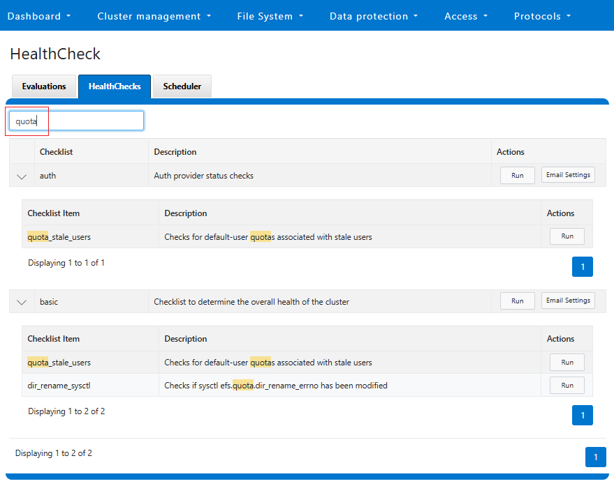
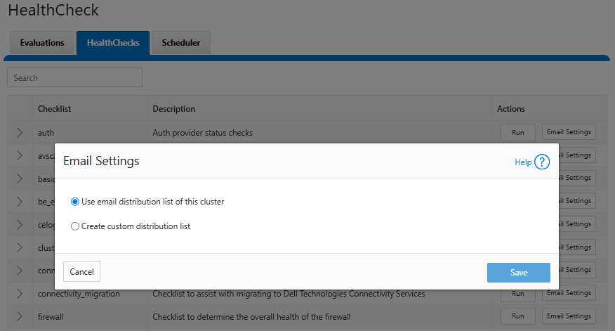
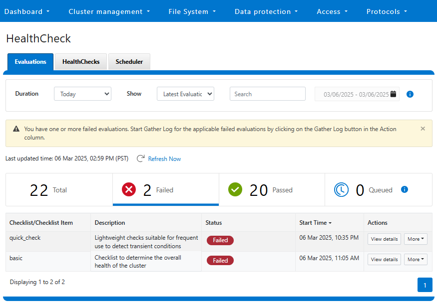
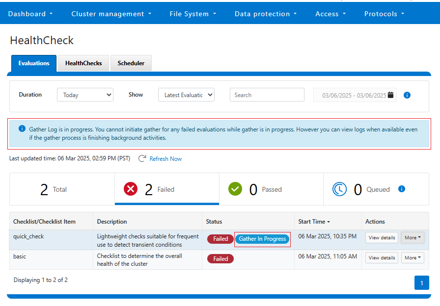
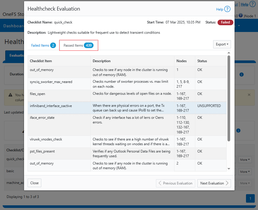
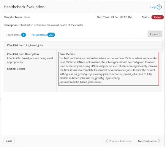
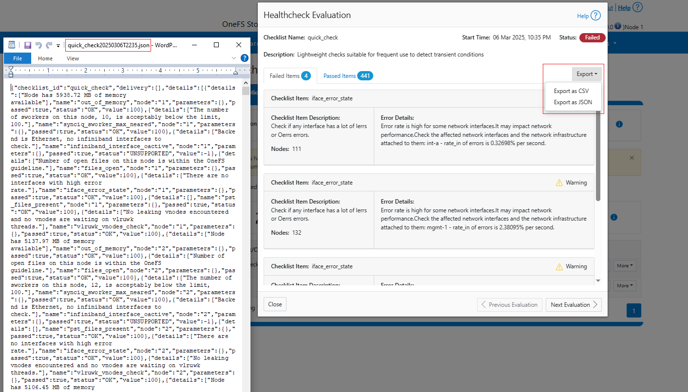
| Health check | Health check definition downloads leverage DTCS |
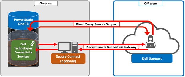
| Remote Support | Remote Support uses DTCS along with Connectivity Hub |
For existing clusters, DTCS supports the same basic workflows as its predecessors, ESRS and SupportAssist, so the transition from old to new is generally pretty seamless.
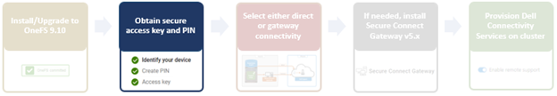
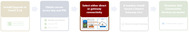
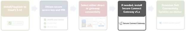
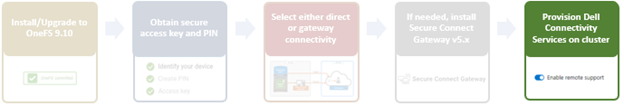
As such, the overall process for enabling DTCS in OneFS is as follows:
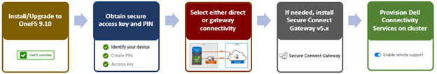
- Upgrade the cluster to OneFS 9.10.
- Obtain the secure access key and PIN.
- Select either direct connectivity or gateway connectivity.
- If using gateway connectivity, install Secure Connect Gateway (v5.0 or later).
- Provision DTCS on the cluster.
We’ll go through each of the configuration steps above in order:
- Install or upgrade to OneFS 9.10.
First, the cluster must be running OneFS 9.10 in order to configure DTCS.
There are some additional considerations and caveats to bear in mind when upgrading to OneFS 9.10 and planning on enabling DTCS. These include the following:
- DTCS is disabled when STIG Hardening applied to cluster
- Using DTCS on a hardened cluster is not supported
- Clusters with the OneFS network firewall enabled (‘isi network firewall settings’) may need to allow outbound traffic on ports 443 and 8443, plus 9443 if gateway (SCG) connectivity is configured.
- DTCS is supported on a cluster that’s running in Compliance mode
- If the cluster already has SupportAssist configured and running, the conversion to DTCS will occur automatically.
- If upgrading from an earlier release on a cluster not running SupportAssist, the OneFS 9.10 upgrade to must be committed before DTCS can be provisioned.
Also, ensure that the user account that will be used to enable DTCS belongs to a role with the ‘ISI_PRIV_REMOTE_SUPPORT’ read and write privilege. For example:
# isi auth privileges | grep REMOTE

ISI_PRIV_REMOTE_SUPPORT                        Configure remote support
For example, the ‘ese’ user account below:
# isi auth roles view ConnectivityServicesRole

Name: ConnectivityServicesRole

Description: -

Members: ese

Privileges

ID: ISI_PRIV_LOGIN_PAPI

Permission: r


ID: ISI_PRIV_REMOTE_SUPPORT

Permission: w
- Obtaining secure access key and PIN.
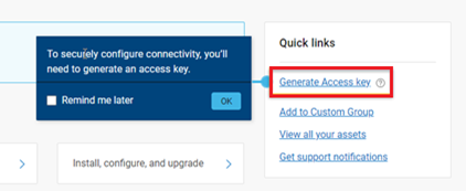
An access key and pin are required in order to provision DTCS, and these secure keys are held in Key manager under the RICE domain. This access key and pin can be obtained from the Dell Support site:
In the Quick link navigation bar, select the ‘Generate Access key’ link:
On the following page, select the appropriate button:
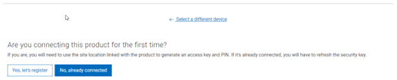
The credentials required to obtain an access key and pin vary depending on prior cluster configuration. Sites that have previously provisioned ESRS will need their OneFS Software ID (SWID) to obtain their access key and pin.
The ‘isi license list’ CLI command can be used to determine a cluster’s SWID. For example:
# isi license list | grep "OneFS Software ID"

OneFS Software ID: ELMISL999CKKD
However, customers with new clusters and/or have not previously provisioned ESRS or SupportAssist will require their Site ID in order to obtain the access key and pin.
Note that any new cluster hardware shipping after January 2023 will already have a built-in key, so this key can be used in place of the Site ID above.
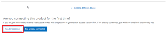
For example, if this is the first time registering this cluster and it does not have a built-in key, select ‘Yes, let’s register’:
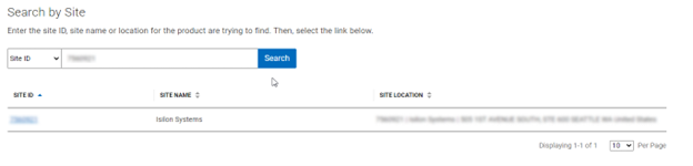
Enter the Site ID, site name, and location information for the cluster:
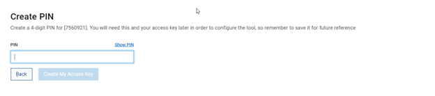
Choose a 4-digit PIN and save it for future reference. After that click the ‘Create My Access Key’ button:
Next, the access key is generated.
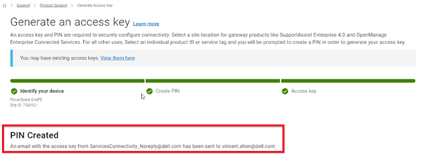
An automated email is sent from the Dell Services Connectivity Team containing the pertinent key info, including:
- Access Key
- Product ID
- Site ID/UCID
- Expiration Date
For example:
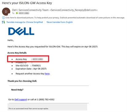
Note that this access key is valid for one week, after which it automatically expires.
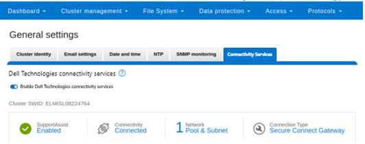
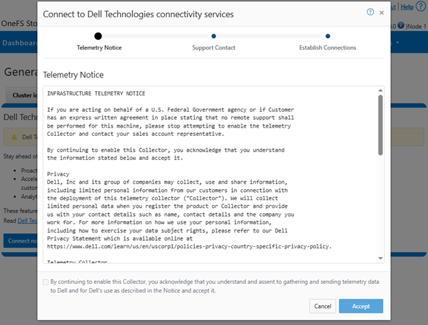
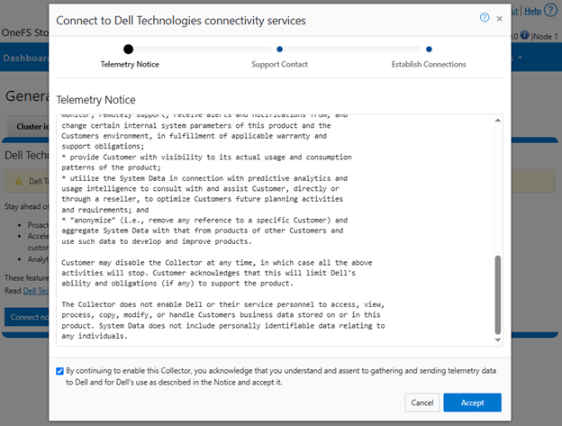
Next, in the cluster’s WebUI, navigate back to Cluster management > General settings > Connectivity Services and complete the EULA:
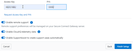
Next, enter the access key and PIN information in the appropriate fields. Finally, click the ‘Finish Setup’ button to complete the DTCS provisioning process:
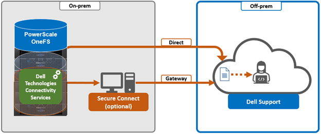
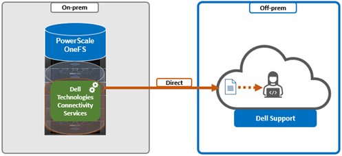
- Direct or gateway topology decision.
A topology decision will need to be made between implementing either direct connectivity or gateway connectivity, depending on the needs of the environment:
- Direct Connect:
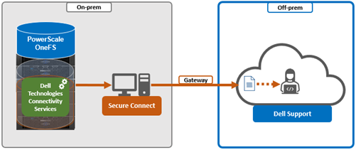
- Gateway Connect:
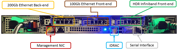
DTCS uses ports 443 and 8443 by default for bi-directional communication between the cluster and Connectivity Hub. As such, these ports will need to be open across any firewalls or packet filters between the cluster and the corporate network edge to allow connectivity to Dell Support.
Additionally, port 9443 is used for communicating with a gateway (SCG).
# grep -i esrs /etc/services

isi_esrs_d      9443/tcp  #EMC Secure Remote Support outbound alerts
- Optional Secure Connect Gateway installation.
This step is only required when deploying a Secure Connect gateway. If a direct connect topology is desired, go directly to step 5 below.
When configuring DTCS with the gateway connectivity option, Secure Connect Gateway v5.0 or later must be deployed within the data center.
Dell Secure Connect Gateway (SCG) is available for Linux, Windows, Hyper-V, and VMware environments, and as of writing, the latest version is 5.28.00. The installation binaries can be downloaded from: https://www.dell.com/support/home/en-us/product-support/product/secure-connect-gateway/drivers
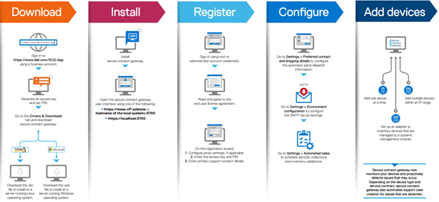
The procedure to download SCG is as follows:
- Sign in to https://www.dell.com/support/product-details/en-us/product/secure-connect-gateway-app-edition. The Secure Connect Gateway – Application Edition page is displayed. If you have issues signing in using your business account or unable to access the page even after signing in, contact Dell Administrative Support.
- In the Quick links section, click Generate Access key.
- On the Generate Access Key page, perform the following steps:
- Select a site ID, site name, or site location.
- Enter a four-digit PIN and click Generate key. An access key is generated and sent to your email address. NOTE: The access key and PIN must be used within seven days and cannot be used to register multiple instances of secure connect gateway.
- Click Done.
- On the Secure Connect Gateway – Application Edition page, click the Drivers & Downloads tab.
- Search and select the required version.
- In the ACTION column, click Download.
The following steps are required in order to setup SCG:
Pertinent resources for configuring and running SCG include:
SCP Support Matrix, for supported devices, protocols, firmware versions, and operating systems.
Another useful source of SCG installation, configuration, and troubleshooting information is the Dell support forum: https://www.dell.com/community/Secure-Connect-Gateway/bd-p/SCG
- Provisioning DTCS on the cluster.
At this point, the off-cluster pre-staging work should be complete.
In the next article in this series, we turn our attention to the DTCS provisioning process on the cluster itself (step 5).