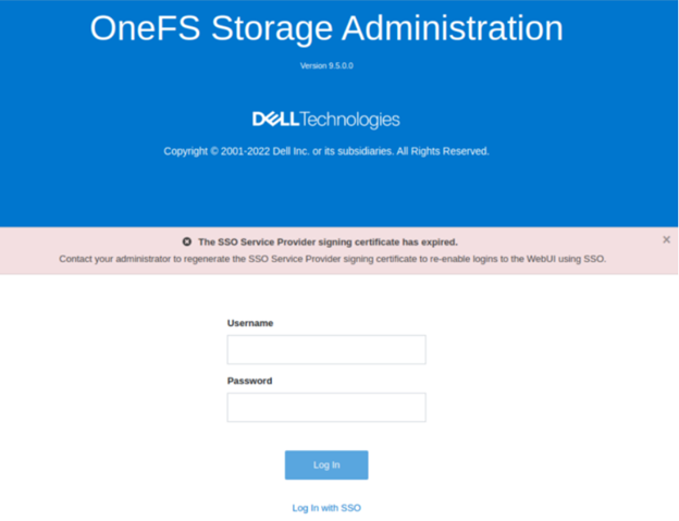
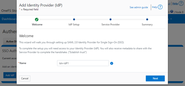
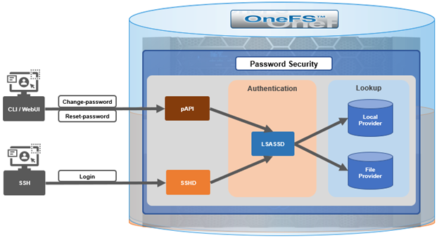
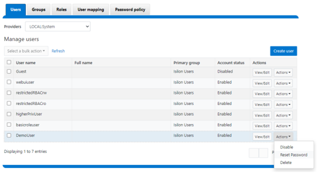
When using either the OneFS WebUI or platform API (pAPI), all communication sessions are encrypted using SSL (Secure Sockets Layer), also known as Transport Layer Security (TLS). In this series, we’ll take a look at how to replace or renew the SSL certificate for the OneFS WebUI.
SSL requires a certificate that serves two principal function: It grants permissions to use encrypted communication via Public Key Infrastructure, and also authenticates the identity of the certificate’s holder.
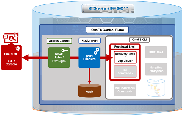
Architecturally, SSL comprises four fundamental components:
| SSL Component | Description |
| Alert | Reports issues. |
| Change cipher spec | Implements negotiated crypto parameters. |
| Handshake | Negotiates crypto parameters for SSL session. Can be used for many SSL/TCP connections. |
| Record | Provides encryption and MAC. |
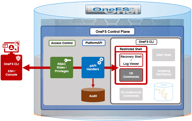
These sit in the stack as follows:
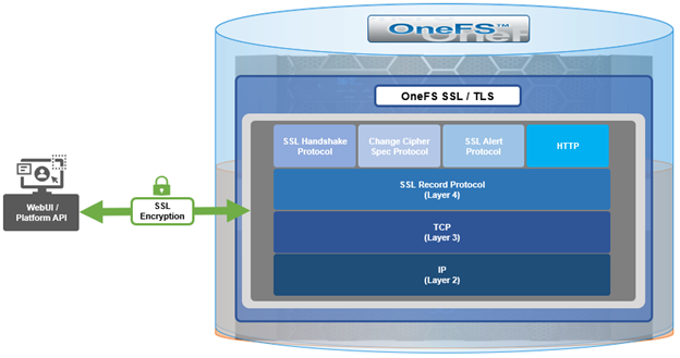
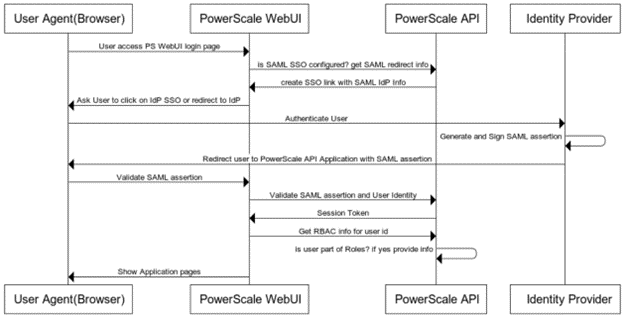
The basic handshake process begins with a client requesting an HTTPS WebUI session to the cluster. OneFS then returns the SSL certificate and public key. The client creates a session key, encrypted with the public key it’s received from OneFS. At this point, the client only knows the session key. The client now sends its encrypted session key to the cluster, which decrypts it with the private key. Now, both the client and OneFS know the session key. So, finally the session, encrypted via symmetric session key, can be established. OneFS automatically defaults to the best supported version of SSL, based on the client request.
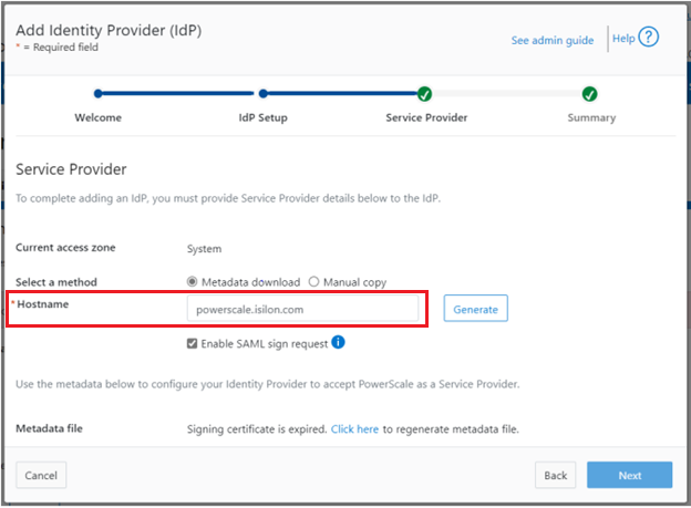
A PowerScale cluster initially contains a self-signed certificate, which can be used as-is, or replaced with a third-party certificate authority (CA)-issued certificate. If the self-signed certificate is used, upon expiry, it must be replaced with either a third-party (public or private) CA-issued certificate or another self-signed certificate that is generated on the cluster. The following are the default locations for the server.crt and server.key files.
| File | Location |
| SSL certificate | /usr/local/apache2/conf/ssl.crt/server.crt |
| SSL certificate key | /usr/local/apache2/conf/ssl.key/server.key |
The ‘isi certificate settings view’ CLI command displays all of the certificate-related configuration options. For example:
# isi certificate settings view

         Certificate Monitor Enabled: Yes

Certificate Pre Expiration Threshold: 4W2D

           Default HTTPS Certificate

                                      ID: default

                                 Subject: C=US, ST=Washington, L=Seattle, O="Isilon", OU=Isilon, CN=Dell, emailAddress=tme@isilon.com

                                  Status: valid
The above ‘certificate monitor enabled’ and ‘certificate pre expiration threshold’ config options govern a nightly cron job, which monitors the expiration of each managed certificate and fires a CELOG alert if a certificate is set to expire within the configured threshold. Note that the default expiration is 30 days (4W2D, which represents 4 weeks plus 2 days). The ‘ID: default’ config option indicates that this certificate is the default TLS certificate.
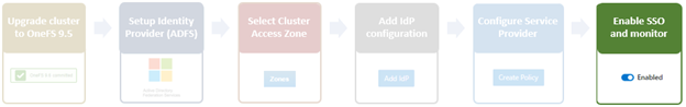
The basic certificate renewal or creation flow is as follows:
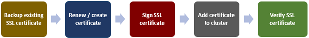
The steps below include options to complete a self-signed certificate replacement or renewal, or to request an SSL replacement or renewal from a Certificate Authority (CA).
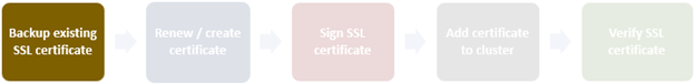
Backing up the existing SSL certificate
The first task is to obtain the list of certificates by running the following CLI command, and identify the appropriate one to renew:
# isi certificate server list

ID      Name    Status  Expires

-------------------------------------------

eb0703b default valid   2025-10-11T10:45:52

-------------------------------------------
It’s always a prudent practice to save a backup of the original certificate and key. This can be easily accomplished via the following CLI commands, which, in this case, create the directory ‘/ifs/data/ssl_bkup’ directory, set the perms to root-only access, and copy the original key and certificate to it:
# mkdir -p /ifs/data/ssl_bkup

# chmod 700 /ifs/data/ssl_bkup

# cp /usr/local/apache24/conf/ssl.crt/server.crt /ifs/data/ssl_bkup

# cp /usr/local/apache24/conf/ssl.key/server.key /ifs/data/ssl_bkup

# cd !$

cd /ifs/data/ssl_bkup

# ls

server.crt      server.key
Renewing or creating a certificate
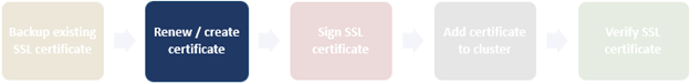
The next step in the process involves either the renewal of an existing certificate or creation of a certificate from scratch. In either case, first, create a temporary directory, for example /ifs/tmp:
# mkdir /ifs/tmp; cd /ifs/tmp
a) Renew an existing self-signed Certificate.
The following syntax creates a renewal certificate that is based on the existing ssl.key. The value of the ‘-days’ parameter can be adjusted to generate a certificate with the desired expiration date. For example, the following command will create a one-year certificate.
# cp /usr/local/apache2/conf/ssl.key/server.key ./ ; openssl req -new -days 365 -nodes -x509 -key server.key -out server.crt
Answer the system prompts to complete the self-signed SSL certificate generation process, entering the pertinent information location and contact information. For example:
Country Name (2 letter code) [AU]:US
State or Province Name (full name) [Some-State]:Washington
Locality Name (eg, city) []:Seattle
Organization Name (eg, company) [Internet Widgits Pty Ltd]:Isilon
Organizational Unit Name (eg, section) []:TME
Common Name (e.g. server FQDN or YOUR name) []:isilon.com
Email Address []:tme@isilon.com
When all the information has been successfully entered, the server.csr and server.key files will be generated under the /ifs/tmp directory.
Optionally, the attributes and integrity of the certificate can be verified with the following syntax:
# openssl x509 -text -noout -in server.crt
Next, proceed directly to the ‘Add the certificate to the cluster’ steps in section 4 of this article.
b) Alternatively, a certificate and key can be generated from scratch, if preferred.
The following CLI command can be used to create an 2048-bit RSA private key:
# openssl genrsa -out server.key 2048

Generating RSA private key, 2048 bit long modulus

............+++++

...........................................................+++++

e is 65537 (0x10001)
Next, create a certificate signing request:
# openssl req -new -nodes -key server.key -out server.csr
For example:
# openssl req -new -nodes -key server.key -out server.csr -reqexts SAN -config <(cat /etc/ssl/openssl.cnf <(printf "[SAN]\nsubjectAltName=DNS:isilon.com"))

You are about to be asked to enter information that will be incorporated

into your certificate request.

What you are about to enter is what is called a Distinguished Name or a DN.

There are quite a few fields but you can leave some blank

For some fields there will be a default value,

If you enter '.', the field will be left blank.

-----

Country Name (2 letter code) [AU]:US

State or Province Name (full name) [Some-State]:WA

Locality Name (eg, city) []:Seattle

Organization Name (eg, company) [Internet Widgits Pty Ltd]:Isilon

Organizational Unit Name (eg, section) []:TME

Common Name (e.g. server FQDN or YOUR name) []:h7001

Email Address []:tme@isilon.com

Please enter the following 'extra' attributes

to be sent with your certificate request

A challenge password []:1234

An optional company name []:

#
Answer the system prompts to complete the self-signed SSL certificate generation process, entering the pertinent information location and contact information. Additionally, a ‘challenge password’ with a minimum of 4-bytes in length will need to be selected and entered.
As prompted, enter the information to be incorporated into the certificate request. When completed, the server.csr and server.key files will appear in the /ifs/tmp directory.
If desired, a CSR file for a Certificate Authority which includes Subject-Alternative-Names (SAN) can be generated. For example, additional host name entries can be added by using a comma (IE. DNS:isilon.com,DNS:www.isilon.com).
In the next article, we’ll look at the certificate singing, addition, and verification steps of the process.