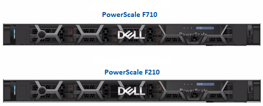
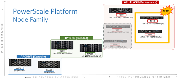
In this article, we’ll take a quick peek at the new PowerScale F210 hardware platform that was released last week. Here’s where this new node sits in the current hardware hierarchy:
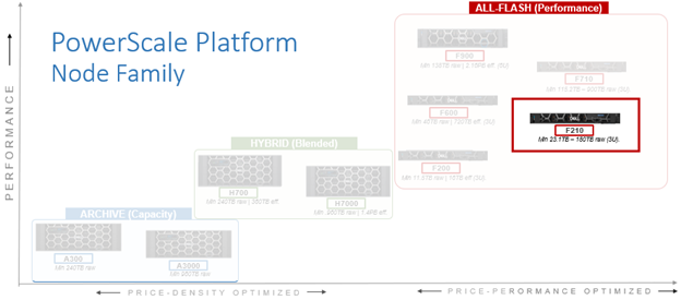
The PowerScale F210 is an entry level, performant, all-flash platform that utilizes NVMe SSDs and a single-socket CPU 1U PowerEdge platform with 128GB of memory per node. The ideal use cases for the F210 include high performance workflows, such as M&E, EDA, AI/ML, and other HPC applications.
An F210 cluster can comprise between 3 and 252 nodes, each of which contains four 2.5” drive bays populated with a choice of 1.92TB, 3.84TB, 7,68TB TLC, or 15.36TB QLC enterprise NVMe SSDs. Inline data reduction, which incorporates compression, dedupe, and single instancing, is also included as standard and enabled by default to further increase the effective capacity.
The F210 is based on the 1U R660 PowerEdge server platform, with a single socket Intel Sapphire Rapids CPU.
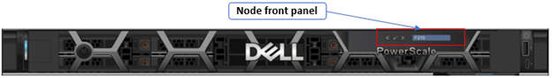
The node’s front panel has limited functionality compared to older platform generations and simply allows the user to join a node to a cluster and display the node name once the node has successfully joined.
An F210 node’s serial number can be found either by viewing /etc/isilon_serial_number or via the following CLI command syntax. For example:
# isi_hw_status | grep SerNo
  SerNo: HVR3FZ3
The serial number reported by OneFS will match that of the service tag attached to the physical hardware and the /etc/isilon_system_config file will report the appropriate node type. For example:
# cat /etc/isilon_system_config
PowerScale F210
Under the hood, the F210’s core hardware specifications are as follows:
| Attribute | F210 Spec |
| Chassis | 1RU Dell PowerEdge R660 |
| CPU | Single socket, 12 core Intel Sapphire Rapids 4410Y @2GHz |
| Memory | 128GB Dual rank DDR5 RDIMMS (8 x 16GB) |
| Journal | 1 x 32GB SDPM |
| Front-end network | 2 x 100GbE or 25GbE |
| Back-end network | 2 x 100GbE or 25GbE |
| NVMe SSD drives | 4 |
The node hardware attributes can be gleaned from OneFS by running the ‘isi_hw_status’ CLI command. For example:
f2101-1# isi_hw_status -c

  HWGen: PSI

Chassis: POWEREDGE (Dell PowerEdge)

    CPU: GenuineIntel (2.00GHz, stepping 0x000806f8)

   PROC: Single-proc, 12-HT-core

    RAM: 102488403968 Bytes

   Mobo: 0MK29P (PowerScale F210)

  NVRam: NVDIMM (NVDIMM) (8192MB card) (size 8589934592B)

 DskCtl: NONE (No disk controller) (0 ports)

 DskExp: None (No disk expander)

PwrSupl: PS1 (type=AC, fw=00.1B.53)

PwrSupl: PS2 (type=AC, fw=00.1B.53)
While the actual health of the CPU and power supplies can be quickly verified as follows:
# isi_hw_status -s

Power Supplies OK

Power Supply PS1 good

Power Supply PS2 good

CPU Operation (raw 0x881B0000)  = Normal
Additionally, the ‘-A’ flag (All) can also be used with ‘isi_hw-status’ to query a plethora of hardware and environmental information.
Node and drive firmware versions can also be checked with the ‘isi_firmware_tool’ utility. For example:
f2101-1# isi_firmware_tool --check

Ok

f2101-1# isi_firmware_tool --show

Thu Oct 26 11:42:32 2023 - Drive_Support_v1.46.tgz

Thu Oct 26 11:42:58 2023 - IsiFw_Package_v11.7qa1.tar
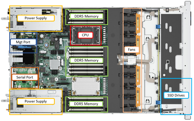
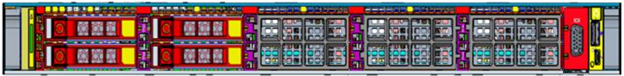
The internal layout of the F210 chassis with the risers removed is as follows:
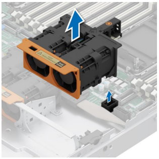
The cooling is primarily driven by four dual-fan modules, which can be easily accessed and replaced as follows:
Additionally, the power supplies also contain their own air flow apparatus, and can be easily replaced from the rear without opening the chassis.
For storage, each PowerScale F210 node contains four NVMe SSDs, which are currently available in the following capacities and drive styles:
| Standard drive capacity | SED-FIPS drive capacity | SED-non-FIPS drive capacity |
| 1.92 TB TLC | 1.92 TB TLC |
– |
| 3.84 TB TLC | 3.84 TB TLC |
– |
| 7.68 TB TLC | 7.68 TB TLC |
– |
| 15.36 TB QLC | Future availability | 15.36 TB QLC |
Note that a 15.36TB SED-FIPS drive option is planned for future release. Additionally, the 1.92TB drives in the F210 can also be short-stroke formatted for node compatibility with F200s containing 960GB SSD drives. More on this later in the article.
The F210’s NVMe SSDs populate the drive bays on the left front of the chassis, as illustrated in the following front view (with bezel removed):
Drive subsystem-wise, OneFS provides NVMe support across PCIe lanes, and the SSDs use the NVMe and NVD drivers. The NVD is a block device driver that exposes an NVMe namespace like a drive and is what most OneFS operations act upon, and each NVMe drive has a /dev/nvmeX, /dev/nvmeXnsX and /dev/nvdX device entry and the locations are displayed as ‘bays’. Details can be queried with OneFS CLI drive utilities such as ‘isi_radish’ and ‘isi_drivenum’. For example:
f2101-1# isi_drivenum
Bay 0   Unit 3      Lnum 0     Active      SN:BTAC2263000M15PHGN   /dev/nvd3
Bay 1   Unit 2      Lnum 2     Active      SN:BTAC226206VB15PHGN   /dev/nvd2
Bay 2   Unit 0      Lnum 1     Active      SN:BTAC226206R515PHGN   /dev/nvd0
Bay 3   Unit 1      Lnum 3     Active      SN:BTAC226207ER15PHGN   /dev/nvd1
Bay 4   Unit N/A    Lnum N/A   N/A         SN:N/A              N/A
Bay 5   Unit N/A    Lnum N/A   N/A         SN:N/A              N/A
Bay 6   Unit N/A    Lnum N/A   N/A         SN:N/A              N/A
Bay 7   Unit N/A    Lnum N/A   N/A         SN:N/A              N/A
Bay 8   Unit N/A    Lnum N/A   N/A         SN:N/A              N/A
Bay 9   Unit N/A    Lnum N/A   N/A         SN:N/A              N/A
As shown, the four NVMe drives occupy bays 0-3, with the remaining six bays unoccupied. These four drives and their corresponding PCI bus addresses can also be viewed via the following CLI command:
f2101-1# pciconf -l | grep nvme
nvme0@pci0:155:0:0:     class=0x010802 card=0x219c1028 chip=0x0b608086 rev=0x00 hdr=0x00
nvme1@pci0:156:0:0:     class=0x010802 card=0x219c1028 chip=0x0b608086 rev=0x00 hdr=0x00
nvme2@pci0:157:0:0:     class=0x010802 card=0x219c1028 chip=0x0b608086 rev=0x00 hdr=0x00
nvme3@pci0:158:0:0:     class=0x010802 card=0x219c1028 chip=0x0b608086 rev=0x00 hdr=0x00
Comprehensive details and telemetry for individual drive are available via the ‘isi_radish’ CLI command using their /dev/nvdX device entry. For example, for /dev/nvd0:
f2101-1# isi_radish -a /dev/nvd0
Drive log page ca: Intel Vendor Unique SMART Log
              Key                              Attribute                                         Field                                                 Value
============================== ========================================
(5.0) (4.0)=(171) (0.0)              Program Fail Count                 Normalized Value                                        100
(5.0) (4.0)=(171) (0.1)                                                 Raw Value                                               0
(5.0) (4.0)=(172) (0.0)              Erase Fail Count                   Normalized Value                                        100
(5.0) (4.0)=(172) (0.1)                                                 Raw Value                                               0
(5.0) (4.0)=(173) (2.0)              Wear Leveling Count                Normalized Value                                        100
(5.0) (4.0)=(173) (2.1)                                                 Min. Erase Cycle                                        2
(5.0) (4.0)=(173) (2.2)                                                 Max. Erase Cycle                                        14
(5.0) (4.0)=(173) (2.3)                                                Avg. Erase Cycle                                        5
(5.0) (4.0)=(184) (1.0)              End to End Error Detection Count   Raw Value                                               0
(5.0) (4.0)=(234) (3.0)              Thermal Throttle Status            Percentage                                              0
(5.0) (4.0)=(234) (3.1)                                                 Throttling event count                                  0
(5.0) (4.0)=(243) (1.0)              PLL Lock Loss Count                Raw Value                                               0
(5.0) (4.0)=(244) (1.0)              NAND sectors written divided by .. Raw Value                                               3281155
(5.0) (4.0)=(245) (1.0)              Host sectors written divided by .. Raw Value                                               1445498
(5.0) (4.0)=(246) (1.0)              System Area Life Remaining         Raw Value                                               0
Drive log page de: DellEMC Unique Log Page

              Key                              Attribute                                         Field                                                 Value
============================== ======================================== ======================================================= ==================================================
(6.0)                            DellEMC Unique Log Page                Log Page Revision                                       2
(6.1)                                                                   System Aread Percent Used                               0
(6.2)                                                                   Max Temperature Seen                                    48
(6.3)                                                                   Media Total Bytes Written                               110097292328960
(6.4)                                                                   Media Total Bytes Read                                  176548657233920
(6.5)                                                                   Host Total Bytes Read                                   164172138545152
(6.6)                                                                   Host Total Bytes Written                                48502864347136
(6.7)                                                                   NAND Min. Erase Count                                   2
(6.8)                                                                   NAND Avg. Erase Count                                   5
(6.9)                                                                   NAND Max. Erase Count                                   14
(6.10)                                                                  Media EOL PE Cycle Count                                3000
(6.11)                                                                  Device Raw Capacity                                     15872
(6.12)                                                                  Total User Capacity                                     15360
(6.13)                                                                  SSD Endurance                                           4294967295
(6.14)                                                                  Command Timeouts                                        18446744073709551615
(6.15)                                                                  Thermal Throttle Count                                  0
(6.16)                                                                 Thermal Throttle Status                                 0
(6.17)                                                                  Short Term Write Amplification                          192
(6.18)                                                                  Long Term Write Amplification                           226
(6.19)                                                                  Born on Date                                            06212022
(6.20)                                                                  Assert Count                                            0
(6.21)                                                                  Supplier firmware-visible hardware revision             5
(6.22)                                                                  Subsystem Host Read Commands                            340282366920938463463374607431768211455
(6.23)                                                                  Subsystem Busy Time                                     340282366920938463463374607431768211455
(6.24)                                                                  Deallocate Command Counter                              0
(6.25)                                                                  Data Units Deallocated Counter                          165599450
Log Sense data (Bay 2/nvd0 ) --
Supported log pages 0x1 0x2 0x3 0x4 0x5 0x6 0x80 0x81

SMART/Health Information Log
============================
Critical Warning State:         0x00
 Available spare:               0
 Temperature:                   0
 Device reliability:            0
 Read only:                     0
 Volatile memory backup:        0
Temperature:                    307 K, 33.85 C, 92.93 F
Available spare:                100
Available spare threshold:      10
Percentage used:                0
Data units (512,000 byte) read: 320648767
Data units written:             94732208
Host read commands:             3779434531
Host write commands:            1243274334
Controller busy time (minutes): 33
Power cycles:                   93
Power on hours:                 2718
Unsafe shutdowns:               33
Media errors:                   0
No. error info log entries:     0
Warning Temp Composite Time:    0
Error Temp Composite Time:      0
Temperature 1 Transition Count: 0
Temperature 2 Transition Count: 0
Total Time For Temperature 1:   0
Total Time For Temperature 2:   0

SMART status is threshold NOT exceeded (Bay 2/nvd0 )
NAND Write Amplification: 2.269913, (Bay 2/nvd0 )

Error Information Log
=====================
No error entries found
Bay 2/nvd0  is Dell Ent NVMe SED P5316 RI 15.36TB FW:1.2.0 SN:BTAC226206R515PHGN, 30001856512 blks

                Attr                          Value
=================================== =========================
NAND Bytes Written                  3281155
Host Bytes Written                  1445498

Drive Attributes: (Bay 2/nvd0 )
In contrast, the rear of the F710 chassis contains the power supplies, network, and management interfaces, which are laid out as follows:
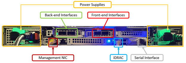
The F210 nodes are available in the following networking configurations, with a 25/100Gb ethernet back-end and 25/100Gb ethernet front-end:
| Front-end NIC | Back-end NIC | F210 NIC Support |
| 100GbE | 100GbE | Yes |
| 100GbE | 25GbE | No |
| 25GbE | 100GbE | Yes |
| 25GbE | 25GbE | Yes |
Note that there is currently no support for an F210 Infiniband backend in OneFS 9.7.
These NICs and their PCI bus addresses can be determined via the ’pciconf’ CLI command, as follows:
f2101-1# pciconf -l | grep mlx
mlx5_core0@pci0:23:0:0: class=0x020000 card=0x005815b3 chip=0x101d15b3 rev=0x00 hdr=0x00
mlx5_core1@pci0:23:0:1: class=0x020000 card=0x005815b3 chip=0x101d15b3 rev=0x00 hdr=0x00
mlx5_core2@pci0:111:0:0:        class=0x020000 card=0x005815b3 chip=0x101d15b3 rev=0x00 hdr=0x00
mlx5_core3@pci0:111:0:1:        class=0x020000 card=0x005815b3 chip=0x101d15b3 rev=0x00 hdr=0x00
Similarly, the NIC hardware details and drive firmware versions can be view as follows:
f2101-1# mlxfwmanager
Device #1:
----------
  Device Type:      ConnectX6DX
  Part Number:      0F6FXM_08P2T2_Ax
  Description:      Mellanox ConnectX-6 Dx Dual Port 100 GbE QSFP56 Network Adapter
  PSID:             DEL0000000027
  PCI Device Name:  pci0:23:0:0
  Base GUID:        a088c20300052a3c
  Base MAC:         a088c2052a3c
  Versions:         Current        Available
     FW             22.36.1010     N/A
     PXE            3.6.0901       N/A
     UEFI           14.29.0014     N/A
  Status:           No matching image found

Device #2:
----------
  Device Type:      ConnectX6DX
  Part Number:      0F6FXM_08P2T2_Ax
  Description:      Mellanox ConnectX-6 Dx Dual Port 100 GbE QSFP56 Network Adapter
  PSID:             DEL0000000027
  PCI Device Name:  pci0:111:0:0
  Base GUID:        a088c2030005194c
  Base MAC:         a088c205194c
  Versions:         Current        Available
     FW             22.36.1010     N/A
     PXE            3.6.0901       N/A
     UEFI           14.29.0014     N/A
  Status:           No matching image found
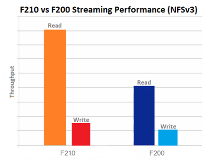
Performance-wise, the new F210 is a relative powerhouse compared to the F200. This is especially true for NFSv3 streaming reads, as can be seen below:
OneFS node compatibility provides the ability to have similar node types and generations within the same node pool. In OneFS 9.7, compatibility between the F210 nodes and the previous generation F200 platform is supported.
| Component | F200 | F210 |
| Platform | R640 | R660 |
| Drives | 4 x SAS SSD | 4 x NVMe SSD |
| CPU | Intel Xeon Silver 4210 (Cascade Lake) | Intel Xeon Silver 4410Y (Sapphire Rapids) |
| Memory | 96GB DDR4 | 96GB DDR5 |
This compatibility facilitates the addition of individual F210 nodes to an existing node pool comprising three of more F200s if desired, rather creating a F210 new node pool. Despite the different drive subsystem across the two platforms, and the performance profiles above. Because of this, however, the F210/F200 node compatibility is slightly more nuanced, and the F210 NVMe SSDs are considered ‘soft restriction’ compatible with the F200 SAS SSDs. Additionally, the 1.92TB is the smallest capacity option available for the F210, and the only supported drive configuration for F200 compatibility.
In compatibility mode the 1.92Tb drives will be short stroke formatted, resulting in a 960 GB capacity per drive. Also note that, while the F210 is node pool compatible with the F200, a performance degradation is experienced where the F210 is effectively throttled to match the performance envelope of the F200s.
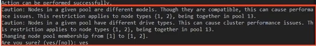
When an F210 is added to the F200 node pool, OneFS will display the following WebUI warning message alerting to this ‘soft restriction’:
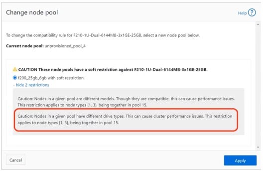
And similarly from the CLI: