Caching occurs in OneFS at multiple levels, and for a variety of types of data. For this discussion we’ll concentrate on the caching of file system structures in main memory and on SSD.
OneFS’ caching infrastructure design is based on aggregating each individual node’s cache into one cluster wide, globally accessible pool of memory. This is done by using an efficient messaging system, which allows all the nodes’ memory caches to be available to each and every node in the cluster.
For remote memory access, OneFS utilizes the Sockets Direct Protocol (SDP) over an Ethernet or Infiniband (IB) backend interconnect on the cluster. SDP provides an efficient, socket-like interface between nodes which, by using a switched star topology, ensures that remote memory addresses are only ever one hop away. While not as fast as local memory, remote memory access is still very fast due to the low latency of the backend network.
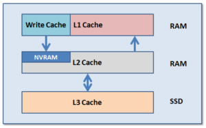
OneFS uses up to three levels of read cache, plus an NVRAM-backed write cache, or write coalescer. The first two types of read cache, level 1 (L1) and level 2 (L2), are memory (RAM) based, and analogous to the cache used in CPUs. These two cache layers are present in all Isilon storage nodes. An optional third tier of read cache, called SmartFlash, or Level 3 cache (L3), is also configurable on nodes that contain solid state drives (SSDs). L3 cache is an eviction cache that is populated by L2 cache blocks as they are aged out from memory.

The OneFS caching subsystem is coherent across the cluster. This means that if the same content exists in the private caches of multiple nodes, this cached data is consistent across all instances. For example, consider the following scenario:
- Node 2 and Node 4 each have a copy of data located at an address in shared cache.
- Node 4, in response to a write request, invalidates node 2’s copy.
- Node 4 then updates the value.
- Node 2 must re-read the data from shared cache to get the updated value.
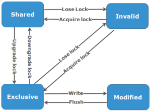
OneFS utilizes the MESI Protocol to maintain cache coherency, implementing an “invalidate-on-write” policy to ensure that all data is consistent across the entire shared cache. The various states that in-cache data can take are:
M – Modified: The data exists only in local cache, and has been changed from the value in shared cache. Modified data is referred to as ‘dirty’.
E – Exclusive: The data exists only in local cache, but matches what is in shared cache. This data referred to as ‘clean’.
S – Shared: The data in local cache may also be in other local caches in the cluster.
I – Invalid: A lock (exclusive or shared) has been lost on the data.

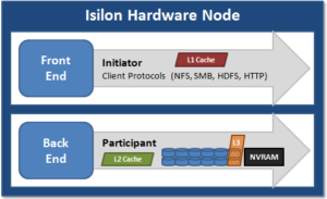
L1 cache, or front-end cache, is memory that is nearest to the protocol layers (e.g. NFS, SMB, etc) used by clients, or initiators, connected to that node. The main task of L1 is to prefetch data from remote nodes. Data is pre-fetched per file, and this is optimized in order to reduce the latency associated with the nodes’ IB back-end network. Since the IB interconnect latency is relatively small, the size of L1 cache, and the typical amount of data stored per request, is less than L2 cache.
L1 is also known as remote cache because it contains data retrieved from other nodes in the cluster. It is coherent across the cluster, but is used only by the node on which it resides, and is not accessible by other nodes. Data in L1 cache on storage nodes is aggressively discarded after it is used. L1 cache uses file-based addressing, in which data is accessed via an offset into a file object. The L1 cache refers to memory on the same node as the initiator. It is only accessible to the local node, and typically the cache is not the primary copy of the data. This is analogous to the L1 cache on a CPU core, which may be invalidated as other cores write to main memory. L1 cache coherency is managed via a MESI-like protocol using distributed locks, as described above.

L2, or back-end cache, refers to local memory on the node on which a particular block of data is stored. L2 reduces the latency of a read operation by not requiring a seek directly from the disk drives. As such, the amount of data prefetched into L2 cache for use by remote nodes is much greater than that in L1 cache.
L2 is also known as local cache because it contains data retrieved from disk drives located on that node and then made available for requests from remote nodes. Data in L2 cache is evicted according to a Least Recently Used (LRU) algorithm. Data in L2 cache is addressed by the local node using an offset into a disk drive which is local to that node. Since the node knows where the data requested by the remote nodes is located on disk, this is a very fast way of retrieving data destined for remote nodes. A remote node accesses L2 cache by doing a lookup of the block address for a particular file object. As described above, there is no MESI invalidation necessary here and the cache is updated automatically during writes and kept coherent by the transaction system and NVRAM.
L3 cache is a subsystem which caches evicted L2 blocks on a node. Unlike L1 and L2, not all nodes or clusters have an L3 cache, since it requires solid state drives (SSDs) to be present and exclusively reserved and configured for caching use. L3 serves as a large, cost-effective way of extending a node’s read cache from gigabytes to terabytes. This allows clients to retain a larger working set of data in cache, before being forced to retrieve data from higher latency spinning disk. The L3 cache is populated with “interesting” L2 blocks dropped from memory by L2’s least recently used cache eviction algorithm. Unlike RAM based caches, since L3 is based on persistent flash storage, once the cache is populated, or warmed, it’s highly durable and persists across node reboots, etc. L3 uses a custom log-based filesystem with an index of cached blocks. The SSDs provide very good random read access characteristics, such that a hit in L3 cache is not that much slower than a hit in L2.
To utilize multiple SSDs for cache effectively and automatically, L3 uses a consistent hashing approach to associate an L2 block address with one L3 SSD. In the event of an L3 drive failure, a portion of the cache will obviously disappear, but the remaining cache entries on other drives will still be valid. Before a new L3 drive may be added to the hash, some cache entries must be invalidated.
OneFS also uses a dedicated inode cache in which recently requested inodes are kept. The inode cache frequently has a large impact on performance, because clients often cache data, and many network I/O activities are primarily requests for file attributes and metadata, which can be quickly returned from the cached inode.
OneFS provides tools to accurately assess the performance of the various levels of cache at a point in time. These cache statistics can be viewed from the OneFS CLI using the isi_cache_stats command. Statistics for L1, L2 and L3 cache are displayed for both data and metadata. For example:
# isi_cache_stats
Totals

l1_data: a 224G 100% r 226G 100% p 318M 77%, l1_encoded: a 0.0B 0% r 0.0B 0% p 0.0B 0%, l1_meta: r 4.5T 99% p 152K 48%,

l2_data: r 1.2G 95% p 115M 79%, l2_meta: r 27G 72% p 28M 3%,

l3_data: r 0.0B 0% p 0.0B 0%, l3_meta: r 8G 99% p 0.0B 0%
For more detailed and formatted output, a verbose option of the command is available using the ‘isi_cache_stats -v’ option.
It’s worth noting that for L3 cache, the prefetch statistics will always read zero, since it’s a pure eviction cache and does not utilize data or metadata prefetch.
Due to balanced data distribution, automatic rebalancing, and distributed processing, OneFS is able to leverage additional CPUs, network ports, and memory as the system grows. This also allows the caching subsystem (and, by virtue, throughput and IOPS) to scale linearly with the cluster size.