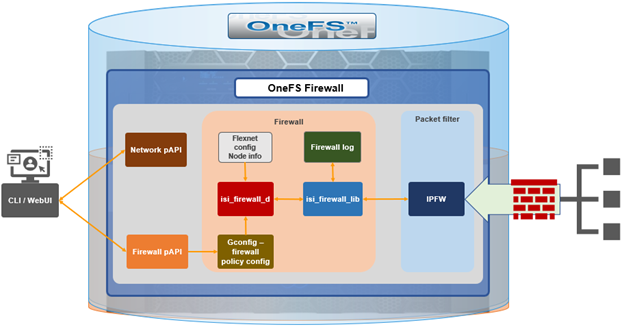
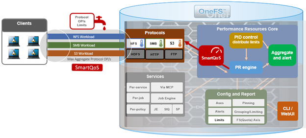
The new firewall in OneFS 9.5 enhances the security of the cluster and helps prevent unauthorized access to the storage system. When enabled, the default firewall configuration allows remote systems access to a specific set of default services for data, management, and inter-cluster interfaces (network pools).
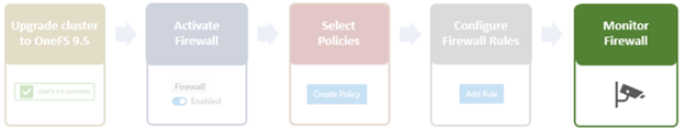
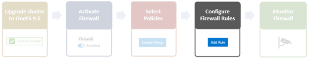
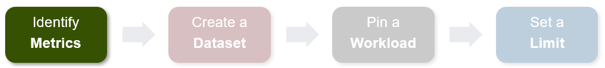
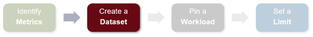
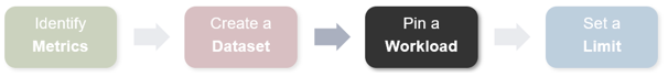
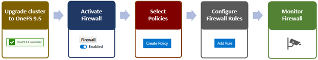
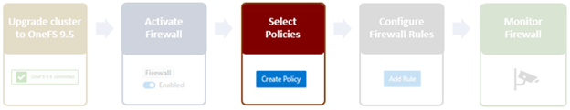
The basic OneFS firewall provisioning process is as follows:
Note that role-based access control (RBAC) explicitly limits who has access to manage the OneFS firewall. In addition to the ubiquitous ‘root’, the cluster’s built-in SystemAdmin role has write privileges to configure and administer the firewall.
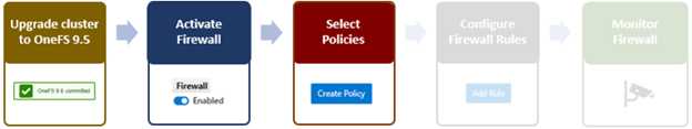
- Upgrade to OneFS 9.5
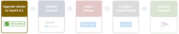
First, the cluster must be running OneFS 9.5 in order to provision the firewall.
If upgrading from an earlier release, the OneFS 9.5 upgrade must be committed before enabling the firewall.
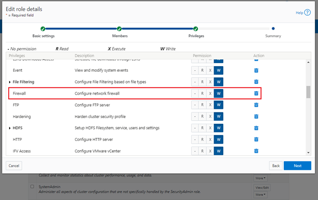
Also, be aware that configuration and management of the firewall in OneFS 9.5 requires the new ISI_PRIV_FIREWALL administration privilege. This can be granted to a role with either read-only or read-write privileges.
# isi auth privilege | grep -i firewall

ISI_PRIV_FIREWALL                   Configure network firewall
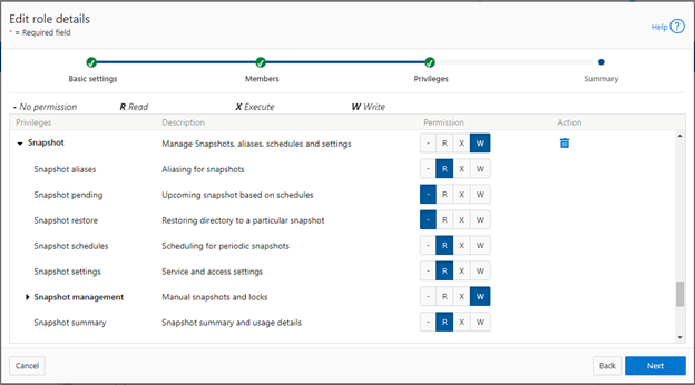
This privilege can be granted to a role with either read-only or read-write permissions. By default, the built-in ‘SystemAdmin’ roles is granted write privileges to administer the firewall:
# isi auth roles view SystemAdmin | grep -A2 -i firewall

             ID: ISI_PRIV_FIREWALL

     Permission: w
Additionally, the built-in ‘AuditAdmin’ role has read permission to view the firewall configuration and logs, etc:
# isi auth roles view AuditAdmin | grep -A2 -i firewall

             ID: ISI_PRIV_FIREWALL

     Permission: r
Ensure that the user account which will be used to enable and configure the OneFS firewall belongs to a role with the ‘ISI_PRIV_FIREWALL’ write privilege.
- Activate Firewall
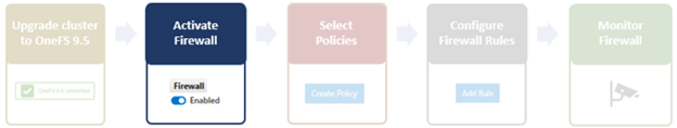
As mentioned previously, the OneFS firewall can be either ‘enabled’ or ‘disabled’, with the latter as the default state. The following CLI syntax will display the firewall’s global status – in this case ‘disabled’ (the default):
# isi network firewall settings view

Enabled: False
Firewall activation can be easily performed from the CLI as follows:
# isi network firewall settings modify --enabled true

# isi network firewall settings view

Enabled: True
Or from the WebUI under Cluster management > Firewall Configuration > Settings:
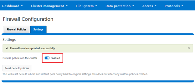
Note that the firewall is automatically enabled when STIG Hardening applied to a cluster.
- Pick policies
A cluster’s existing firewall policies can be easily viewed from the CLI with the following command:
# isi network firewall policies list

ID        Pools                    Subnets                   Rules
-----------------------------------------------------------------------------
fw_test1  groupnet0.subnet0.pool0  groupnet0.subnet1         test_rule1
-----------------------------------------------------------------------------
Total: 1
Or from the WebUI under Cluster management > Firewall Configuration > Firewall Policies:
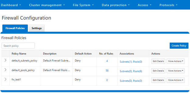
The OneFS firewall offers four main strategies when it comes to selecting a firewall policy. These include:
- Retaining the default policy
- Reconfiguring the default policy
- Cloning the default policy and reconfiguring
- Creating a custom firewall policy
We’ll consider each of these strategies in order:
a. Retaining the default policy
In many cases, the default OneFS firewall policy value will provide acceptable protection for a security conscious organization. In these instances, once the OneFS firewall has been enabled on a cluster, no further configuration is required, and the cluster administrators can move on to the management and monitoring phase.
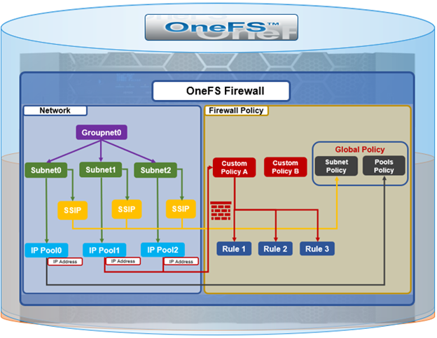
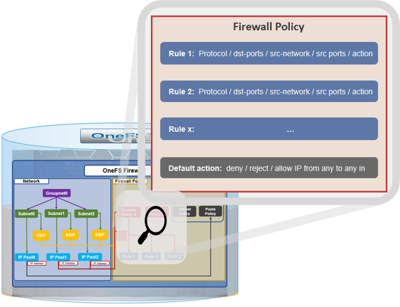
The firewall policy for all front-end cluster interfaces (network pool) is ‘default’. While the default policy can be modified, be aware that this default policy is global. As such, any change against it will impact all network pools using this default policy.
The following table describes the default firewall policies that are assigned to each interface:
| Policy |
Description |
| Default pools policy |
Contains rules for the inbound default ports for TCP and UDP services in OneFS. |
| Default subnets policy |
Contains rules for:
· DNS port 53
· Rule for ICMP
· Rule for ICMP6 |
These can be viewed from the CLI as follows:
# isi network firewall policies view default_pools_policy
ID: default_pools_policy
Name: default_pools_policy
Description: Default Firewall Pools Policy
Default Action: deny
Max Rules: 100
Pools: groupnet0.subnet0.pool0, groupnet0.subnet0.testpool1, groupnet0.subnet0.testpool2, groupnet0.subnet0.testpool3, groupnet0.subnet0.testpool4, groupnet0.subnet0.poolcava
Subnets: -
Rules: rule_ldap_tcp, rule_ldap_udp, rule_reserved_for_hw_tcp, rule_reserved_for_hw_udp, rule_isi_SyncIQ, rule_catalog_search_req, rule_lwswift, rule_session_transfer, rule_s3, rule_nfs_tcp, rule_nfs_udp, rule_smb, rule_hdfs_datanode, rule_nfsrdma_tcp, rule_nfsrdma_udp, rule_ftp_data, rule_ftps_data, rule_ftp, rule_ssh, rule_smtp, rule_http, rule_kerberos_tcp, rule_kerberos_udp, rule_rpcbind_tcp, rule_rpcbind_udp, rule_ntp, rule_dcerpc_tcp, rule_dcerpc_udp, rule_netbios_ns, rule_netbios_dgm, rule_netbios_ssn, rule_snmp, rule_snmptrap, rule_mountd_tcp, rule_mountd_udp, rule_statd_tcp, rule_statd_udp, rule_lockd_tcp, rule_lockd_udp, rule_nfsrquotad_tcp, rule_nfsrquotad_udp, rule_nfsmgmtd_tcp, rule_nfsmgmtd_udp, rule_https, rule_ldaps, rule_ftps, rule_hdfs_namenode, rule_isi_webui, rule_webhdfs, rule_ambari_handshake, rule_ambari_heartbeat, rule_isi_esrs_d, rule_ndmp, rule_isi_ph_rpcd, rule_cee, rule_icmp, rule_icmp6, rule_isi_dm_d
# isi network firewall policies view default_subnets_policy
ID: default_subnets_policy
Name: default_subnets_policy
Description: Default Firewall Subnets Policy
Default Action: deny
Max Rules: 100
Pools: -
Subnets: groupnet0.subnet0
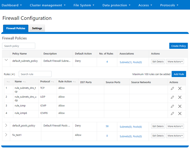
Rules: rule_subnets_dns_tcp, rule_subnets_dns_udp, rule_icmp, rule_icmp6
Or from the WebUI under Cluster Management > Firewall Configuration > Firewall Policies:
b. Reconfiguring the default policy
Depending on an organization’s threat levels or security mandates, there may be a need to restrict access to certain additional IP addresses and/or management service protocols.
If the default policy is deemed insufficient, reconfiguring the default firewall policy can be a good option if only a small number of rule changes are required. The specifics of creating, modifying, and deleting individual firewall rules is covered later in this article (step 3 below).
Note that if new rule changes behave unexpectedly, or configurating the firewall generally goes awry, OneFS does provide a ‘get out of jail free’ card. In a pinch, the global firewall policy can be quickly and easily restored to its default values. This can be achieved with the following CLI syntax:
# isi network firewall reset-global-policy

This command will reset the global firewall policies to the original system defaults. Are you sure you want to continue? (yes/[no]):
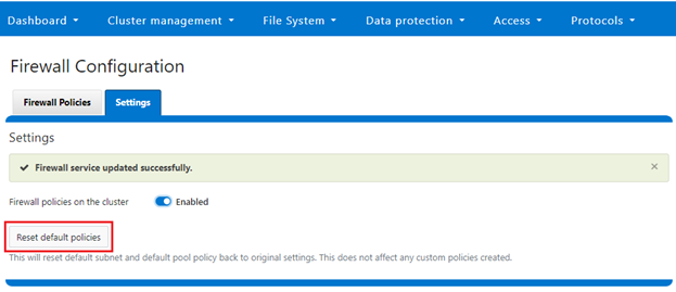
Alternatively, the default policy can also be easily reverted from the WebUI too, by clicking the ‘Reset default policies’ button:
c. Cloning the default policy and reconfiguring
Another option is cloning, which can be useful when batch modification or a large number of changes to the current policy are required. By cloning the default firewall policy, an exact copy of the existing policy and its rules is generated, but with a new policy name. For example:
# isi network firewall policies clone default_pools_policy clone_default_pools_policy

# isi network firewall policies list | grep -i clone

clone_default_pools_policy -
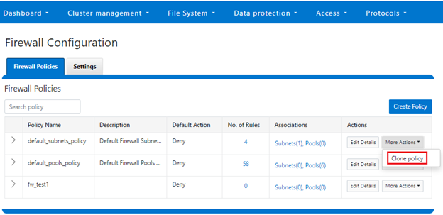
Cloning can also be initiated from the WebUI under Firewall Configuration > Firewall Policies > More Actions > Clone Policy:
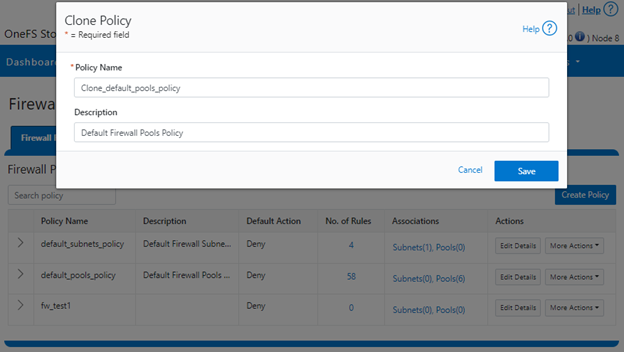
Enter the desired name of the clone in the ‘Policy Name’ field in the pop-up window and click ‘Save’:
Once cloned, the policy can then be easily reconfigured to suit. For example, to modify the policy ‘fw_test1’ and change its default-action from deny-all to allow-all:
# isi network firewall policies modify fw_test1 --default--action allow-all
When modifying a firewall policy, the ‘–live’ option CLI option can be used to force it take effect immediately. Note that the ‘—live’ option is only valid when issuing a command to modify or delete an active custom policy and to modify default policy. Such changes will take effect immediately on all network subnets and pools associated with this policy. Using the live option on an inactive policy will be rejected, and an error message returned.
Options for creating or modifying a firewall policy include:
| Option |
Description |
| –default-action |
Automatically add one rule to ‘deny all’ or ‘allow all’ to the bottom of the rule set for this created policy (Index = 100). |
| —max-rule-num |
By default, each policy when created could have maximum 100 rules (include one default rule), so user could config maximum 99 rules. User could expand the maximum rule number to a specified value. Currently this value is limited to 200 (and user could config maximum 199 rules). |
| –add-subnets |
Specify the network subnet(s) to add to policy, separated by a comma. |
| –remove-subnets |
Specify the networks subnets to remove from policy and fall back to global policy. |
| –add-pools |
Specify the network pool(s) to add to policy, separated by a comma. |
| –remove-pools |
Specify the networks pools to remove from policy and fall back to global policy. |
When modifying firewall policies, OneFS prints the following warning to verify the changes and help avoid the risk of a self-induced denial-of-service:
# isi network firewall policies modify --pools groupnet0.subnet0.pool0 fw_test1
Changing the Firewall Policy associated with a subnet or pool may change the networks and/or services allowed to connect to OneFS. Please confirm you have selected the correct Firewall Policy and Subnets/Pools. Are you sure you want to continue? (yes/[no]): yes
Once again, having the following CLI command handy, plus console access to the cluster is always a prudent move:
# isi network firewall reset-global-policy
So adding network pools or subnets to a firewall policy will cause the previous policy to be removed from them. Similarly, adding network pools or subnets to the global default policy will revert any custom policy configuration they might have. For example, to apply the firewall policy fw_test1 to IP Pool groupnet0.subnet0.pool0 and groupnet0.subnet0.pool1:
# isi network pools view groupnet0.subnet0.pool0 | grep -i firewall

      Firewall Policy: default_pools_policy

# isi network firewall policies modify fw_test1 --add-pools groupnet0.subnet0.pool0, groupnet0.subnet0.pool1

# isi network pools view groupnet0.subnet0.pool0 | grep -i firewall

      Firewall Policy: fw_test1
Or to apply the firewall policy fw_test1 to IP Pool groupnet0.subnet0.pool0 and groupnet0.subnet0:
# isi network firewall policies modify fw_test1 --apply-subnet groupnet0.subnet0.pool0, groupnet0.subnet0

# isi network pools view groupnet0.subnet0.pool0 | grep -i firewall

 Firewall Policy: fw_test1

# isi network subnets view groupnet0.subnet0 | grep -i firewall

 Firewall Policy: fw_test1
To reapply global policy at any time, either add the pools to the default policy:
# isi network firewall policies modify default_pools_policy --add-pools groupnet0.subnet0.pool0, groupnet0.subnet0.pool1

# isi network pools view groupnet0.subnet0.pool0 | grep -i firewall

 Firewall Policy: default_subnets_policy

# isi network subnets view groupnet0.subnet1 | grep -i firewall

 Firewall Policy: default_subnets_policy
Or remove the pool from the custom policy:
# isi network firewall policies modify fw_test1 --remove-pools groupnet0.subnet0.pool0 groupnet0.subnet0.pool1
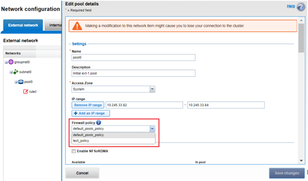
Firewall policies can also be managed on the desired network pool in the OneFS WebUI by navigating to Cluster configuration > Network configuration > External network > Edit pool details. For example:
Be aware that cloning is also not limited to the default policy, as clones can be made of any custom policies too. For example:
# isi network firewall policies clone clone_default_pools_policy fw_test1
d. Creating a custom firewall policy
Alternatively, a custom firewall policy can also be created from scratch. This can be accomplished from the CLI using the following syntax, in this case to create a firewall policy named ‘fw_test1’:
# isi network firewall policies create fw_test1 --default-action deny

# isi network firewall policies view fw_test1

            ID: fw_test1

          Name: fw_test1

   Description:

Default Action: deny

     Max Rules: 100

         Pools: -

       Subnets: -

         Rules: -
Note that if a ‘default-action’ is not specified in the CLI command syntax, it will automatically default to deny.
Firewall policies can also be configured via the OneFS WebUI by navigating to Cluster management > Firewall Configuration > Firewall Policies > Create Policy:
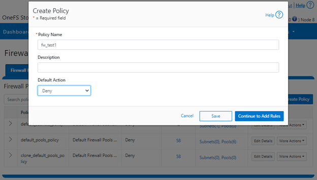
However, in contrast to the CLI, if a ‘default-action’ is not specified when creating a policy in the WebUI, it will automatically default to ‘Allow’ instead, since the drop-down list works alphabetically.
If and when a firewall policy is no longer required, it can be swiftly and easily removed. For example, the following CLI syntax will delete the firewall policy ‘fw_test1’, clearing out any rules within this policy container:
# isi network firewall policies delete fw_test1

Are you sure you want to delete firewall policy fw_test1? (yes/[no]): yes
Note that the default global policies cannot be deleted.
# isi network firewall policies delete default_subnets_policy

Are you sure you want to delete firewall policy default_subnets_policy? (yes/[no]): yes

Firewall policy: Cannot delete default policy default_subnets_policy.
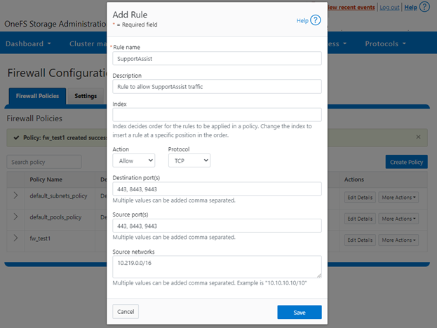
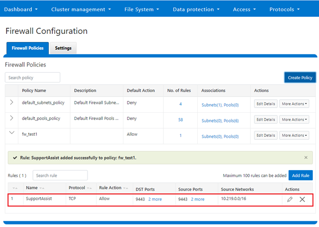
- Configuring Firewall Rules

In the next article in this series, we’ll turn our attention to configuring the OneFS firewall rule(s) (step 4).