In this article, we turn our attention to some of the environmental and logistical aspects of cluster design, installation and management.
In addition to available rack space and physical proximity of nodes, provision needs to be made for adequate power and cooling as the cluster expands. New generations of drives and nodes typically deliver increased storage density, which often magnifies the power draw and cooling requirements per rack unit.
The recommendation is for a large cluster’s power supply to be fully redundant and backed up with a battery UPS and/or power generator. In the worst instance, if a cluster does loose power, the nodes are protected internally by filesystem journals which preserve any in-flight uncommitted writes. However, the time to restore power and bring up a large cluster from an unclean shutdown can be considerable.
Like most data center equipment, the cooling fans in PowerScale nodes and switches pull air from the front to back of the chassis. To complement this, data centers often employ a hot isle/cold isle rack configuration, where cool, low humidity air is supplied in the aisle at the front of each rack or cabinet either at the floor or ceiling level, and warm exhaust air is returned at ceiling level in the aisle to the rear of each rack.
Given the significant power draw, heat density, and weight of cluster hardware, some datacenters are limited in the number of nodes each rack can support. For partially filled racks, the use of blank panels to cover the front and rear of any unfilled rack units can help to efficiently direct airflow through the equipment.
The table below shows the various front and back-end network speeds and connector form factors across the PowerScale storage node portfolio.
| Speed (Gb/s) | Form Factor | Front-end/
Back-end |
Supported Nodes |
| 100/40 | QSFP28 | Back-end | F900, F600, H700, H7000, A300, A3000, P100, B100 |
| 40
QDR |
QSFP+ | Back-end | F800, F810, H600, H5600, H500, H400, A200, A2000 |
| 25/10 | SFP28 | Back-end | F900, F600, F200, H700, H7000, A300, A3000, P100, B100 |
| 10
QDR |
QSFP+ | Back-end | H400, A200, A2000 |
| 100/40 | QSFP28 | Front-end | F900, F600, H700, H7000, A300, A3000, P100, B100 |
| 40
QDR |
QSFP+ | Front-end | F800, F810, H600, H5600, H500, H400, A200, A2000 |
| 25/10 | SFP28 | Front-end | F900, F600, F200, H700, H7000, A300, A3000, P100, B100 |
| 25/10 | SFP+ | Front-end | F800, F810, H600, H5600, H500, H400, A200, A2000 |
| 10
QDR |
SFP+ | Front-end | F800, F810, H600, H5600, H500, H400, A200, A2000 |
With large clusters, especially when the nodes may not be racked in a contiguous manner, having all the nodes and switches connected to serial console concentrators and remote power controllers is highly advised. However, to perform any physical administration or break/fix activity on nodes you must know where the equipment is located and have administrative resources available to access and service all locations.
As such, the following best practices are recommended:
- Develop and update thorough physical architectural documentation.
- Implement an intuitive cable coloring standard.
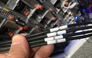
- Be fastidious and consistent about cable labeling.
- Use the appropriate length of cable for the run and create a neat 12” loop of any excess cable, secured with Velcro.
- Observe appropriate cable bend ratios, particularly with fiber cables.
- Dress cables and maintain a disciplined cable management ethos.
- Keep a detailed cluster hardware maintenance log.
- Where appropriate, maintain a ‘mailbox’ space for cable management.
Disciplined cable management and labeling for ease of identification is particularly important in larger PowerScale clusters, where density of cabling is high. Each chassis can require up to twenty eight cables, as shown in the table below:
| Cabling Component | Medium | Cable Quantity per Chassis
|
| Back end network | Ethernet or Infiniband | 8 |
| Front end network | Ethernet | 8 |
| Management Interface | 1Gb Ethernet | 4 |
| Serial Console | DB9 RS 232 | 4 |
| Power cord | 110V or 220V AC power | 4 |
| Total | 28 |
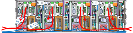
The recommendation for cabling a PowerScale chassis is as follows:
- Split cabling in the middle of the chassis, between nodes 2 and 3.
- Route Ethernet and Infiniband cables towards lower side of the chassis.
- Connect power cords for nodes 1 and 3 to PDU A and power cords for nodes 2 and 4 to PDU B.
- Bundle network cables with the AC power cords for ease of management.
- Leave enough cable slack for servicing each individual node’s FRUs.
Similarly, the stand-alone F-series all flash nodes, in particular the 1RU F600 and F200 nodes, also have a similar density of cabling per rack unit:
| Cabling Component | Medium | Cable Quantity per F-series node
|
| Back end network | 10 or 40 Gb Ethernet or QDR Infiniband | 2 |
| Front end network | 10 or 40Gb Ethernet | 2 |
| Management Interface | 1Gb Ethernet | 1 |
| Serial Console | DB9 RS 232 | 1 |
| Power cord | 110V or 220V AC power | 2 |
| Total | 8 |
Consistent and meticulous cable labeling and management is particularly important in large clusters. PowerScale chassis that employ both front and back end Ethernet networks can include up to twenty Ethernet connections per 4RU chassis.
In each node’s compute module, there are two PCI slots for the Ethernet cards (NICs). Viewed from the rear of the chassis, in each node the right hand slot (HBA Slot 0) houses the NIC for the front end network, and the left hand slot (HBA Slot 1) the NIC for the front end network. In addition to this, there is a separate built-in 1Gb Ethernet port on each node for cluster management traffic.
While there is no requirement that node 1 aligns with port 1 on each of the backend switches, it can certainly make cluster and switch management and troubleshooting considerably simpler. Even if exact port alignment is not possible, with large clusters, ensure that the cables are clearly labeled and connected to similar port regions on the backend switches.
PowerScale nodes and the drives they contain have identifying LED lights to indicate when a component has failed and to allow proactive identification of resources. The ‘isi led’ CLI command can be used to proactive illuminate specific node and drive indicator lights to aid in identification.
Drive repair times depend on a variety of factors:
- OneFS release (determines Job Engine version and how efficiently it operates)
- System hardware (determines drive types, amount of CPU and RAM, etc)
- Filesystem: Amount of data, data composition (lots of small vs large files), protection, tunables, etc.
- Load on the cluster during the drive failure
A useful method to estimate future FlexProtect runtime is to use old repair runtimes as a guide, if available.
The drives in the PowerScale chassis-based platforms have a bay-grid nomenclature, where A-E indicates each of the sleds and 0-6 would point to the drive position in the sled. The drive closest to the front is 0, whereas the drive closest to the back is 2/3/5, depending on the drive sled type.
When it comes to updating and refreshing hardware in a large cluster, swapping nodes can be a lengthy process of somewhat unpredictable duration. Data has to be evacuated from each old node during the Smartfail process prior to its removal, and restriped and balanced across the new hardware’s drives. During this time there will also be potentially impactful group changes as new nodes are added and the old ones removed.
However, if replacing an entire node-pool as part of a tech refresh, a SmartPools filepool policy can be crafted to migrate the data to another nodepool across the back-end network. When complete, the nodes can then be Smartfailed out, which should progress swiftly since they are now empty.
If multiple nodes are Smartfailed simultaneously, at the final stage of the process the node remove is serialized with around 60 seconds pause between each. The Smartfail job places the selected nodes in read-only mode while it copies the protection stripes to the cluster’s free space. Using SmartPools to evacuate data from a node or set of nodes in preparation to remove them is generally a good idea, and is usually a relatively fast process.