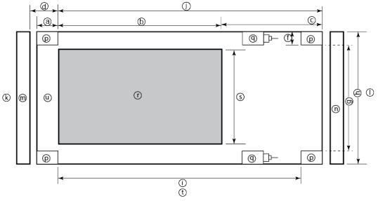
When it comes to physically installing PowerScale nodes, most utilize a 35 inch depth chassis and will fit in a standard depth data center cabinet. Nodes can be secured to standard storage racks with their sliding rail kits, included in all node packaging and compatible with racks using either 3/8 inch square holes, 9/32 inch round holes, or 10-32 / 12-24 / M5X.8 / M6X1 pre-threaded holes. These supplied rail kit mounting brackets are adjustable in length from 24 inches to 36 inches to accommodate different rack depths. When selecting an enclosure for PowerScale nodes, ensure that the rack supports the minimum and maximum rail kit sizes.
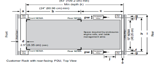
| Rack Component | Description |
| a | Distance between front surface of the rack and the front NEMA rail |
| b | Distance between NEMA rails, minimum=24in (609.6mm), max=34in (863.6mm) |
| c | Distance between the rear of the chassis to the rear of the rack, min=2.3in (58.42mm) |
| d | Distance between inner front of the front door and the NEMA rail, min=2.5in (63.5mm) |
| e | Distance between the inside of the rear post and the rear vertical edge of the chassis and rails, min=2.5in (63.5mm) |
| f | Width of the rear rack post |
| g | 19in (486.2mm)+(2e), min=24in (609.6mm) |
| h | 19in (486.2mm) NEMA+(2e)+(2f)
Note: Width of the PDU+0.5in (13mm) <=e +f If j=i+c+PDU depth+3in (76.2mm), then h=min 23.6in (600mm) Assuming the PDU is mounted beyond i+c. |
| i | Chassis depth: Normal chassis=35.80in (909mm) : Deep chassis=40.40in (1026mm)
Switch depth (measured from the front NEMA rail): Note: The inner rail is fixed at 36.25in (921mm) Allow up to 6in (155mm) for cable bend radius when routing up to 32 cables to one side of the rack. Select the greater of the installed equipment. |
| j | Minimum rack depth=i+c |
| k | Front |
| l | Rear |
| m | Front door |
| n | Rear door |
| p | Rack post |
| q | PDU |
| r | NEMA |
| s | NEMA 19 inch |
| t | Rack top view |
| u | Distance from front NEMA to chassis face:
Dell PowerScale deep and normal chassis = 0in |
However, the high capacity models such as the F800/810, H7000, H5600, A3000 and A2000 have 40 inch depth chassis and require extended depth cabinets such as the APC 3350 or Dell Titan-HD rack.
Additional room must be provided for opening the FRU service trays at the rear of the nodes and, in the chassis-based 4RU platforms, the disk sleds at the front of the chassis. With the exception of the 2RU F900, the stand-alone PowerScale all-flash nodes are 1RU in height (including the 1RU diskless P100 accelerator and B100 backup accelerator nodes).
Power-wise, each cabinet typically requires between two and six independent single or three-phase power sources. To determine the specific requirements, use the published technical specifications and device rating labels for the devices to calculate the total current draw for each rack.
| Specification | North American 3 wire connection (2 L and 1 G) | International 3 wire connection (1 L, 1 N, and 1 G) |
| Input nominal voltage | 200–240 V ac +/- 10% L – L nom | 220–240 V ac +/- 10% L – L nom |
| Frequency | 50–60 Hz | 50–60 Hz |
| Circuit breakers | 30 A | 32 A |
| Power zones | Two | Two |
| Power requirements at site (minimum to maximum) | Single-phase: six 30A drops, two per zone
Three-phase Delta: two 50A drops, one per zone Three-phase Wye: two 32A drops, one per zone |
Single-phase: six 30A drops, two per zone
Three-phase Delta: two 50A drops, one per zone Three-phase Wye: two 32A drops, one per zone |
Additionally, the recommended environmental conditions to support optimal PowerScale cluster operation are as follows:
| Attribute | Details |
| Temperature | Operate at >=90 percent of the time between 10 degrees celsiuses to 35 degrees celsius degrees celsius, and <=10 percent of the time between 5 degrees celsiuses to 40 degrees celsiuses. |
| Humidity | 40 to 55 percent relative humidity |
| Weight | A fully configured cabinet must sit on at least two floor tiles, and can weigh approximately 1588 kilograms (3500 pounds). |
| Altitude | 0 meters to 2439 meters (0 to 8,000 ft) above sea level operating altitude. |
Weight is a critical factor to keep in mind, particularly with the chassis-based nodes. Individual 4RU chassis can weigh up to around 300lbs each, and the maximum floor tile capacity for each individual cabinet or rack must be kept in mind. For the deep node styles (H7000, H5600, A3000 and A2000), the considerable node weight may prevent racks from being fully populated with PowerScale equipment. If the cluster uses a variety of node types, installing the larger, heavier nodes at the bottom of each rack and the lighter chassis at the top can help distribute weight evenly across the cluster racks’ floor tiles.
Note that there are no lift handles on the PowerScale 4RU chassis. However, the drive sleds can be removed to provide handling points if no lift is available. With all the drive sleds removed, but leaving the rear compute modules inserted, the chassis weight drops to a more manageable 115lbs or so. It is strongly recommended to use a lift for installation of 4RU chassis.
Cluster backend switches ship with the appropriate rails (or tray) for proper installation of the switch in the rack. These rail kits are adjustable to fit NEMA front rail to rear rail spacing ranging from 22 in to 34 in.
Note that some manufacturers Ethernet switch rails are designed to overhang the rear NEMA rails, helping to align the switch with the PowerScale chassis at the rear of the rack. These require a minimum clearance of 36 in from the front NEMA rail to the rear of the rack, in order to ensure that the rack door can be closed.
Consider the following large cluster topology, for example:
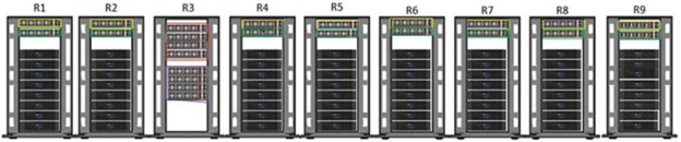
This contiguous rack architecture is designed to scale up to the current maximum PowerScale cluster size of 252 nodes, in 63 4RU chassis, across nine racks as the environment grows – while still keeping cable management relatively simple. Note that this configuration assumes 1RU per node. If using F900 nodes, which are 2RU in size, additional rack capacity should be budgeted for.
Successful large cluster infrastructures depend heavily on the proficiency of the installer and their optimizations for maintenance and future expansion. Some good data center design practices include:
- Pre-allocating and reserving adjacent racks in the same isle to fully accommodate the anticipated future cluster expansion
- Reserving an empty ‘mailbox’ slot in the top half of each rack for any pass-through cable management needs.
- Dedicating one of the racks in the group for the back-end and front-end distribution/spine switches – in this case rack R3.
For Hadoop workloads, PowerScale clusters are compatible with the rack awareness feature of HDFS to provide balancing in the placement of data. Rack locality keeps the data flow internal to the rack.
Excess cabling can be neatly stored in 12” service coils on a cable tray above the rack, if available, or at the side of the rack as illustrated below.
The use of intelligent power distribution units (PDUs) within each rack can facilitate the remote power cycling of nodes, if desired.
For deep nodes such as the H7000 and A3000 hardware, where chassis depth can be a limiting factor, horizontally mounted PDUs within the rack can be used in place of vertical PDUs, if necessary. If front-mounted, partial depth Ethernet switches are deployed, horizontal PDUs can be installed in the rear of the rack directly behind the switches to maximize available rack capacity.
With copper cables (SFP+, QSFP, CX4, etc) the maximum cable length is typically limited to 10 meters or less. After factoring in for dressing the cables to maintain some level of organization and proximity within the racks and cable trays, all the racks with PowerScale nodes need to be in close physical proximity to each other –either in the same rack row or close by in an adjacent row – or adopt a leaf-spine topology, with leaf switches in each rack.
If greater physical distance between nodes is required, support for multimode fiber (QSFP+, MPO, LC, etc) extends the cable length limitation to 150 meters. This allows nodes to be housed on separate floors or on the far side of a floor in a datacenter if necessary. While solving the floor space problem, this does have the potential to introduce new administrative and management challenges.
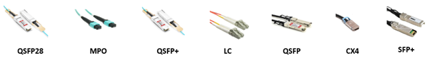
The various cable types, form factors, and supported lengths available for PowerScale nodes:
| Cable Form Factor | Medium | Speed (Gb/s) | Max Length |
| QSFP28 | Optical | 100Gb | 30M |
| MPO | Optical | 100/40Gb | 150M |
| QSFP28 | Copper | 100Gb | 5M |
| QSFP+ | Optical | 40Gb | 10M |
| LC | Optical | 25/10Gb | 150M |
| QSFP+ | Copper | 40Gb | 5M |
| SFP28 | Copper | 25Gb | 5M |
| SFP+ | Copper | 10Gb | 7M |
| CX4 | Copper | IB QDR/DDR | 10M |
The connector types for the cables above can be identified as follows:
As for the nodes themselves, the following rear views indicate the locations of the various network interfaces:
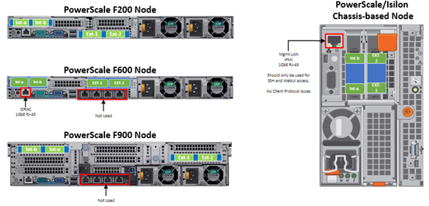
Note that Int-a and int-b indicate the primary and secondary back-end networks, whereas Ext-1 and Ext-2 are the front-end client networks interfaces.
Be aware that damage to the InfiniBand or Ethernet cables (copper or optical fibre) can negatively affect cluster performance. Never bend cables beyond the recommended bend radius, which is typically 10–12 times the diameter of the cable. For example, if a cable is 1.6 inches, round up to 2 inches and multiply by 10 for an acceptable bend radius.
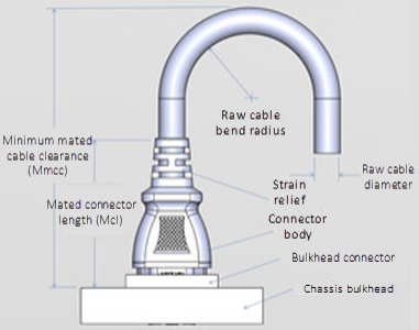
Cables differ, so follow the explicit recommendations of the cable manufacturer.
The most important design attribute for bend radius consideration is the minimum mated cable clearance (Mmcc). Mmcc is the distance from the bulkhead of the chassis through the mated connectors/strain relief including the depth of the associated 90 degree bend. Multimode fiber has many modes of light (fiber optic) traveling through the core. As each of these modes moves closer to the edge of the core, light and the signal are more likely to be reduced, especially if the cable is bent. In a traditional multimode cable, as the bend radius is decreased, the amount of light that leaks out of the core increases, and the signal decreases. Best practices for data cabling include:
- Keep cables away from sharp edges or metal corners.
- Avoid bundling network cables with power cables. If network and power cables are not bundled separately, electromagnetic interference (EMI) can affect the data stream.
- When bundling cables, do not pinch or constrict the cables.
- Avoid using zip ties to bundle cables, instead use velcro hook-and-loop ties that do not have hard edges, and can be removed without cutting. Fastening cables with velcro ties also reduces the impact of gravity on the bend radius.
Note that the effects of gravity can also decrease the bend radius and result in degradation of signal power and quality.
Cables, particularly when bundled, can also obstruct the movement of conditioned air around the cluster, and cables should be secured away from fans, etc. Flooring seals and grommets can be useful to keep conditioned air from escaping through cable holes. Also ensure that smaller Ethernet switches are drawing cool air from the front of the rack, not from inside the cabinet. This can be achieved either with switch placement or by using rack shelving.