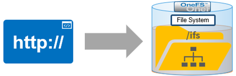
As we saw in the previous article in this series, a cluster’s files and directories can be accessed programmatically through the OneFS RESTful Access to Namespace (RAN) API, similarly to the way they’re accessed through SMB or NFS protocols – as well as controlled by filesystem permissions.
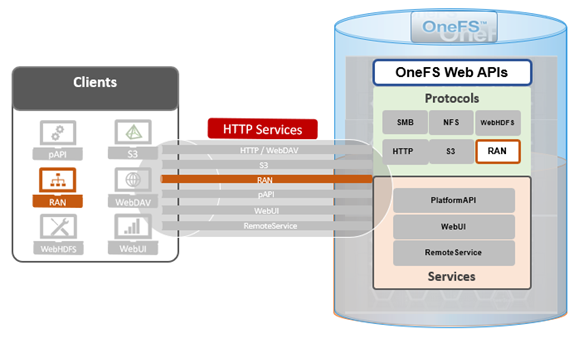
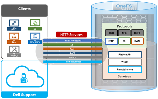
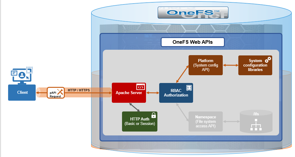
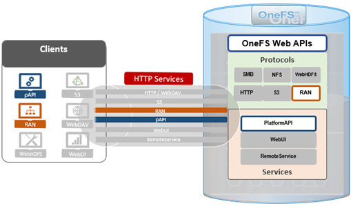
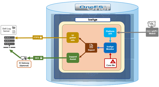
Under the hood, the general architecture and workflow of the OneFS RAN namespace API is as follows:
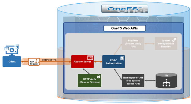
Upon receiving an HTTP request sent through the OneFS API, the cluster’s web server (Apache) verifies the username and password credentials – either through HTTP Basic Authentication for single requests or via an established session to a single node for multiple requests.
Once the user has been successfully authenticated, OneFS role-based access control (RBAC) then verifies the privileges associated with the account and, if sufficient, enables access to either the /ifs file system, or to the cluster configuration, as specified in the request URL.
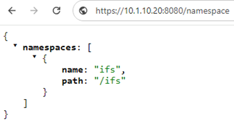
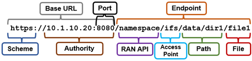
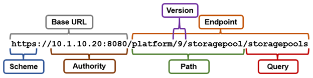
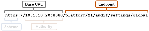
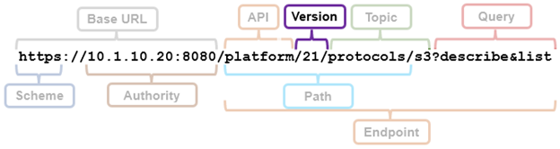
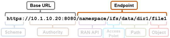
The request URL that calls the API is comprised of a base URL and end-point, with the ‘namespace’ argument denoting the RAN API. For example:
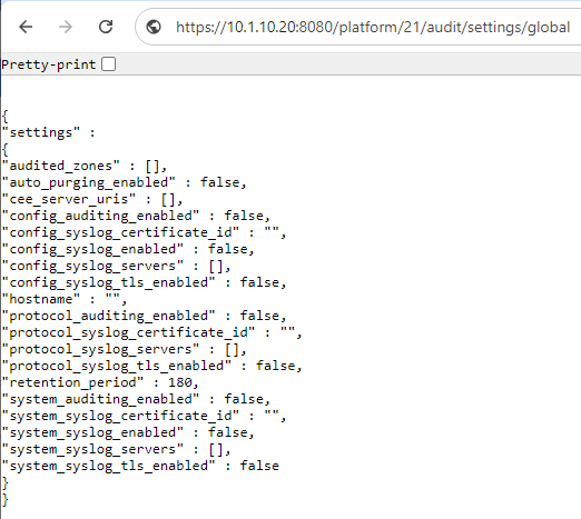
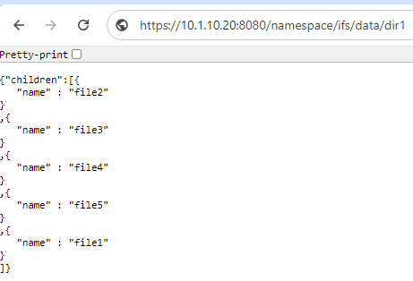
And the GET request response to a <path><object> endpoint typically yields the object’s payload. For example, the ASCII contents of the ‘file1’, in this case:
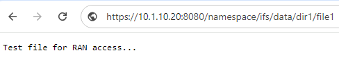
Or from the CLI with ‘curl’:
# curl -X GET https://10.1.10.20:8080/namespace/ifs/data/dir1/file2 --insecure --basic --user <user>:<passwd>

Test file for RAN access...
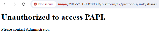
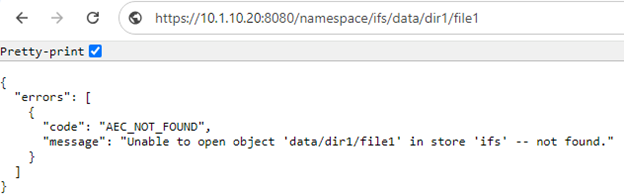
If the object is unavailable, a response similar to the following is displayed:
As we saw in the previous article in this series, RAN supports the following types of file system operations:
| Operation | Action | Description |
| Access points | CREATE, DELETE | Identify and configure access points (shares) and obtain protocol information. |
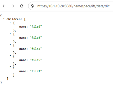
| Directory | CREATE, GET, PUT, LIST, DELETE | List directory content.; get and set directory attributes; delete directories from the file system. |
| File | CREATE, GET, PUT, LIST, DELETE | View, move, copy, and delete files from the file system. |
| Access control | GET/SET ACLs | Manage user rights; set ACL or POSIX permissions for files and directories. Set access list on access points (RAN Share Permissions). |
| Query | QUERY
|
Search system metadata or extended attributes, and tag files. |
| SmartLock | GET, SET, Commit | Allow retention dates to be set on files; commit files to a WORM state. |
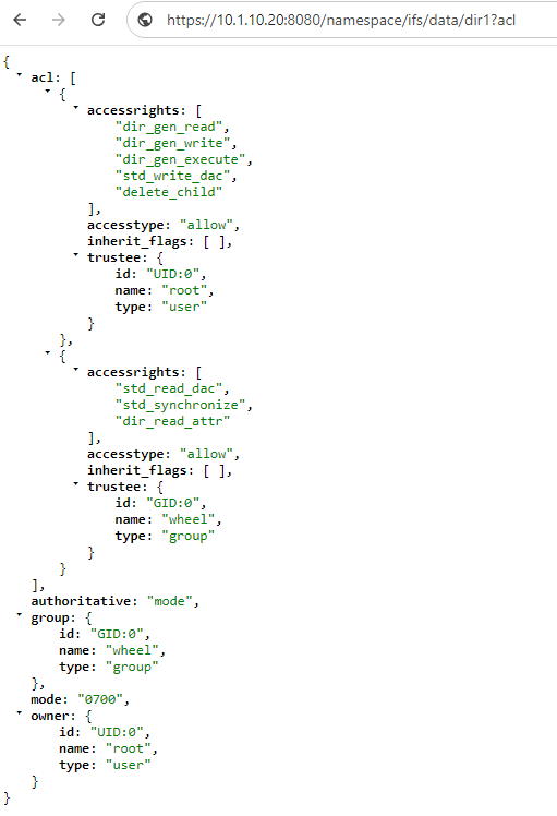
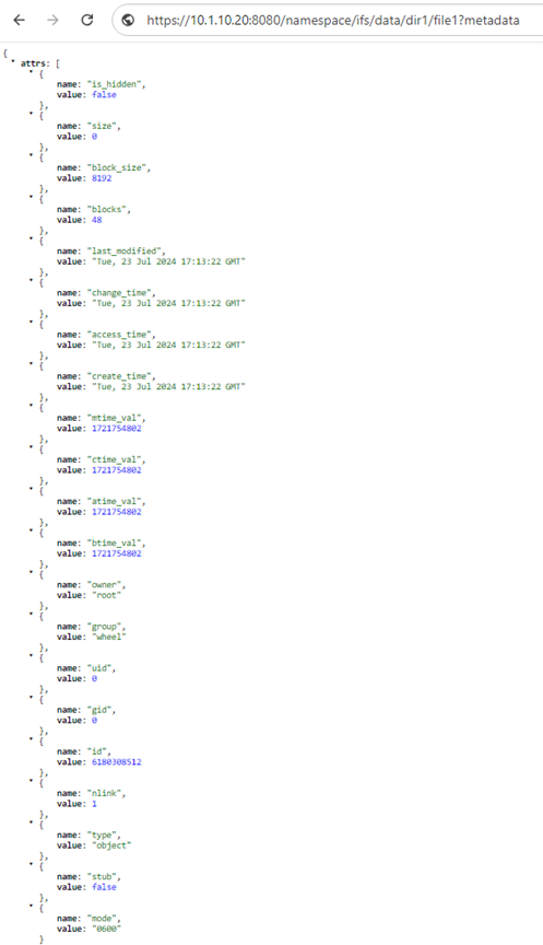
In support of these, RAN allows pre-defined keywords to be appended to the URL when sending a namespace request. These keywords must be placed first in the argument list and must not contain any value. If these keywords are placed in any other position in the argument list, the keywords are ignored. Pre-defined keywords include: ‘acl’, ‘metadata’, ‘worm’, and ‘query’.
For example:
https://<cluster_ip>:8080/namespace/ifs/data/dir1?acl
When using the ‘curl’ CLI utility, the following syntax options can be useful for crafting PUT or POST requests to RAN:
- When sending form data:
# curl -X PUT -H "Content-Type: multipart/form-data;" -F "key1=val1" "YOUR_URI"
- If sending raw data as json:
# curl -X PUT -H "Content-Type: application/json" -d '{"key1":"value"}' "YOUR_URI"
- When sending a file with a POST request:
# curl -X POST "YOUR_URI" -F 'file=@/file-path.csv'
Where:
-X – option can be used for request command,
-d – option can be used in order to put data on remote URL.
-H – header option can express the content type.
-v – Plus the verbose option, which is handy for debugging..
When sending a request to RAN, data can be accessed through customized headers, in addition to the standard HTTP headers. The common RAN HTTP request headers include:
| Name | Description | Type | Required |
| Authorization | Specifies the authentication signature. | String | Yes |
| Content-length | Specifies the length of the message body. | Integer | Conditional |
| Date | Specifies the current date according to the requestor. | HTTP-date | No. A client should only send a Date header in a request that includes an entity-body, such as in PUT and POST requests. A client without a clock must not send a Date header in a request. |
| x-isi-ifs-spec-version | Specifies the protocol specification version. The client specifies the protocol version, and the server determines if the protocol version is supported. You can test backwards compatibility with this header. | String | Conditional |
| x-isi-ifs-target-type | Specifies the resource type. For PUT operations, this value can be container or object. For GET operations, this value can be container, object, or any, or this parameter can be omitted. | String | Yes, for PUT operations.
Conditional, for GET operations. |
The following curl syntax can be used to instruct RAN to create a file, or ‘object’:
# curl -X PUT --insecure --basic --user <username>:<passwd> -H "x-isi-ifs-target-type:object" https://<cluster_ip>:8080/namespace/<path>/<file>/
For example, to create ‘testfile1’ under ‘/ifs/data’:
# ls -lsia /ifs/data/testfile1

ls: /ifs/data/testfile1: No such file or directory

# curl -X PUT --insecure --basic --user <username>:<passwd> -H "x-isi-ifs-target-type:object" https://10.1.10.20:8080/namespace/ifs/data/testfile1/

# ls -lsia /ifs/data/testfile1

6668484639 64 -rw-------     1 root  wheel  0 Aug 28 00:58 /ifs/data/testfile1
And to read the contents of the file via RAN:
# echo "This is testfile1" > /ifs/data-other/testfile1

# curl -X GET --insecure --basic --user <username>:<passwd> https://10.1.10.20:8080/namespace/ifs/data-other/testfile1

This is testfile1
Or using the ‘POST’ option to move the file, say from the /ifs/data/ directory to /ifs/data-other/:
# curl -X POST --insecure --basic --user <username>:<passwd> --header "x-isi-ifs-target-type=object" --header "x-isi-ifs-set-location:/namespace/ifs/data-other/testfile1" https://10.1.10.20:8080/namespace/ifs/data/testfile1/
Then using ‘PUT’ in conjunction with ‘clone’ and ‘x-isi-ifs-copy-source’ headers to create a clone of ‘/usr/data-other/testfile1’ under /usr/data:
# curl -X PUT --insecure --basic --user <username>:<passwd> --header "clone=true" --header "x-isi-ifs-copy-source:/namespace/ifs/data-other/" https://10.1.10.20:8080/namespace/ifs/data/testfile1/
Note that, if the response body contains a JSON message, the operation has partially failed. If the server fails to initiate a copy due to an issue, such as an invalid copy source, an error is returned. If the server initiates the copy, and then fails, ‘copy_errors’ are returned in structured JSON format. Because the copy operation is synchronous, the client cannot stop an ongoing copy operation or check the status of a copy operation asynchronously.
To remove a file, the ‘DELETE’ option can be used in the request. For example, to delete ‘testfile1’:
# curl -X DELETE --insecure --basic --user <username>:<passwd> -H "x-isi-ifs-target-type:object" https://10.1.10.20:8080/namespace/ifs/data/testfile1/
The following curl ‘PUT’ syntax can be to create a directory, or ‘container’:
# curl -X PUT --insecure --basic --user <username>:<passwd> --header "x-isi-ifs-target-type:container" https://10.1.10.20:8080/namespace/ifs/data/testdir1/
The ‘HEAD’ option can also be used to view the attributes of the directory, including its ACL (x-isi-ifs-access-control). For example:
# curl --head --insecure --basic --user <username>:<passwd> https://10.1.10.20:8080/namespace/ifs/data/testdir1

HTTP/1.1 200 Ok

Date: Wed, 28 Aug 2024 01:29:16 GMT

Server: Apache

Allow: GET, PUT, POST, DELETE, HEAD

Etag: "6668484641-18446744073709551615-1"

Last-Modified: Wed, 28 Aug 2024 01:16:28 GMT

x-isi-ifs-access-control: 0700

x-isi-ifs-spec-version: 1.0

x-isi-ifs-target-type: container

X-Frame-Options: sameorigin

X-Content-Type-Options: nosniff

X-XSS-Protection: 1; mode=block

Strict-Transport-Security: max-age=31536000;

Content-Security-Policy: default-src 'none'

Content-Type: application/json
The curl verbose option (-v) provides step by step insight into the HTTP client/server interaction, which can be valuable for debugging. For example, the output from a request to create the file /ifs/data/testfile2:
# curl -v -X PUT --insecure --basic --user <name>:<passwd> --header "x-isi-ifs-target-type:object" https://10.1.10.20:8080/namespace/ifs/data/testfile2/
*   Trying 10.1.10.20:8080...
* Connected to 10.1.10.20 (10.1.10.20) port 8080
* ALPN: curl offers http/1.1
* Cipher selection: ALL:!EXPORT:!EXPORT40:!EXPORT56:!aNULL:!LOW:!RC4:@STRENGTH
* TLSv1.2 (OUT), TLS handshake, Client hello (1):
* TLSv1.2 (IN), TLS handshake, Server hello (2):
* TLSv1.2 (IN), TLS handshake, Certificate (11):
* TLSv1.2 (IN), TLS handshake, Server key exchange (12):
* TLSv1.2 (IN), TLS handshake, Server finished (14):
* TLSv1.2 (OUT), TLS handshake, Client key exchange (16):
* TLSv1.2 (OUT), TLS change cipher, Change cipher spec (1):
* TLSv1.2 (OUT), TLS handshake, Finished (20):
* TLSv1.2 (IN), TLS change cipher, Change cipher spec (1):
* TLSv1.2 (IN), TLS handshake, Finished (20):
* SSL connection using TLSv1.2 / ECDHE-RSA-AES256-GCM-SHA384 / [blank] / UNDEF
* ALPN: server accepted http/1.1
* Server certificate:
*  subject: C=US; ST=Washington; L=Seattle; O=Isilon Systems, Inc.; OU=Isilon Systems; CN=Isilon Systems; emailAddress=support@isilon.com
*  start date: Aug  4 17:39:14 2024 GMT
*  expire date: Nov  6 17:39:14 2026 GMT
*  issuer: C=US; ST=Washington; L=Seattle; O=Isilon Systems, Inc.; OU=Isilon Systems; CN=Isilon Systems; emailAddress=support@isilon.com
*  SSL certificate verify result: self signed certificate (18), continuing anyway.
* using HTTP/1.x
* Server auth using Basic with user 'root'
> PUT /namespace/ifs/data/testfile2/ HTTP/1.1
> Host: 10.1.10.20:8080
> Authorization: Basic cm9vdDph
> User-Agent: curl/8.7.1
> Accept: */*
> x-isi-ifs-target-type:object
>
* Request completely sent off
< HTTP/1.1 200 Ok
< Date: Wed, 28 Aug 2024 00:46:36 GMT
< Server: Apache
< Allow: GET, PUT, POST, DELETE, HEAD
< x-isi-ifs-spec-version: 1.0
< X-Frame-Options: sameorigin
< X-Content-Type-Options: nosniff
< X-XSS-Protection: 1; mode=block
< Strict-Transport-Security: max-age=31536000;
< Content-Security-Policy: default-src 'none'
< Transfer-Encoding: chunked
< Content-Type: text/plain
<
* Connection #0 to host 10.219.64.11 left intact
#
Beyond this, crafting more complex HTML requests with the curl utility can start to become unwieldy, and more powerful dev tools can be beneficial instead. Plus a solid understanding of HTTP/1.1, and experience writing HTTP-based client software, before getting too heavily involved with implementing the RAN API in production environments.