Over the course of the last few months, the topics for these blog articles have primarily focused on cluster security, and the variety of supporting features and enhancements that OneFS 9.5 introduced to this end. These include:
| Component | Enhancement |
| Cryptography | FIPS 140-2 data-in-flight encryption for major protocols, FIPS 140-2 data at rest through SEDs, SEDs master key rekey, and TLS 1.2 support. |
| Public Key Infrastructure | Common Public Key Infrastructure (PKI) library, providing digital signature and encryption capabilities. |
| Certificates | PKI to issue, maintain, and revoke public key certificates. |
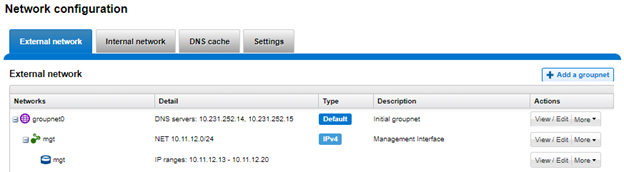
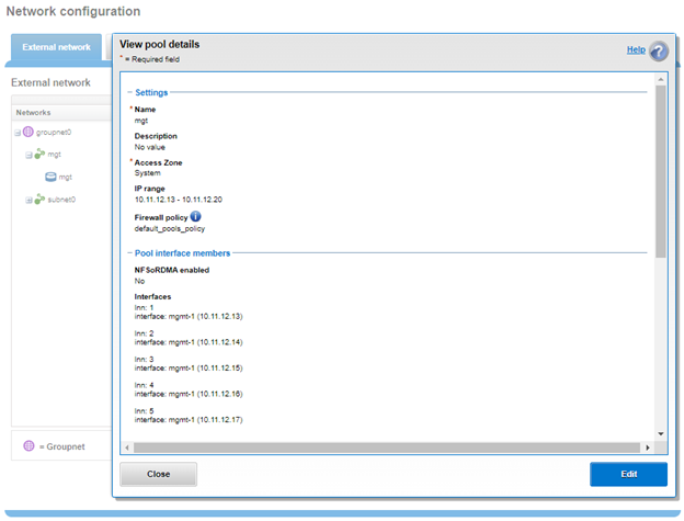
| Firewall | Host-based firewall, permitting restriction of the management interface to a dedicated subnet and hosts to specified IP pools. |
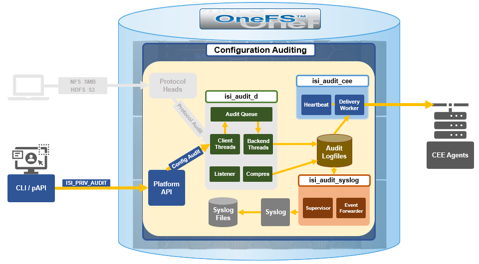
| Audit | OneFS system configuration auditing via CEE. |
| Authentication | Multifactor authentication (MFA), single sign-on (SSO) through SAML for the WebUI, and PKI-based authentication. |
| HTTP | HTTP Service Separation. |
| IPv6 | IPV6-only network support for the USGv6R1 standard. |
| Restricted Shell | Secure shell with limited access to cluster command line utilities. Eliminates areas where commands and scripts could be run and files modified maliciously and unaudited. |
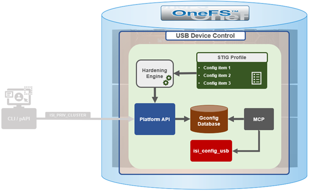
While these features and tools can be activated, configured, and controlled manually, they can also be enabled automatically by a OneFS security policy, under the purview of the OneFS Hardening Engine.
While security hardening has been a salient part of OneFS since 7.2.1, the underlying infrastructure saw a significant redesign and augmentation in OneFS 9.5. A primary motivation for this overhaul was to comply with the current stringent US Federal security mandates and ready PowerScale for inclusion in the Department of Defense Information Networks (DoDIN) Approved Product List (APL). Specifically, compliance with the applicable DoD Security Requirements Guides (SRGs) and Security Technical Implementation Guides (STIGs).
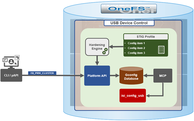
While retaining its legacy functionality, the enhanced security hardening functionality in OneFS 9.5 enhances both scope, scale, and accountability. The basic hardening architecture is as follows:
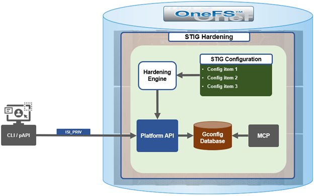
When hardening is activated, the security hardening engine reads the STIG configuration from its config files. Sets of rules, or config items, are applied to the hardening configuration to increase security and/or ensure STIG compliance. These rules are grouped by profile, which contain collections of named rules. Profiles are now stored in separate .xml files under /etc/isi_hardening/profiles.
# ls /etc/isi_hardening/profiles

profile_root-lockdown.xml       profile_stig.xml
As of OneFS 9.12, there are two profile available – STIG and Root Lockdown Mode (RLM) – and the infrastructure is in place to support additional profiles as an when they are required.
Similarly, the individual rules are stored in separate .xml files under /etc/isi_hardening/rules.
# ls /etc/isi_hardening/rules
rules_apache.xml rules_celog.xml rules_root.xml
rules_audit.xml rules_fips.xml rules_shell_timeout.xml
rules_auth.xml rules_misc.xml rules_umask.xml
rules_banners.xml rules_password.xml
rules_cacpiv.xml rules_pki_ocsp.xml
These rules are grouped by functional area affected (as opposed to by release in earlier versions), and can now apply to platform API configuration ‘collections’. For example, a rule can be applied to all NFS exports or all SyncIQ policies. In addition to actionable rules, ‘check-only’ rules are supported which apply no changes.
The new rules in OneFS 9.5 and later are also smarter, and now allow comparator logic in addition to the previous equality. For example, the new rules can evaluate conditions like whether a string is empty or non-empty, and if a given timeout is greater or equal to the required value.
Examples of STIG hardening rules include:
| Functional Area | Rule Description |
| Firewall | Enables the OneFS firewall. |
| WebUI | Forces the OneFS WebUI to listen on a specific IP address. |
| Restricted Shell | Enforces the use of the restricted shell. |
| WebDAV | Disables WebDAV HTTP filesystem access. |
| SyncIQ | Enabling encrypted transport for all SyncIQ replication policies. |
For example:
# cat /etc/isi_hardening/profile_stig.xml

<?xml version="1.0" encoding="UTF-8"?>

<Profiles version="1">

    <Profile>

        <Name>STIG</Name>

        <Description>Enable all STIG security settings</Description>

        <Rule>set_celog_snmp_use_fips</Rule>

        <Rule>disable_supportassist</Rule>

        <Rule>disable_usb_ports</Rule>

        <Rule>disable_ndmpd</Rule>

        <Rule>enable_smtp_ssl</Rule>

        <Rule>enable_onefs_cli</Rule>

        <Rule>set_min_password_percent_of_characters_changed</Rule>

        <Rule>set_ads_ldap_sign_and_seal</Rule>

        <Rule>set_ads_ldap_sign_and_seal_default</Rule>

        <Rule>set_ads_machine_password_changes</Rule>

        <Rule>limit_ads_machine_password_lifespan</Rule>

        <Rule>enable_firewall</Rule>

        <Rule>disable_audit_log_delete</Rule>

        <Rule>set_audit_retention_period</Rule>

        <Rule>disable_webui_access_ran</Rule>

        <Rule>set_ssh_config_client_alive_interval</Rule>

        <Rule>set_ssh_config_client_alive_count</Rule>

        <Rule>set_nfs_security_flavors</Rule>

<Snip>
Several enhancements have been made to the hardening engine in OneFS 9.5 and later, the most notable of which is a significant increase in the number of rules permitted. The hardening engine also now includes a reporting component, allowing detailed reports to be generated that indicate which hardening rules are applied or not, as well as overall compliance status. For example:
# isi hardening reports create

...............Hardening operation complete.

# isi hardening reports list

Name  Applied  Status        Creation Date            Report Age

-----------------------------------------------------------------

STIG  No       Compliant Sat Apr 22 04:28:40 2023 2m1s

-----------------------------------------------------------------

Total: 1

# isi hardening reports view STIG | more

Name                              Location  Status      Setting

----------------------------------------------------------------------------------------------

logout_zsh_clear_screen           Node 8    Applied /etc/zlogout

logout_profile_clear_screen       Node 8    Applied /etc/profile

logout_csh_clear_screen           Node 8    Applied /etc/csh.logout

require_password_single_user_mode Node 8    Not Applied /etc/ttys

set_password_min_length_pam_01    Node 8    Not Applied /etc/pam.d/system

set_password_min_length_pam_02    Node 8    Not Applied /etc/pam.d/other

set_password_min_length_pam_03    Node 8    Not Applied /etc/pam.d/passwd

set_password_min_length_pam_04    Node 8    Not Applied /etc/pam.d/passwd

disable_apache_proxy              Node 8    Not Applied /etc/mcp/templates/isi_data_httpd.conf

disable_apache_proxy              Node 8    Not Applied /etc/mcp/templates/isi_data_httpd.conf

disable_apache_proxy              Node 8    Not Applied /etc/mcp/templates/isi_data_httpd.conf

set_shell_timeout_01              Node 8    Not Applied /etc/profile

set_shell_timeout_02              Node 8    Applied     /etc/zshrc

set_shell_timeout_03              Node 8    Not Applied /etc/zshrc

set_shell_timeout_04              Node 8    Not Applied /etc/csh.cshrc

set_dod_banner_02                 Node 8    Not Applied symlink:/etc/issue

check_node_default_umask          Node 8    Applied     umask

logout_zsh_clear_screen           Node 40   Not Applied /etc/zlogout

logout_profile_clear_screen       Node 40   Not Applied /etc/profile

logout_csh_clear_screen           Node 40   Not Applied /etc/csh.logout

require_password_single_user_mode Node 40   Not Applied /etc/ttys

--More—(byte 2185)
These reports can be generated regardless of cluster hardening status.
OneFS security hardening comes pre-installed, but not activated by default, on a PowerScale cluster, and hardening cannot be uninstalled. Hardening is a licensed feature, and there are no changes to the licensing requirements or structure for OneFS 9.5 and later.
If a current license is not available, the following warning will be returned when attempting to activate security hardening on a cluster:
# isi hardening apply STIG

The HARDENING application is not currently installed. Please contact your Isilon account team for more information on evaluating and purchasing HARDENING.
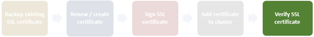
Applying a hardening profile is one of multiple steps required in order to configure a STIG-compliant PowerScale cluster. In the next article in this series we’ll cover the configuration and activation of OneFS security hardening.