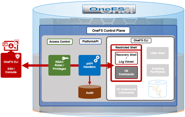
Complementary to the restricted shell itself, which was covered in the previous article in this series, OneFS 9.5 also sees the addition of a new log viewer, plus a recovery shell option.
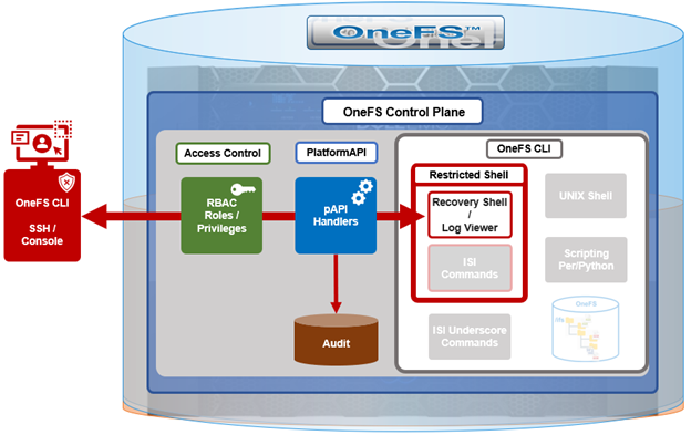
The new isi_log_access CLI utility enables a secure shell user to read, page, and query the logfiles in the /var/log directory. The ability to run this tool is governed by user’s role being granted the ‘ISI_PRIV_SYS_SUPPORT’ role-based access control (RBAC) privilege.
OneFS RBAC is used to explicitly limit who has access to the range of cluster configurations and operations. This granular control allows administrative roles to be crafted which can create and manage the various OneFS core components and data services, isolating each to specific security roles or to admin only, etc.
In this case, a cluster security administrator selects the desired multi-tenant access zone, creates a zone-aware role within it, assigns the ‘ISI_PRIV_SYS_SUPPORT’ privileges, for isi_log_access use, and then assigns users to the role.
Note that the built-in OneFS ‘AuditAdmin’ RBAC role does not contains the ‘ISI_PRIV_SYS_SUPPORT’ by default. Also, the built-in RBAC roles cannot be reconfigured:
# isi auth roles modify AuditAdmin --add-priv=ISI_PRIV_SYS_SUPPORT

The privileges of built-in role AuditAdmin cannot be modified
Therefore, the ‘ISI_PRIV_SYS_SUPPORT’ role will need to be added to a custom role.
For example, the following CLI syntax will add the user ‘usr_admin_restricted’ to the ‘rl_ssh’ role, and add the privilege ‘ISI_PRIV_SYS_SUPPORT’ to the ‘rl_ssh’ role:
# isi auth roles modify rl_ssh --add-user=usr_admin_restricted

# isi auth roles modify rl_ssh --add-priv=ISI_PRIV_SYS_SUPPORT

# isi auth roles view rl_ssh
       Name: rl_ssh
Description: -
    Members: u_ssh_restricted
             u_admin_restricted
 Privileges
             ID: ISI_PRIV_LOGIN_SSH
     Permission: r

             ID: ISI_PRIV_SYS_SUPPORT
     Permission: r
The ‘usr_admin_restricted’ user can also be added to the ‘AuditAdmin’ role, if desired:
# isi auth roles modify AuditAdmin --add-user=usr_admin_restricted

# isi auth roles view AuditAdmin | grep -i member
    Members: usr_admin_restricted
So the isi_log_access tool itself supports the following command options and arguments:
| Option |
Description |
| –grep |
Match a pattern against the file and display on stdout. |
| –help |
Displays the command description and usage message. |
| –list |
List all the files in the /var/log tree. |
| –less |
Display the file on stdout with a pager in secure_mode. |
| –more |
Display the file on stdout with a pager in secure_mode. |
| –view |
Display the file on stdout. |
| –watch |
Display the end of the file and new content as it is written. |
| –zgrep |
Match a pattern against the unzipped file contents and display on stdout. |
| –zview |
Display an unzipped version of the file on stdout. |
Here the ‘u_admin_restricted’ user logs in to the secure shell and runs the isi_log_access utility to list the /var/log/messages logfile:
# ssh u_admin_restricted@10.246.178.121
(u_admin_restricted@10.246.178.121) Password:
Last login: Wed May  3 18:02:18 2023 from 10.246.159.107
Copyright (c) 2001-2023 Dell Inc. or its subsidiaries. All Rights Reserved.
Copyright (c) 1992-2018 The FreeBSD Project.
Copyright (c) 1979, 1980, 1983, 1986, 1988, 1989, 1991, 1992, 1993, 1994
        The Regents of the University of California. All rights reserved.

PowerScale OneFS 9.5.0.0

Allowed commands are
        clear ...
        isi ...
        isi_recovery_shell ...
        isi_log_access ...
        exit
        logout
# isi_log_access --list
LAST MODIFICATION TIME         SIZE       FILE
Mon Apr 10 14:22:18 2023       56         alert.log
Fri May  5 00:30:00 2023       62         all.log
Fri May  5 00:30:00 2023       99         all.log.0.gz
Fri May  5 00:00:00 2023       106        all.log.1.gz
Thu May  4 00:30:00 2023       100        all.log.2.gz
Thu May  4 00:00:00 2023       107        all.log.3.gz
Wed May  3 00:30:00 2023       99         all.log.4.gz
Wed May  3 00:00:00 2023       107        all.log.5.gz
Tue May  2 00:30:00 2023       100        all.log.6.gz
Mon Apr 10 14:22:18 2023       56         audit_config.log
Mon Apr 10 14:22:18 2023       56         audit_protocol.log
Fri May  5 17:23:53 2023       82064      auth.log
Sat Apr 22 12:09:31 2023       10750      auth.log.0.gz
Mon Apr 10 15:31:36 2023       0          bam.log
Mon Apr 10 14:22:18 2023       56         boxend.log
Mon Apr 10 14:22:18 2023       56         bwt.log
Mon Apr 10 14:22:18 2023       56         cloud_interface.log
Mon Apr 10 14:22:18 2023       56         console.log
Fri May  5 18:20:32 2023       23769      cron
Fri May  5 15:30:00 2023       8803       cron.0.gz
Fri May  5 03:10:00 2023       9013       cron.1.gz
Thu May  4 15:00:00 2023       8847       cron.2.gz
Fri May  5 03:01:02 2023       3012       daily.log
Fri May  5 00:30:00 2023       101        daily.log.0.gz
Fri May  5 00:00:00 2023       1201       daily.log.1.gz
Thu May  4 00:30:00 2023       102        daily.log.2.gz
Thu May  4 00:00:00 2023       1637       daily.log.3.gz
Wed May  3 00:30:00 2023       101        daily.log.4.gz
Wed May  3 00:00:00 2023       1200       daily.log.5.gz
Tue May  2 00:30:00 2023       102        daily.log.6.gz
Mon Apr 10 14:22:18 2023       56         debug.log
Tue Apr 11 12:29:37 2023       3694       diskpools.log
Fri May  5 03:01:00 2023       244566     dmesg.today
Thu May  4 03:01:00 2023       244662     dmesg.yesterday
Tue Apr 11 11:49:32 2023       788        drive_purposing.log
Mon Apr 10 14:22:18 2023       56         ethmixer.log
Mon Apr 10 14:22:18 2023       56         gssd.log
Fri May  5 00:00:35 2023       41641      hardening.log
Mon Apr 10 15:31:05 2023       17996      hardening_engine.log
Mon Apr 10 14:22:18 2023       56         hdfs.log
Fri May  5 15:51:28 2023       31359      hw_ata.log
Fri May  5 15:51:28 2023       56527      hw_da.log
Mon Apr 10 14:22:18 2023       56         hw_nvd.log
Mon Apr 10 14:22:18 2023       56         idi.log
In addition to parsing an entire logfile with the ‘more’ and ‘less’ flags , the isi_log_access utility can also be used to watch (ie. ‘tail’) a log. For example, the /var/log/messages logfile:
% isi_log_access --watch messages
2023-05-03T18:00:12.233916-04:00 <1.5> h7001-2(id2) limited[68236]: Called ['/usr/bin/isi_log_access', 'messages'], which returned 2.
2023-05-03T18:00:23.759198-04:00 <1.5> h7001-2(id2) limited[68236]: Calling ['/usr/bin/isi_log_access'].
2023-05-03T18:00:23.797928-04:00 <1.5> h7001-2(id2) limited[68236]: Called ['/usr/bin/isi_log_access'], which returned 0.
2023-05-03T18:00:36.077093-04:00 <1.5> h7001-2(id2) limited[68236]: Calling ['/usr/bin/isi_log_access', '--help'].
2023-05-03T18:00:36.119688-04:00 <1.5> h7001-2(id2) limited[68236]: Called ['/usr/bin/isi_log_access', '--help'], which returned 0.
2023-05-03T18:02:14.545070-04:00 <1.5> h7001-2(id2) limited[68236]: Command not in list of allowed commands.
2023-05-03T18:02:50.384665-04:00 <1.5> h7001-2(id2) limited[68594]: Calling ['/usr/bin/isi_log_access', '--list'].
2023-05-03T18:02:50.440518-04:00 <1.5> h7001-2(id2) limited[68594]: Called ['/usr/bin/isi_log_access', '--list'], which returned 0.
2023-05-03T18:03:13.362411-04:00 <1.5> h7001-2(id2) limited[68594]: Command not in list of allowed commands.
2023-05-03T18:03:52.107538-04:00 <1.5> h7001-2(id2) limited[68738]: Calling ['/usr/bin/isi_log_access', '--watch', 'messages'].
As expected, the last few lines of the messages logfile are displayed. These log entries include the command audit entries for the ‘usr_admin_secure’ user running the ‘isi_log_access’ utility with both the ‘—-help’, ‘–list’, and ‘—-watch’ arguments.
The ‘isi_log_access’ utility also allows zipped logfiles to be read (–zview) or searched (–zgrep) without uncompressing them. For example, to find all the ‘usr_admin’ entries in the zipped vmlog.0.gz file:
# isi_log_access --zgrep usr_admin vmlog.0.gz
   0.0 64468 usr_admin_restricted /usr/local/bin/zsh
   0.0 64346 usr_admin_restricted python /usr/local/restricted_shell/bin/restricted_shell.py (python3.8)
   0.0 64468 usr_admin_restricted /usr/local/bin/zsh
   0.0 64346 usr_admin_restricted python /usr/local/restricted_shell/bin/restricted_shell.py (python3.8)
   0.0 64342 usr_admin_restricted sshd: usr_admin_restricted@pts/3 (sshd)
   0.0 64331 root               sshd: usr_admin_restricted [priv] (sshd)
   0.0 64468 usr_admin_restricted /usr/local/bin/zsh
   0.0 64346 usr_admin_restricted python /usr/local/restricted_shell/bin/restricted_shell.py (python3.8)
   0.0 64342 usr_admin_restricted sshd: u_admin_restricted@pts/3 (sshd)
   0.0 64331 root               sshd: usr_admin_restricted [priv] (sshd)
OneFS Recovery shell
The purpose of the recovery shell to allow a restricted shell user to access a regular UNIX shell, and its associated command set, if needed. As such, the recovery shell is primarily designed and intended for reactive cluster recovery operations, and other unforeseen support issues. Note that the ‘isi_recovery_shell’ CLI command can only be run, and the recovery shell entered, from within the restricted shell.
The ‘ISI_PRIV_RECOVERY_SHELL’ privilege is required in order for a user to elevate their shell from restricted to recovery. The following syntax can be used to add this privilege to a role, in this case the ‘rl_ssh’ role:
% isi auth roles modify rl_ssh --add-priv=ISI_PRIV_RECOVERY_SHELL

% isi auth roles view rl_ssh
       Name: rl_ssh
Description: -
    Members: usr_ssh_restricted
             usr_admin_restricted
 Privileges
             ID: ISI_PRIV_LOGIN_SSH
     Permission: r

             ID: ISI_PRIV_SYS_SUPPORT
     Permission: r

             ID: ISI_PRIV_RECOVERY_SHELL
     Permission: r
However, note that the ‘–-restricted-shell-enabled’ security parameter must be set to ‘true’ before a user with the ISI_PRIV_RECOVERY_SHELL privilege can actually enter the recovery shell. For example:
% isi security settings view | grep -i restr

Restricted shell Enabled: No

% isi security settings modify –restricted-shell-enabled=true

% isi security settings view | grep -i restr

Restricted shell Enabled: Yes
The restricted shell user will need to enter the cluster’s root password in order to successfully enter the recovery shell. For example:
% isi_recovery_shell -h
Description:
        This command is used to enter the Recovery shell i.e. normal zsh shell from the PowerScale Restricted shell. This command is supported only in the PowerScale Restricted shell.

Required Privilege:
        ISI_PRIV_RECOVERY_SHELL

Usage:
        isi_recovery_shell
           [{--help | -h}]
If root password is entered incorrectly, the following error will be displayed:
% isi_recovery_shell
Enter 'root' credentials to enter the Recovery shell
Password:
Invalid credentials.
isi_recovery_shell: PAM Auth Failed
A successful recovery shell launch is as follows:
$ ssh u_admin_restricted@10.246.178.121
(u_admin_restricted@10.246.178.121) Password:
Last login: Thu May  4 17:26:10 2023 from 10.246.159.107
Copyright (c) 2001-2023 Dell Inc. or its subsidiaries. All Rights Reserved.
Copyright (c) 1992-2018 The FreeBSD Project.
Copyright (c) 1979, 1980, 1983, 1986, 1988, 1989, 1991, 1992, 1993, 1994
        The Regents of the University of California. All rights reserved.

PowerScale OneFS 9.5.0.0

Allowed commands are
        clear ...
        isi ...
        isi_recovery_shell ...
        isi_log_access ...
        exit
        logout

% isi_recovery_shell
Enter 'root' credentials to enter the Recovery shell
Password:
%
At this point, regular shell/UNIX commands (including the ‘vi’ editor) are available again:
% whoami
u_admin_restricted

% pwd
/ifs/home/u_admin_restricted
% top | head -n 10
last pid: 65044;  load averages:  0.12,  0.24,  0.29  up 24+04:17:23    18:38:39
118 processes: 1 running, 117 sleeping
CPU:  0.1% user,  0.0% nice,  0.9% system,  0.1% interrupt, 98.9% idle
Mem: 233M Active, 19G Inact, 2152K Laundry, 137G Wired, 60G Buf, 13G Free
Swap:
  PID USERNAME    THR PRI NICE   SIZE    RES STATE    C   TIME    WCPU COMMAND
 3955 root          1 -22  r30    50M    14M select  24 142:28   0.54% isi_drive_d
 5715 root         20  20    0   231M    69M kqread   5  55:53   0.15% isi_stats_d
 3864 root         14  20    0    81M    21M kqread  16 133:02   0.10% isi_mcp
The specifics of the recovery shell (ZSH) for the u_admin_restricted user are reported as follows:
% printenv $SHELL
_=/usr/bin/printenv
PAGER=less
SAVEHIST=2000
HISTFILE=/ifs/home/u_admin_restricted/.zsh_history
HISTSIZE=1000
OLDPWD=/ifs/home/u_admin_restricted
PWD=/ifs/home/u_admin_restricted
SHLVL=1
LOGNAME=u_admin_restricted
HOME=/ifs/home/u_admin_restricted
RECOVERY_SHELL=TRUE
TERM=xterm
PATH=/sbin:/bin:/usr/sbin:/usr/bin:/usr/local/sbin:/usr/local/bin:/root/bin
Shell logic conditions and scripts can be run. For example:
% while true; do uptime; sleep 5; done
 5:47PM  up 24 days,  3:26, 5 users, load averages: 0.44, 0.38, 0.34
 5:47PM  up 24 days,  3:26, 5 users, load averages: 0.41, 0.38, 0.34
ISI commands can be run and cluster management tasks performed.
% isi hardening list
Name  Description                       Status
---------------------------------------------------
STIG  Enable all STIG security settings Not Applied
---------------------------------------------------
Total: 1
For example, creating and deleting a snapshot:
% isi snap snap list
ID Name Path
------------
------------
Total: 0


% isi snap snap create /ifs/data

% isi snap snap list
ID   Name  Path
--------------------
2    s2    /ifs/data
--------------------
Total: 1

% isi snap snap delete 2
Are you sure? (yes/[no]): yes
Sysctls can be read and managed:
% sysctl efs.gmp.group

efs.gmp.group: <10539754> (4) :{ 1:0-14, 2:0-12,14,17, 3-4:0-14, smb: 1-4, nfs: 1-4, all_enabled_protocols: 1-4, isi_cbind_d: 1-4, lsass: 1-4, external_connectivity: 1-4 }
The restricted shell can be disabled:
% isi security settings modify --restricted-shell-enabled=false

% isi security settings view | grep -i restr
Restricted shell Enabled: No
However, the ‘isi underscore’ (isi_*) commands, such as isi_for_array, are still not permitted to run:
% /usr/bin/isi_for_array -s uptime
zsh: permission denied: /usr/bin/isi_for_array

% isi_gather_info
zsh: permission denied: isi_gather_info

% isi_cstats
isi_cstats: Syscall ifs_prefetch_lin() failed: Operation not permitted
When finished, the user can either end the session entirely with the ‘logout’ command, or quit the recovery shell via ‘exit’ and return to the restricted shell:
% exit

Allowed commands are

        clear ...
        isi ...
        isi_recovery_shell ...
        isi_log_access ...
        exit
        logout
%