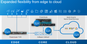
In this article, we’ll take a quick peek at the new PowerScale F900 hardware platform that was released last week. Here’s where this new node sits in the current PowerScale hardware hierarchy:
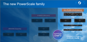
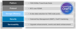
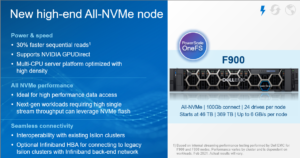
The PowerScale F900 is a high-end all-flash platform that utilizes NVMe SSDs and a dual-CPU 2U PowerEdge platform with 736GB of memory per node. The ideal use cases for the F900 include high performance workflows, such as M&E, EDA, AI/ML, and other HPC applications and next gen workloads.
An F900 cluster can comprise between 3 and 252 nodes, each of which contains twenty four 2.5” drive bays populated with a choice of 1.92TB, 3.84TB, 7,68TB, or 15.36TB enterprise NVMe SSDs, and netting up to 181TB of RAM and 91PB of all-flash storage per cluster. Inline data reduction, which incorporates compression, dedupe, and single instancing, is also included as standard to further increase the effective capacity.
The F900 is based on the 2U Dell R740 PowerEdge server platform, with dual socket Intel CPUs, as follows:
| Description | PowerScale F900
(PE R740xd platform w/ NVMe SSDs) |
| Minimum # of nodes in a cluster | 3 |
| Raw capacity per minimum sized cluster (3 nodes) | 138TB to 1080TB
Drive capacity options: 1.92 TB, 3.82 TB, 7.68 TB, or 15.36 TB |
| SSD Drives in min. sized cluster | 24 x 3 = 72 |
| Rack Unit (RU) per min. cluster | 6 RU |
| Processor | Dual socket Intel Xeon Processor Gold 6240R (2.2GHz, 24C) |
| Memory per node | 736 GB per node |
| Front-End Connectivity | 2 x 10/25GbE or 2 x 40/100GbE |
| Back-end Connectivity | 2 x 40/100GbE or
2 x QDR Infiniband (IB) for interoperability to previous generation clusters |
Or, as reported by OneFS:
# isi_hw_status -ic
SerNo: 5FH9K93
Config: PowerScale F900
ChsSerN: 5FH9K93
ChsSlot: n/a
FamCode: F
ChsCode: 2U
GenCode: 00
PrfCode: 9
Tier: 7
Class: storage
Series: n/a
Product: F900-2U-Dual-736GB-2x100GE QSFP+-45TB SSD
HWGen: PSI
Chassis: POWEREDGE (Dell PowerEdge)
CPU: GenuineIntel (2.39GHz, stepping 0x00050657)
PROC: Dual-proc, 24-HT-core
RAM: 789523222528 Bytes
Mobo: 0YWR7D (PowerScale F900)
NVRam: NVDIMM (NVDIMM) (8192MB card) (size 8589934592B)
DskCtl: NONE (No disk controller) (0 ports)
DskExp: None (No disk expander)
PwrSupl: PS1 (type=AC, fw=00.1D.7D)
PwrSupl: PS2 (type=AC, fw=00.1D.7D)
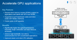
The F900 nodes are available in two networking configurations, with either a 10/25GbE or 40/100GbE front-end, plus a standard 100GbE or QDR Infiniband back-end for each.
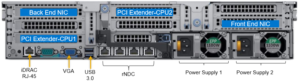
The 40G and 100G connections are actually four lanes of 10G and 25G respectively, allowing switches to ‘breakout’ a QSFP port into 4 SFP ports. While this is automatic on the Dell back-end switches, some front-end switches may need configuring.
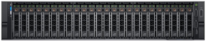
Drive subsystem-wise, the PowerScale F900 has twenty four total drive bays spread across the front of the chassis:
Under the hood on the F900, OneFS provides support NVMe across PCIe lanes, and the SSDs use the NVMe and NVD drivers. The NVD is a block device driver that exposes an NVMe namespace like a drive and is what most OneFS operations act upon, and each NVMe drive has a /dev/nvmeX, /dev/nvmeXnsX and /dev/nvdX device entry and the locations are displayed as ‘bays’. Details can be queried with OneFS CLI drive utilities such as ‘isi_radish’ and ‘isi_drivenum’. For example:
# isi devices drive list
Lnn Location Device Lnum State Serial
------------------------------------------------------
1 Bay 0 /dev/nvd15 9 HEALTHY S61DNE0N702037
1 Bay 1 /dev/nvd14 10 HEALTHY S61DNE0N702480
1 Bay 2 /dev/nvd13 11 HEALTHY S61DNE0N702474
1 Bay 3 /dev/nvd12 12 HEALTHY S61DNE0N702485
1 Bay 4 /dev/nvd19 5 HEALTHY S61DNE0N702031
1 Bay 5 /dev/nvd18 6 HEALTHY S61DNE0N702663
1 Bay 6 /dev/nvd17 7 HEALTHY S61DNE0N702726
1 Bay 7 /dev/nvd16 8 HEALTHY S61DNE0N702725
1 Bay 8 /dev/nvd23 1 HEALTHY S61DNE0N702718
1 Bay 9 /dev/nvd22 2 HEALTHY S61DNE0N702727
1 Bay 10 /dev/nvd21 3 HEALTHY S61DNE0N702460
1 Bay 11 /dev/nvd20 4 HEALTHY S61DNE0N700350
1 Bay 12 /dev/nvd3 21 HEALTHY S61DNE0N702023
1 Bay 13 /dev/nvd2 22 HEALTHY S61DNE0N702162
1 Bay 14 /dev/nvd1 23 HEALTHY S61DNE0N702157
1 Bay 15 /dev/nvd0 0 HEALTHY S61DNE0N702481
1 Bay 16 /dev/nvd7 17 HEALTHY S61DNE0N702029
1 Bay 17 /dev/nvd6 18 HEALTHY S61DNE0N702033
1 Bay 18 /dev/nvd5 19 HEALTHY S61DNE0N702478
1 Bay 19 /dev/nvd4 20 HEALTHY S61DNE0N702280
1 Bay 20 /dev/nvd11 13 HEALTHY S61DNE0N702166
1 Bay 21 /dev/nvd10 14 HEALTHY S61DNE0N702423
1 Bay 22 /dev/nvd9 15 HEALTHY S61DNE0N702483
1 Bay 23 /dev/nvd8 16 HEALTHY S61DNE0N702488
------------------------------------------------------
Total: 24
Or for the details of a particular drive:
# isi devices drive view 15
Lnn: 1
Location: Bay 15
Lnum: 0
Device: /dev/nvd0
Baynum: 15
Handle: 346
Serial: S61DNE0N702481
Model: Dell Ent NVMe AGN RI U.2 1.92TB
Tech: NVME
Media: SSD
Blocks: 3750748848
Logical Block Length: 512
Physical Block Length: 512
WWN: 363144304E7024810025384500000003
State: HEALTHY
Purpose: STORAGE
Purpose Description: A drive used for normal data storage operation
Present: Yes
Percent Formatted: 100
# isi_radish -a /dev/nvd0

Bay 15/nvd0   is Dell Ent NVMe AGN RI U.2 1.92TB FW:2.0.2 SN:S61DNE0N702481, 3750748848 blks

Log Sense data (Bay 15/nvd0  ) --

Supported log pages 0x1 0x2 0x3 0x4 0x5 0x6 0x80 0x81

SMART/Health Information Log

============================

Critical Warning State:         0x00

 Available spare:               0

 Temperature:                   0

 Device reliability:            0

 Read only:                     0

 Volatile memory backup:        0

Temperature:                    310 K, 36.85 C, 98.33 F

Available spare:                100

Available spare threshold:      10

Percentage used:                0

Data units (512,000 byte) read: 3804085

Data units written:             96294

Host read commands:             29427236

Host write commands:            480646

Controller busy time (minutes): 7

Power cycles:                   36

Power on hours:                 774

Unsafe shutdowns:               31

Media errors:                   0

No. error info log entries:     0

Warning Temp Composite Time:    0

Error Temp Composite Time:      0

Temperature Sensor 1:           310 K, 36.85 C, 98.33 F

Temperature 1 Transition Count: 0

Temperature 2 Transition Count: 0

Total Time For Temperature 1:   0

Total Time For Temperature 2:   0

SMART status is threshold NOT exceeded (Bay 15/nvd0  )

Error Information Log

=====================

No error entries found
The F900 nodes’ front panel has limited functionality compared to older platform generations and will simply allow the user to join a node to a cluster and display the node name after the node has successfully joined the cluster.
Similar to legacy Gen6 platforms, a PowerScale node’s serial number can be found either by viewing /etc/isilon_serial_number or running the ‘isi_hw_status | grep SerNo’ CLI command syntax. The serial number reported by OneFS will match that of the service tag attached to the physical hardware and the /etc/isilon_system_config file will report the appropriate node type. For example:
# cat /etc/isilon_system_config

PowerScale F900