Among the array of PowerScale’s core unstructured data protocols lies the AWS S3 API – arguably the gold standard for object protocols. This enables the PowerScale data lake to natively support workloads which both write data via file protocols such as NFS, HDFS or SMB, and then read that same data as S3 objects, and vice versa.
Since OneFS S3 objects and buckets are essentially files and directories at the file system level, the same PowerScale data services, such as snapshots, replication, WORM immutability, tiering, etc, are all seamlessly integrated. So too are identity and permissions management and access controls across both the file and object realms.
This means that applications and workloads have multiple access options – across both file and object, and with the same underlying dataset, semantics, and services. This has the considerable benefit of eliminating the need for replication or migration of data for different access requirements, thereby vastly simplifying data and workload management. OneFS supports HTTPS/TLS, to meet organizations’ security, in-flight encryption, and compliance needs. Additionally, since S3 is integrated into OneFS as a top-tier protocol, it offers a high level of performance, similar to that of the SMB protocol.
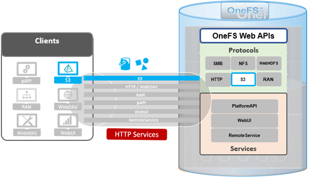
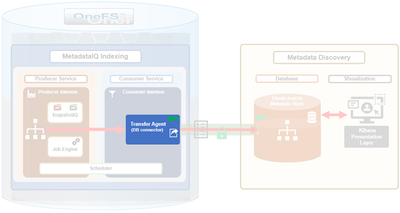
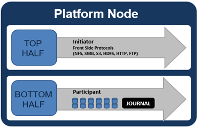
By default, the S3 service listens on port 9020 for HTTP and 9021 for HTTPS, although both these ports are easily configurable. Within a PowerScale cluster, OneFS runs on and across all nodes equally, so no one node controls or ‘masters’ the cluster and all nodes are true peers. Looking from a high-level at the components within each node, the I/O stack is split into a top layer, or initiator, and a bottom layer, or participant. This division is used as a logical model for the analysis of OneFS’ read and write paths.
At a physical-level, the CPUs and memory cache within the nodes simultaneously handle both initiator and participant tasks for I/O taking place throughout the cluster.
For clarity’s sake, the level of detail that includes the caches and distributed lock manager has been omitted from the above.
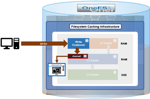
When a client connects to a node’s protocol head to perform a write, it is interacting with the logical ‘top half’, or initiator, of that node. Any files or objects that are written by the client are broken into smaller logical chunks, or stripes, before being written to the logical ‘bottom half’, or participant, of a node, where the storage drives reside. Failure-safe buffering (write coalescer and journal) ensures that writes are efficient and read-modify-write operations are avoided. OneFS stripes data across all nodes and protects the files, directories and associated metadata via software erasure-code or mirroring.
File and object locking allows multiple users or processes to access data via a variety of protocols concurrently and safely. Since all nodes in an PowerScale cluster operate on the same single-namespace file system simultaneously, it requires mutual exclusion mechanisms to function correctly. For reading data, this is a fairly straightforward process involving shared locks. With writes, however, things become more complex and require exclusive locking, since data must be kept consistent.
Under the hood, the ‘bottom half’ locks OneFS uses to provide consistency inside the file system (internal) are separate from the ‘top half’ protocol locks that manage concurrency across applications (external). This allows OneFS to move a file’s metadata and data blocks around while the file itself is locked by an application. This is the premise of OneFS auto-balancing, reprotecting and tiering, where the restriper does its work behind the scenes in small chunks to minimize disruption.
The OneFS distributed lock manager (DLM) marshals locks across all the nodes in a storage cluster, allowing for multiple lock types to support both file system locks as well as cluster-coherent protocol-level locks. The DLM distributes the lock data across all the nodes in the cluster. In a mixed cluster, the DLM also balances memory utilization so that the lower-power nodes are not bullied.
Every node in a cluster is a coordinator for locking resources. A coordinator is assigned to lockable resources based on a hashing algorithm, designed so that the coordinator almost always ends up on a different node than the initiator of the request. When a lock is requested for a file/object, it could be either a shared or exclusive lock. Read requests are typically serviced by shared locks, allowing multiple users to simultaneously access the resource, whereas exclusive locks constrain to just one user at any given moment, typically for writes.
Here’s an example of how different nodes could request a lock from the coordinator:
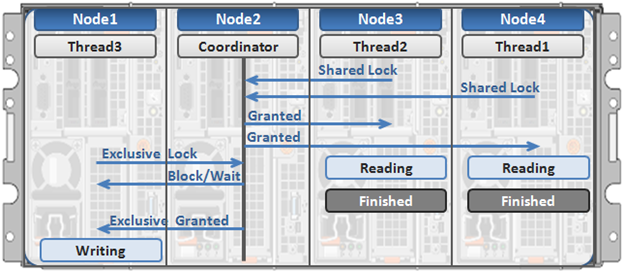
- Thread 1 from node 4 and thread 2 from node 3 simultaneously request a shared lock on a file from the coordinator on node 2.
- Since no exclusive locks exist, node 2 grants shared locks, and nodes 3 and 4 read the requested file.
- Thread 3 from node 1 requests an exclusive lock for the same file that’s being read by nodes 3 and 4.
- Nodes 3 and 4 are still reading, so the coordinator (node 2) asks thread 3 from node 1 to wait.
- Thread 3 from node 1 blocks until the exclusive lock is granted by the coordinator (node 2) and then completes its write operation.
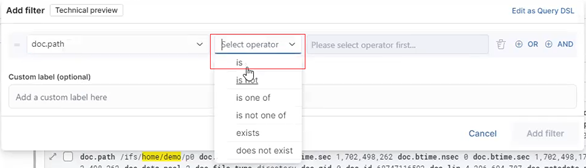
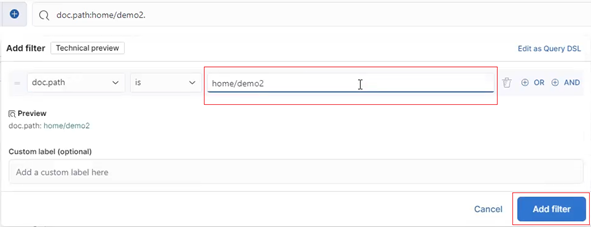
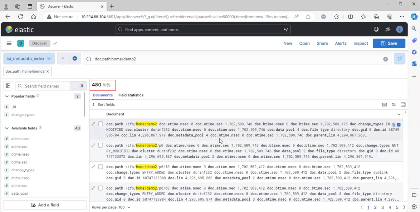
As such, an S3 client can access, read, and write to an object using HTTP GET and PUT requests, while other file protocol and/or S3 clients also access the same resource. OneFS supports two methods of specifying buckets and objects in a URL:
- Path-style requests, using the first slash-delimited component of the request-URI path. For example:
https://tme1.isilon.com:9021/bkt01/lab/object1.pdf
- Virtual hosted-style requests, specifying a bucket via the HTTP Host header. I.e.:
https://bkt01.tme.isilon.com:9021/lab/object1.pdf
Additionally, the principal API operations that OneFS supports include:
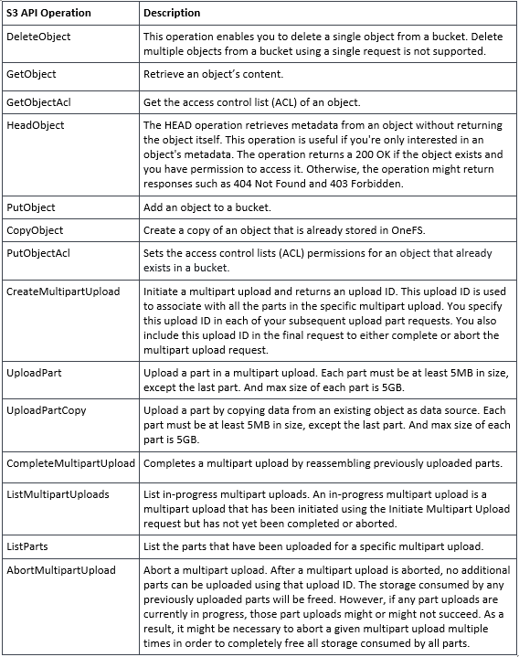
Essentially, this includes the basic bucket and object create, read, update, delete, or CRUD, operations, plus multipart upload.
As for client access, from the cluster side the general OneFS S3 operation flow can be characterized as follows:
- First, an S3 client or application establishes a connection to the cluster, with SmartConnect resolving the IP address with bucket name.
- OneFS creates a socket/listener with the appropriate TLS handling, as required.
- Next, OneFS (libLwHttp) receives and unmarshals the HTTP request/stream to determine the S3 request payload.
- Authorization and authentication is performed for bucket and object access.
- Next, the S3 request is queued for LwSched, which dispatches the work with the appropriate threading mode.
- The S3 protocol driver handles the operational logic and calls the IO manager (Lwio).
- Lwio manages any audit filter driver activity before and after the operation, while FSD (file system driver) handles the file system layer access.
- Finally, the S3 protocol driver creates an HTTP response with its operation result, which is returned to the S3 client via libLwHttp.
- Then back to step 3 for the next HTTP request, etc.
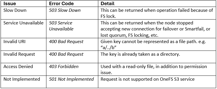
If a client HTTP request is invalid, or goes awry, OneFS follows the general AWS S3 error codes format – albeit with modifications to remove any AWS-specific info. The OneFS S3 implementation also includes some additional error codes for its intrinsic behaviors. These include:
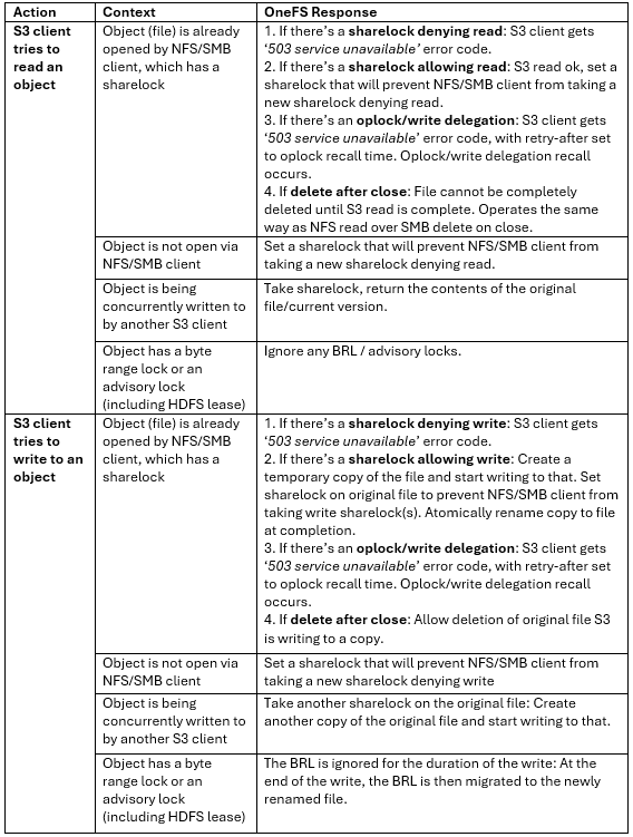
So how do things work when clients try to simultaneous access the same file/object on a cluster via both file and object protocols? Here’s the basic flow describing OneFS cross-protocol locking: