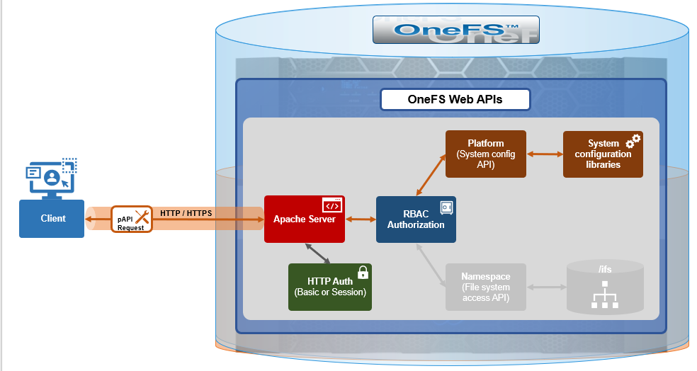
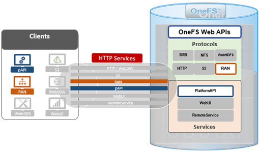
In addition to the platform API (pAPI) and RESTful access to a cluster’s namespace (RAN), OneFS makes extensive use of HTTP for a variety of services and client protocols.
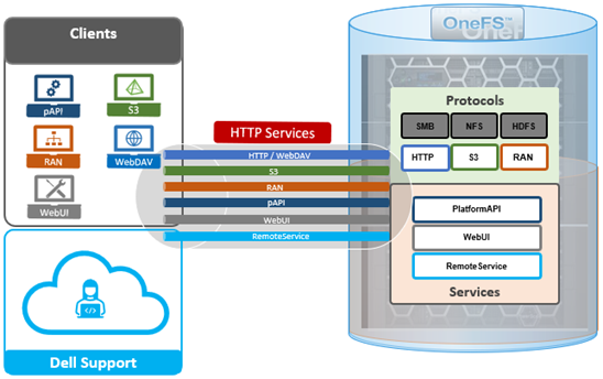
As such, OneFS also supports the following HTTP-based services:
| Service | Description | Ports |
| PlatformAPI | OneFS platform API service, for remote cluster management. | TCP 8080 |
| PowerScaleUI | OneFS WebUI configuration and management console. | TCP 8080 |
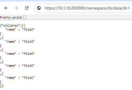
| RAN | RESTful Access to Namespace, allowing cluster data access via HTTP. | TCP 8080 |
| RemoteService | Remote-Service API handlers under the /remote-service/ namespace, managed by isi_rsapi_d. | TCP 8080 |
| S3 | AWS S3 object protocol. | TCP 9020 (http) TCP 9021 (https) |
| SWIFT | SWIFT object protocol (deprecated in favor of S3). | TCP 8083 |
| WebHDFS | WebHDFS over HTTP. | TCP 8082 |
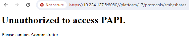
In OneFS 9.4 and later, the above HTTP services may be enabled or disabled independently via the CLI or platform API, by a user account with the ‘ISI_PRIV_HTTP RBAC’ privilege.
The ‘isi http services’ CLI command set can be used to view and modify the services HTTP services. For example, remote HTTP access to the platform API can easily be disabled as follows:
 # isi http services modify Platform-API-External --enabled=0

You are about to modify the service Platform-API-External. If you disable Platform-API-External then PowerScaleUI will also be disabled. Are you sure? (yes/[no]):
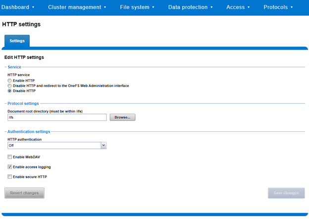
Similarly, a subset of the HTTP configuration settings, including WebDAV, can also be viewed and modified via the WebUI by navigating to Protocols > HTTP settings:
Similarly, the OneFS web services can be viewed and controlled from the CLI via the ‘isi http services’ command set. For example:
# isi http services list

ID                    Enabled

------------------------------

Platform-API-External Yes

PowerScaleUI          Yes

RAN                   Yes

RemoteService         Yes

------------------------------

Total: 4
The astute will have observed that both S3 and Swift are notably absent from the above list of OneFS HTTP services.
Since S3 has become the de facto object protocol, after a period of gradual deprecation the OpenStack Swift protocol & API has finally been completely removed in OneFS 9.9. That said, Swift will remain available and supported in OneFS 9.8 and earlier releases, until their respective end of support dates.
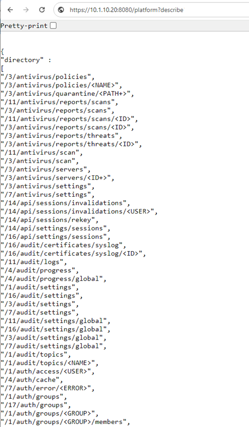
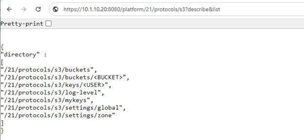
Also, while S3 service uses HTTP as its transport, it is considered as a tier-1 protocol, and as such is managed via its own ‘isi s3’ CLI command set, corresponding WebUI area, and platform API endpoints:

In the example above, the ‘?describe&list’ suffix provides all of the S3 pAPI endpoints.
Another useful facet is that the OneFS command line syntax provides a ‘—debug’ option, which displays the associated pAPI endpoint information for each CLI command entered. For example, when querying OneFS for a cluster’s storage pool info, the ‘GET [‘9’, ‘storagepool’, ‘storagepools’]’ endpoint is being used by the CLI command:
# isi --debug storagepool list

2024-08-14 07:33:01,652 DEBUG rest.py:72: >>>GET ['9', 'storagepool', 'storagepools']

2024-08-14 07:33:01,652 DEBUG rest.py:74:    args={}

   body={}

2024-08-14 07:33:01,752 DEBUG rest.py:96: <<<(200, {'status': '200 Ok', 'content-type': 'application/json', 'allow': 'GET, HEAD'}, '\n{\n"storagepools" : \n[\n\n{\n"can_disable_l3" : true,\n"can_enable_l3" : false,\n"health_flags" : [],\n"id" : 1,\n"l3" : false,\n"l3_status" : "storage",\n"lnns" : [ 1, 2, 3 ],\n"manual"

<snip>
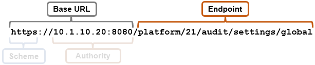
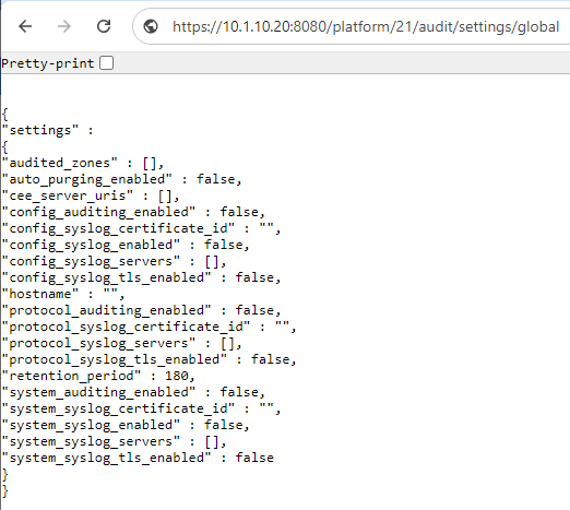
So the corresponding pAPI URL to the ‘isi storagepool storagepools list’ CLI command is:
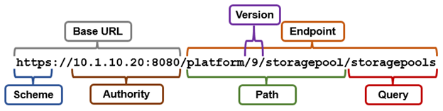
Or via curl:
# curl --insecure --basic --user <uname:passwd> https://10.1.10.20:8080/platform/9/storagepool/storagepools

{

"storagepools" :

[

{

"can_disable_l3" : true,

"can_enable_l3" : false,

"health_flags" : [],

"id" : 1,

"l3" : false,

"l3_status" : "storage",

"lnns" : [ 1, 2, 3 ],

"manual" : false,

<snip>
In addition to curl, the OneFS API endpoints can also be incorporated into script languages such as bash, perl, powershell, python, etc. This provides a powerful option for automating routine cluster management tasks.
For example, a python script along the lines of the following can be used to view a cluster’s critical events:
#!/usr/bin/python
import requests
import json
import urllib3
urllib3.disable_warnings(urllib3.exceptions.InsecureRequestWarning)
# Suppresses the self signed cert warning

CLUSTERIP = '10.1.10.20'
PORT=8080
USER='root'
PASSWD='$1cyL@wn'

uri = "https://%s:%s" % (CLUSTERIP, PORT)
papi = uri + '/platform'
headers = {'Content-Type': 'application/json'}

data = json.dumps({'username': USER, 'password': PASSWD, 'services': ['platform']})

# uri of the cluster used in the referrer header
uri = f"https://{CLUSTERIP}:{PORT}"

# url of Papi used for all further calls to Papi
papi = uri + '/platform'

# Set header as content will provided in json format
headers = {'Content-Type': 'application/json'}

# Create json dictionary for auth
data = json.dumps({'username': USER, 'password': PASSWD, 'services': ['platform']})

# create a session object to hold cookies
session = requests.Session()

# Establish session using auth credentials
response = session.post(uri + "/session/1/session", data=data, headers=headers, verify=False)

if 200 <= response.status_code < 299:
    # Set headers for CSRF protection. Without these two headers all further calls with be "auth denied"
    session.headers['referer'] = uri
    session.headers['X-CSRF-Token'] = session.cookies.get('isicsrf')
    print("Authorization Successful")
else:
    print("Authorization Failed")
    print(response.content)

endpoint = '/7/event/eventlists'
response = session.get(papi + endpoint, verify=False)
result = json.loads(response.content)

#iterate through each event in each eventlist and output only critical events
for eventlist in result['eventlists']:
    for event in eventlist['events']:
        if event['severity'] == 'critical':
            print("Event ID: %s -- Event Severity: %s -- Description: %s " % (event['event'], event['severity'], event['message']))
Note that the ‘CLUSTERIP’, ‘USER’, and ‘PASSWD’ fields in the above python script will need to be edited appropriately, to reflect a cluster’s settings.
There is also an extensive OneFS API portal and developer community:
https://www.delltechnologies.com/en-us/storage/storage-automation-and-developer-resources/index.htm
This portal provides a central location for all the Dell ecosystem integrations (plugins), including CSI drivers, VMware, Containers, DevOps, Infrastructure as Code (IaC), OpenStack, etc. It also provides community forums to collaborate, post questions, discuss ideas, share tips & tricks, etc. – in addition to code samples and ready to use integrations for developers.