In this second article in the InsightIQ 6.3 series, we’ll dig into the details of the additional functionality that debuts in this new IIQ release.
When upgrading to the new InsightIQ 6.3 release, the process is largely consistent with previous upgrades, such as InsightIQ 6.2.
The specific deployment options and hardware requirements for installing and running InsightIQ 6.x are as follows:
| Attribute | InsightIQ 6.3 Simple | InsightIQ 6.3 Scale |
| Scalability | Up to 10 clusters or 252 nodes | Up to 20 clusters or 504 nodes |
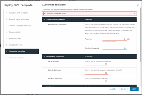
| Deployment | On VMware, using OVA template | RHEL, SLES, or Ubuntu with deployment script |
| Hardware requirements | VMware v15 or higher:
· CPU: 8 vCPU · Memory: 16GB · Storage: 1.5TB (thin provisioned); Or 500GB on NFS server datastore |
Up to 10 clusters and 252 nodes:
· CPU: 8 vCPU or Cores · Memory: 16GB · Storage: 500GB Up to 20 clusters and 504 nodes: · CPU: 12 vCPU or Cores · Memory: 32GB · Storage: 1TB |
| Networking requirements | 1 static IP on the PowerScale cluster’s subnet | 1 static IP on the PowerScale cluster’s subnet |
To initiate the upgrade to 6.3, the system must be running an InsightIQ 6.1 or 6.2 Scale or Simple deployment, plus a minimum of 40 GB of available disk space is required.
Once these prerequisites are satisfied, the upgrade process begins by extracting the InsightIQ 6.3 installer package, followed by extraction of the upgrade bundle. The upgrade is then initiated by executing the ‘upgrade-iiq.sh’ script.
Upgrade progress can be monitored using the appropriate status commands to view upgrade locks and overall status. For more detailed information, including lock details and intermediate steps, administrators can review the InsightIQ_upgrade.log file.
The InsightIQ upgrade workflow consists of five distinct stages:
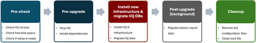
During the pre-check stage, the installer verifies the availability of required Docker commands, validates the existing InsightIQ version, checks for sufficient disk space, confirms that all InsightIQ services are running, and ensures operating system compatibility.
In the pre-upgrade stage, the installer verifies acceptance of the EULA and extracts the required InsightIQ images. The currently running InsightIQ services are then stopped, necessary directories are created, and optional containers are updated as needed.
The upgrade stage includes updating resource limits, upgrading add-on services, installing the CIM component, and upgrading the remaining InsightIQ services. The EULA is updated, followed by a final health check to confirm that all InsightIQ services are running correctly.
During the post-upgrade stage, additional steps are performed depending on the source version. For systems upgrading from InsightIQ 6.1, the Docker network is upgraded, and InsightIQ metadata is then updated.
Finally, the cleanup stage replaces outdated scripts, removes obsolete Docker images, and deletes temporary upgrade and backup directories to complete the upgrade process.
| Phase | Details |
| Pre-check | • Docker command
• InsightIQ version check 6.1.0 or 6.2.0 • Free disk space • InsightIQ services status • OS compatibility |
| Pre-upgrade | • EULA accepted
• Extract the IIQ images • Stop IIQ • Create necessary directories • Update optional containers |
| Upgrade | • Update resource limit
• Upgrade addons services • Upgrade IIQ services • Upgrade EULA • Status Check |
| Post-upgrade | • Update network (if 6.1.0)
• Update IIQ metadata |
| Cleanup | • Replace scripts
• Remove old docker images • Remove upgrade and backup folders |
Specific steps in the upgrade process are as follows:
- Download and uncompress the bundle:
# tar xvf iiq-install-6.3.0.tar.gz
- From within the InsightIQ directory, un-tar the upgrade scripts as follows:
# cd InsightIQ

# tar xvf upgrade.tar.gz
- Enter the resulting ‘upgrade’ directory which contains the scripts:
# cd upgrade/
- Initiate the IIQ upgrade. Note that the usage is same for both the Simple and Scale InsightIQ deployments.
# ./upgrade-iiq.sh -m <admin_email>
Upon successful upgrade completion, InsightIQ will be accessible via the primary node’s IP address.
Quick and easy upgrade progress checks include:
| Check | Command syntax |
| Check the latest 100 lines of upgrade log | showupg –l or showupg –log |
| Check the latest 100 lines of upgrade status | showupg –s or showupg –status |
| Check detailed logs | cat /usr/share/storagemonitoring/logs/upgrade/log/insightiq_upgrade.log |
AI-based Assistant
InsightIQ 6.3 introduces a new AI‑based Assistant. This intelligent, document‑aware AI companion is designed to help users quickly find answers, understand product capabilities, and troubleshoot issues related to InsightIQ and PowerScale. The assistant draws its responses from supported documentation, including InsightIQ and PowerScale documentation, release notes, and knowledge base articles.
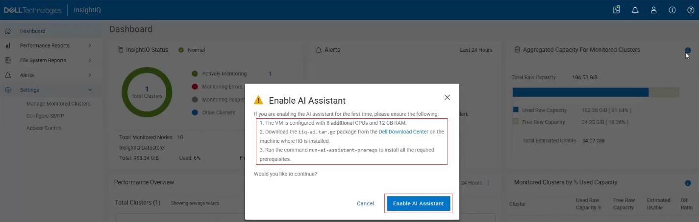
To enable the AI Assistant, several prerequisites must be met. An AI-enabled InsightIQ deployment requires an additional 8 vCPUs or cores and 12 GB of RAM above the general IIQ 6.3 spec, and a separate AI Assistant package must also be installed, which is available in the Download Center and is distinct from the standard InsightIQ Scale and Simple packages.
Note that this feature is not available in the Greater China region due to legal and regulatory restrictions, as it relies on AI models that are not permitted in that geography. Consequently, the option to enable the AI Assistant will not appear if the system is configured for the China region.
To activate the AI Assistant, users must first download the AI Assistant tar package (iiq-ai.tar.gz) from the Download Center and run the AI Assistant prerequisite command to install all required dependencies.
Note that the IIQ server resources must be updated to include the additional CPU and memory requirements as described above, after which the AI Assistant option can be enabled.
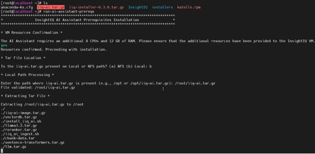
The AI assistance prerequisite installation script ‘run-ai-assistant-prereqs’ comprises four main stages:

| Stage | Description | Location |
| 1 | Push docker images | · Local registry |
| 2 | Extract models | · /usr/share/storagemonitoring/common-components/ai_models/models/reranker
· /usr/share/storagemonitoring/common-components/ai_models/models/sentence-transformer |
| 3 | Extract Llama model | · /usr/share/storagemonitoring/common-components/llm |
| 4 | Extract chunk data | · /usr/share/storagemonitoring/common-components/custom_spell_terms.json |
For example:
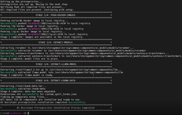
IIQ validates that all prerequisites are satisfied before launching the required containers and their respective services, including the Large Language Model (LLM), the vector database, and the InsightIQ AI Assistant controller. Once these services are running, the chatbot becomes available for use.
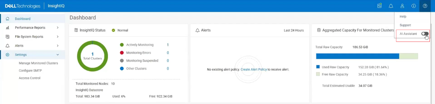
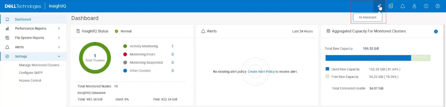
Next, the AI Assistant can be enabled from the InsightIQ masthead as follows:
The following popup window is displayed, reiterating the prerequisites and prompting to ‘Enable AI Assistant’:
At this point, assuming the prerequisites have been met, an AI Assistant button is added to the UI masthead:
Clicking this button opens the AI Assistant chat window with a ‘How can I help you today?’ prompt:
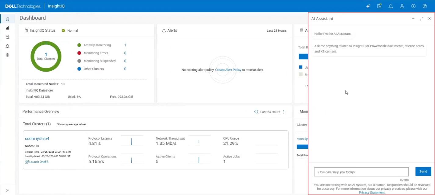
A warning is displayed noting “You are interacting with an AI system, not a human. Responses should be reviewed for accuracy.” A link is provided for more information on Dell’s Privacy Statement too.
At this point, natural language questions can be entered into the text box. For example, “how to enable dedupe in OneFS?”:
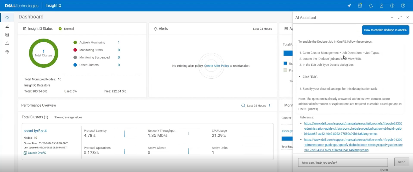
Upon clicking ‘Send’, the AI system parses the instruction and provides its best response, in this case by providing a four-step procedure for enabling OneFS deduplication, plus supporting documentation references and links.
In the next article in the InsightIQ 6.3 series, we’ll focus on the additional functionality that debuts in this new IIQ release, including:
- Support for monitoring virtual clusters deployed on AWS or Azure.
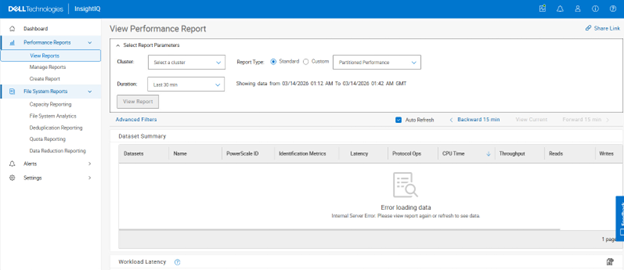
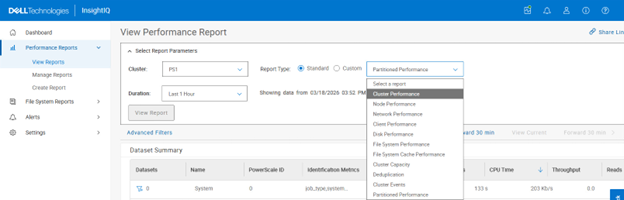
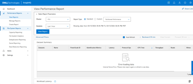
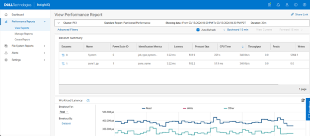
- Increased performance visibility for file and object workloads.
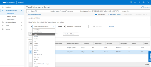
- Enhanced filtering capabilities with multiple values per category.
- Single Sign-On (SSO) support via Microsoft ADFS or Azure Entra ID.
- Direct, in-place upgrades from versions 6.1 and 6.2.