In this article I focus on how the data lakehouse architecture compares with the classic data warehouse architecture. I imagine the data lakehouse architecture as an attempt to implement some of the core requirements of data warehouse architecture in a modern, cloud-native design. I will explore the advantages of cloud-native design, including the ability to dynamically provision resources in response to specific events, predetermined patterns, and other triggers. I also explore data lakehouse architecture as its own unique approach to addressing new or different types of practices, use cases, and consumers.
In an important sense, data lakehouse architecture is an effort to adapt the data warehouse and its architecture to the cloud, while also addressing a larger set of novel use cases, practices, and consumers. This claim is not as counterintuitive or daunting as it may seem. We can think of data warehouse architecture as a technical specification that enumerates and describes the set of requirements (features and capabilities) that the ideal data warehouse system must address, but does not specify how to design or implement the data warehouse. Designers are free to engineer their own novel implementations of the warehouse, such as what Joydeep Sen Sarma and Ashish Thusoo attempted with Apache Hive, a SQL interpreter for Hadoop, or what Google did with BigQuery, its NoSQL query-as-a-service offering.
The data lakehouse is a similar example. If a data lakehouse implementation addresses the set of requirements specified by data warehouse architecture, it can be considered a data warehouse.
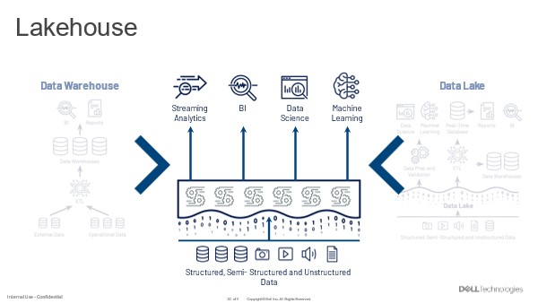
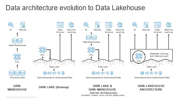
In the What is Data Lakehouse? – Unstructured Data Quick Tips (unstructureddatatips.com), we saw that data lakehouse architecture differs from the monolithic design of classic data warehouse implementations and the more tightly coupled designs of big data-era platforms like Hadoop+Hive or PaaS warehouses like Snowflake.
So, how is data lakehouse architecture different and why?
Adapting Data Warehouse Architecture to Cloud
The classic implementation of data warehouse architecture is based on outdated expectations, especially regarding how the warehouse’s functions and resources are instantiated, connected, and accessed. For example, early implementers of data warehouse architecture expected the warehouse to be physically implemented as an RDBMS and for its components to connect to each other using a low-latency, high-throughput bus. They also expected SQL to be the only way to access and manipulate data in the warehouse.
Another expectation was that the data warehouse would be online and available all the time, and its functions would be tightly coupled to each other. This was a feature of its implementation in an RDBMS, but it made it impractical (and impossible) to scale the warehouse’s resources independently.
None of these expectations are true in the cloud. We are familiar with the cloud as a metaphor for virtualization, which is the use of software to abstract and define various virtual resources, and for the scale-up/scale-down elasticity that is a defining characteristic of the cloud.
However, we may not spend as much time thinking about the cloud as a metaphor for event-driven provisioning of virtualized hardware, and the ability to provision software in response to events.
This on-demand dimension is arguably the most important practical benefit of the cloud’s elasticity and a significant difference between the data lakehouse and the classic data warehouse.
The Data Lakehouse as Cloud-native Data Warehouse
Event-driven design on this scale requires a different set of hardware and software requirements, which cloud-native software engineering concepts, technologies, and methods address. Instead of monolithic applications that run on always-on, always-available, physically implemented hardware resources, cloud-native design allows developers to instantiate discrete software functions as loosely coupled services in response to specific events. These loosely coupled services correspond to the functions of an application, and applications are composed of these loosely coupled services, like the data lakehouse and its layered architecture.
What makes the data lakehouse cloud-native? It is cloud-native when it decomposes most, if not all, of the software functions implemented in data warehouse architecture. These functions include:
-
-
-
- One or more functions that can store, retrieve, and modify data;
- one or more functions that can perform various operations (such as joins) on data;
- one or more functions that expose interfaces for users and jobs to store, retrieve, modify data and specify different types of operations to perform on data;
- one or more functions that manage and enforce data access and integrity safeguards;
- one or more functions that generate or manage technical and business metadata;
- one or more functions that manage and enforce data consistency safeguards when two or more users/jobs try to modify the same data simultaneously or when a new user and job tries to update data currently being accessed by prior users/jobs.
-
-
Using this as a guideline, we can say that a “pure” or “ideal” implementation of data lakehouse architecture would include:
-
-
- The lakehouse service itself, which in addition to SQL query provides metadata management, data federation, and data cataloging capabilities. It also serves as a semantic layer by creating, maintaining, and versioning modeling logic, such as denormalized views applied to data in the lake.
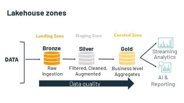
- The data lake, which at minimum provides schema enforcement and the ability to store, retrieve, modify, and schedule operations on objects/blobs in object storage. It also usually provides data profiling and discovery, metadata management, data cataloging, data engineering, and optionally data federation capabilities. It enforces access and data integrity safeguards across its zones and ideally generates and manages technical metadata for the data in these zones.
- An object storage service that provides a scalable, cost-effective storage substrate and handles the work of storing, retrieving, and modifying data stored in file objects.
-
There are different ways to implement the data lakehouse. One option is to combine all these functions into a single omnibus platform, a data lake with its own data lakehouse, like what Databricks, Dremio, and others have done with their data lakehouse implementations.
Why Does Cloud-native Design Matter?
This raises some obvious questions. Why do this? What are the advantages of a loosely coupled architecture compared to the tightly integrated architecture of the classic data warehouse? As mentioned, one benefit of loose coupling is the ability to scale resources independently of each other, such as allocating more compute without adding storage or network resources. It also eliminates some dependencies that can cause software to break, so a change in one service will not necessarily impact or break other services, and the failure of a service will not necessarily cause other services to fail or lose data. Cloud-native design also uses mechanisms like service orchestration to manage and address service failures.
Another benefit of loose coupling is the potential to eliminate dependencies from reliance on a specific vendor’s or provider’s software. If services communicate and exchange data with each other solely through publicly documented APIs, it should be possible to replace a service that provides a set of functions (like SQL query) with an equivalent service. This is the premise of pure or ideal data lakehouse architecture, where each component is effectively commoditized (with equivalent services available from major cloud infrastructure providers, third-party SaaS and/or PaaS providers, and as open-source offerings) and reduces the risk of provider-specific lock-in.
The Data Lakehouse as Event-driven Data Warehouse
Cloud-native software design also expects the provisioning and deprovisioning of the hardware and software resources for loosely coupled cloud-native services to happen automatically. In other words, provisioning a cloud-native service means provisioning its enabling resources, and terminating a cloud-native service means to deprovision these resources. In a way, cloud-native design wants to make hardware and to some extent software disappear as variables in deploying, managing, maintaining, and especially scaling business services.
From the perspective of consumers and expert users, there are only services – tools that do things.
For example, if an ML engineer designs a pipeline to extract and transform data from 100 GBs of log files, a cloud-native compute engine will dynamically provision compute instances to process the workload. Once the engineer’s workload finishes, the engine will automatically terminate these instances.
Ideally, neither the engineer nor the usual IT support people (DBAs, systems and network administrators, so forth) need to do anything to provision these compute instances or the software and hardware resources they depend on. Instead, this all happens automatically – for example, in response to an API call initiated by the engineer. The classic on-premises data warehouse was not designed with this kind of cloud-native, event-driven computing paradigm in mind.
The Data Lakehouse as Its Own Thing
The data lakehouse is supposed to be its own thing, providing the six functions listed above. However, it depends on other services – specifically, an object storage service and optionally a data lake service – to provide basic data storage and core data management functions. In addition, data lakehouse architecture implements novel software functions that have no obvious parallel in classic data warehouse architecture and are unique to the data lakehouse. These functions include:
-
-
- One or more functions that can access, store, retrieve, modify, and perform operations (like joins) on data stored in object storage and/or third-party services. The lakehouse simplifies access to data in Amazon S3, AWS Lake Formation, Amazon Redshift, so forth
- One or more functions that can discover, profile, catalog, and/or facilitate access to distributed data stored in object storage and/or third-party services. For example, a modeler creates denormalized views that combine data stored in the data lakehouse and in the staging zone of an AWS Lake Formation (a data lake), and designs advanced models incorporating data from an Amazon Redshift sales data mart.
-
However, in this respect, the lakehouse is not different from a PaaS data warehouse service, which we will explore in depth in future articles.
 Usually, the data lake is home to all an organization’s useful data. This data is already there. So, the data lakehouse begins with query against this data where it lives.