Unlike previous platforms which used NVDIMMs, the F710 and F210 nodes see a change to the system journal, instead using a 32GB Software Defined Persistent Memory (SDPM) solution to provide persistent storage for the OneFS journal. This change also has the benefit of freeing up a DIMM slot, unlike the NVDIMM on previous platforms.
But before we get into the details, first, a quick refresher on the OneFS journal.
A primary challenge for any storage system is providing performance and ACID (atomicity, consistency, isolation, and durability) guarantees using commodity drives. Drives only support the atomicity of a single sector write, yet complex file system operations frequently update several blocks in a single transaction. For example, a rename operation must modify both the source and target directory blocks. If the system crashes or loses power during an operation that updates multiple blocks, the file system will be inconsistent if some updates are visible and some are not.
The journal is among the most critical components of a PowerScale node. When the OneFS writes to a drive, the data goes straight to the journal, allowing for a fast reply.
OneFS uses journalling to ensure consistency across both disks locally within a node and disks across nodes.
Block writes go to the journal first, and a transaction must be marked as ‘committed’ in the journal before returning success to the file system operation. Once the transaction is committed, the change is guaranteed to be stable. If the node crashes or loses power, the changes can still be applied from the journal at mount time via a ‘replay’ process. The journal uses a battery-backed persistent storage medium, such as NVRAM, in order to be available after a catastrophic node event such as a crash or power loss. It must also be:
| Journal Performance Characteristic | Description |
| High throughput | All blocks (and therefore all data) go through the journal, so it cannot become a bottleneck. |
| Low latency | Since transaction state changes are often in the latency path multiple times for a single operation, particularly for distributed transactions. |
The OneFS journal mostly operates at the physical level, storing changes to physical blocks on the local node. This is necessary because all initiators in OneFS have a physical view of the file system, and therefore issue physical read and write requests to remote nodes. The OneFS journal supports both 512byte and 8KiB block sizes of 512 bytes for storing written inodes and blocks respectively.
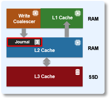
By design, the contents of a node’s journal are only needed in a catastrophe, such as when memory state is lost. For fast access during normal operation, the journal is mirrored in RAM. Thus, any reads come from RAM and the physical journal itself is write-only in normal operation. The journal contents are read at mount time for replay. In addition to providing fast stable writes, the journal also improves performance by serving as a write-back cache for disks. When a transaction is committed, the blocks are not immediately written to disk. Instead, it is delayed until the space is needed. This allows the I/O scheduler to perform write optimizations such as reordering and clustering blocks. This also allows some writes to be elided when another write to the same block occurs quickly, or the write is otherwise unnecessary, such as when the block is freed.
So the OneFS journal provides the initial stable storage for all writes and does not release a block until it is guaranteed to be stable on a drive. This process involves multiple steps and spans both the file system and operating system. The high-level flow is as follows:
| Step | Operation | Description |
| 1 | Transaction prep | A block is written on a transaction, for example a write_block message is received by a node. An asynchronous write is started to the journal. The transaction prepare step will wait until all writes on the transaction complete. |
| 2 | Journal delayed write | The transaction is committed. Now the journal issues a delayed write. This simply marks the buffer as dirty. |
| 3 | Buffer monitoring | A daemon monitors the number of dirty buffers and issues the write to the drive upon reach its threshold. |
| 4 | Write completion notification | The journal receives an upcall indicating that the write is complete. |
| 5 | Threshold reached | Once journal space runs low or an idle timeout expires, the journal issues a cache flush to the drive to ensure the write is stable. |
| 6 | Flush to disk | When cache flush completes, all writes completed before the cache flush are known stable. The journal frees the space. |
The F710 and F210 see the introduction of Dell’s VOSS M.2 SSD drive as the non-volatile device for the SDPM journal vault. The SDPM itself comprises two main elements:
| Component | Description |
| BBU | The BBU pack (battery backup unit) supplies temporary power to the CPUs and memory allowing them to perform a backup in the event of a power loss. |
| Vault | A 32GB M.2 NVMe to which the system memory is vaulted. |
While the BBU is self-contained, the M.2 NVMe vault is housed within a VOSS module, and both components are easily replaced if necessary.
The following CLI command confirms the 32GB size of the SDPM journal in the F710 and F210 nodes:
# grep -r supported_size /etc/psi/psf

/etc/psi/psf/MODEL_F210/journal/JOURNAL_SDPM/journal-1.0-psi.conf:             supported_size = 34359738368;

/etc/psi/psf/MODEL_F710/journal/JOURNAL_SDPM/journal-1.0-psi.conf:             supported_size = 34359738368;

/etc/psi/psf/journal/JOURNAL_NVDIMM_1x16GB/journal-1.0-psi.conf:               supported_size = 17179869184;
The basic SDPM operation is illustrated in the diagram below:
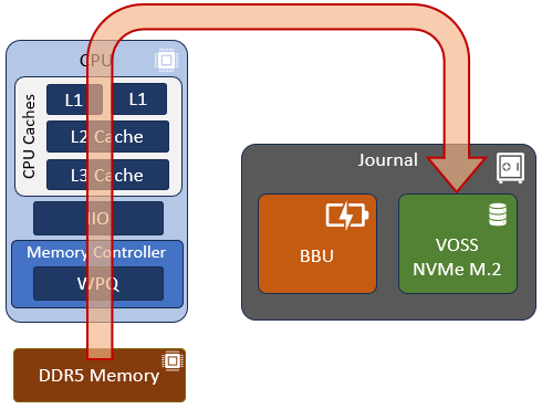
Essentially, the node’s memory state, including any uncommitted writes, etc, in the DDR5 RDIMMS that are being protected, come up through the memory controller, through the CPU and caching hierarchy, and are then vaulted to the non-volatile M.2 within the VOSS module.
The VOSS M.2 module itself is comprised of the following parts:
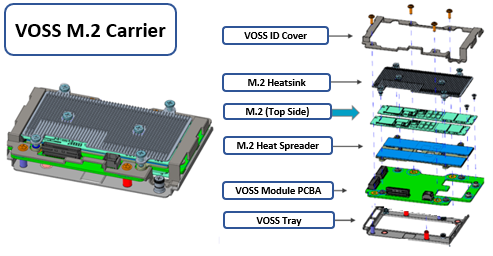
In the event of a failure, this entire carrier assembly is replaced, rather than just the M.2 itself.
Note that with the new VOSS, M.2 firmware upgrades are now managed by iDRAC using DUP, rather than by OneFS and the DSP as in prior PowerScale platforms.
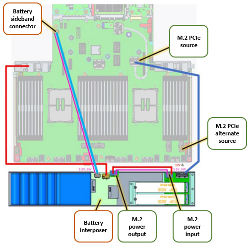
Both the BBU and VOSS module are located at the front of the chassis, and are connected to the motherboard and power source as depicted by the red and blue lines in the following graphic:
Additionally, with OneFS 9.7, given the low latency IO characteristics of the drives, the PowerScale NVMe-based all-flash nodes also now have a write operation fast path direct to SSD for newly allocated blocks as shown below:
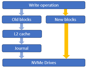
This is a major performance boost, particularly for streaming write workloads, and we’ll explore this more closely in a future article.