OneFS SmartSync Backup-to-Object Configuration

As we saw in the previous article in this series, SmartSync in OneFS 9.11 sees the addition of backup-to-object, which provides high performance, full-fidelity incremental replication to ECS, ObjectScale, Wasabi, and AWS S3 & Glacier IR object stores.

This new SmartSync backup-to-object functionality supports the full spectrum of OneFS path lengths, encodings, and file sizes up to 16TB – plus special files and alternate data streams (ADS), symlinks and hardlinks, sparse regions, and POSIX and SMB attributes. Specifically:

Copy-to-object (OneFS 9.10 & earlier) Backup-to-object (OneFS 9.11)
·         One-time file system copy to object

·         Baseline replication only, no support for incremental copies

·         Browsable/accessible filesystem-on-object representation

·         Certain object limitations

o   No support for sparse regions and hardlinks

o   Limited attribute/metadata support

o   No compression

·         Full-fidelity file system baseline & incremental replication to object

o   Supports ADS, special files, symlinks, hardlinks, sparseness, POSIX/NT attributes, and encoding

o   Any file size and any path length

·         Fast incremental copies

·         Compact file system snapshot representation in native cloud

·         Object representation

o   Grouped by target base-path in policy configuration

o   Further grouped by Dataset ID, Global File ID

SmartSync backup-to-object operates on user-defined data set, which are essentially OneFS file system snapshots with plus additional properties.

A data set creation policy takes snapshots and creates a data set out of it. Additionally, there are also copy and repeat copy policies which are the policies that will transfer that data set to another system. And the execution of these two policy types can be linked and scheduled separately. So you can have one schedule for your data set creation, say to create a data set every hour on a particular path. And you can have a tiered or different distribution system for the actual copy itself. For example, to copy every hour to a hot DR cluster in data center A. But also copy every month to a deep archive cluster in data center B. So all these things are possible now, without increasing the bloat of snapshots on the system, since they’re now able to be shared.

Currently, SmartSync does not have a WebUI presence, so all its configuration is either via the command-line or platform API.

Here’s the procedure for crafting a baseline replication config:

Essentially, create the replication account, which in OneFS 9.11 will be either Dell ECS or Amazon AWS. Then configure that dataset creation policy, run it, and, if desired, create a repeat-copy policy. These specific steps with their CLI syntax include:

  1. Create a replication account:
# isi dm account create --account-type [AWS_S3 | ECS_S3]
  1. Configure a dataset creation policy
# isi dm policies create [Policy Name] --policy-type CREATION
  1. Run the dataset creation policy:
# isi dm policies list

# isi dm policies modify [Creation policy id] –-run-now=true

# isi dm jobs list

# isi dm datasets list
  1. create a repeat-copy policy
# isi dm policies create [Policy Name] --policy-type=' REPEAT_COPY'
  1. Run the repeat-copy policy:
# isi dm policies list

# isi dm policies modify [Repeat-copy policy id] –-run-now=true
  1. View the data replication job status
# isi dm jobs list

Similarly for an incremental replication config:

Note that the dataset creation policy and repeat-copy policy are already created in the baseline replication configure and can be ignored.

Incremental replication using the dataset create and repeat-copy policies from the previous slide’s baseline config.

  1. Run the dataset creation policy
# isi dm policies list

# isi dm policies modify [Creation policy id] –-run-now=true

# isi dm jobs list

# isi dm datasets list
  1. Run the repeat-copy policy:
# isi dm policies list

# isi dm policies modify [Repeat-copy policy id] –-run-now=true
  1. View the data replication incremental job status
# isi dm jobs list

And here’s the basic procedure for creating and running a partial or full restore:

Note that the replication account is already created on the original cluster and the creation step can be ignored.  Replication account creation is only required if restoring the dataset to a new cluster.

Additionally, partial restoration involves a subset of the directory structure, specified via the ‘source path’ , whereas full restoration invokes a restore of the entire dataset.

The process includes creating the replication account if needed, finding the ID of the dataset to be restored, creating and running the partial or full restoration policy, and checking the job status to verify it ran successfully.

  1. Create a replication account:
# isi dm account create --account-type [AWS_S3 | ECS_S3]

For example:

# isi dm account create --account-type ECS_S3 --name [Account Name] --access-id [access-id] --uri [URI with bucket-name] --auth-mode CLOUD --secret-key [secret-key] --storage-class=[For AWS_S3 only: STANDARD or GLACIER_IR]
  1. Verify the dataset ID for restoration:
# isi_dm browse

Checking the following attributes:

  • list-accounts
  • connect-account [Source Account ID created in step 1]
  • list-datasets
  • connect-dataset [Dataset id]
  1. Create a partial or full restoration policy
# isi dm policies create [Policy Name] --policy-type='COPY'
  1. Run the partial or full restoration policy:
# isi dm policies modify [Restoration policy id] –-run-now=true
  1. View the data restoration job status
# isi dm jobs list

OneFS 9.11 also introduces recovery point objective or RPO alerts for SmartSync, but note that these are for repeat-copy policies only. These RPO alerts can be configured through the replication policy by adding the desired time value to the ‘repeat-copy-rpo-alert’ parameter. If this configured threshold is exceeded, an RPO alert is triggered. This RPO alert is automatically resolved after the next successful policy job run.

Also be aware that the default time value for a repeat copy RPO is zero, which instructs SmartSync to not generate RPO alerts for that policy.

The following CLI syntax can be used to create a replication policy, with the ‘–repeat-copy-rpo-alert’ flag set for the desired time:

# isi dm policies create [Policy Name] --policy-type=' REPEAT_COPY' --enabled='true' --priority='NORMAL' --repeat-copy-source-base-path=[Source Path] --repeat-copy-base-base-account-id=[Source account id] --repeat-copy-base-source-account-id=[Source account id] --repeat-copy-base-target-account-id=[Target account id] --repeat-copy-base-new-tasks-account=[Source account id] --repeat-copy-base-target-dataset-type='FILE_ON_OBJECT_BACKUP' --repeat-copy-base-target-base-path=[Bucket Name] --repeat-copy-rpo-alert=[time]

And similarly to change the RPO alert configuration on an existing replication policy:

# isi dm policies modify [Policy id] --repeat-copy-rpo-alert=[time]

An alert is triggered and corresponding CELOG event created if the specified RPO for the policy is exceeded. For example:

# isi event list

ID   Started     Ended       Causes Short                     Lnn  Events  Severity

--------------------------------------------------------------------------------------

1898 07/15 00:00 07/15 00:00 SW_CELOG_HEARTBEAT               1    1       information

2012 07/15 06:03 --          SW_DM_RPO_EXCEEDED               2    1       warning

--------------------------------------------------------------------------------------

And then once RPO alert has been resolved after a successful replication policy job run:

# isi event list

ID   Started     Ended       Causes Short                     Lnn  Events  Severity

--------------------------------------------------------------------------------------

1898 07/15 00:00 07/15 00:00 SW_CELOG_HEARTBEAT               1    1       information

2012 07/15 06:03 07/15 06:12 SW_DM_RPO_EXCEEDED               2    2       warning

--------------------------------------------------------------------------------------

OneFS SmartSync Backup-to-Object

Another significant benefactor of new functionality in the recent OneFS 9.11 release is SmartSync. As you may recall, SmartSync allows multiple copies of a dataset to be copied, replicated, and stored across locations and regions, both on and off-prem, providing increased data resilience and the ability to rapidly recover from catastrophic events.

In addition to fast, efficient, scalable protection with granular recovery, SmartSync allows organizations to utilize lower cost object storage as the target for backups, reduce data protection complexity and cost by eliminating the need for separate backup applications. Plus disaster recovery options include restoring a dataset to its original state, or cloning a new cluster.

SmartSync sees the following enhancements in OneFS 9.11:

  • Automated incremental-forever replication to object storage.
  • Unparalleled scalability and speed, with seamless pause/resume for robust resiliency and control.
  • End-to-end encryption for security of data-in-flight and at rest.
  • Complete data replication, including soft/hard links, full file paths, and sparse files
  • Object storage targets: AWS S3, AWS Glacier IR, Dell ECS/ObjectScale, and Wasabi (with the addition of Azure and GCP support in a future release).

But first, a bit of background. Introduced back in OneFS 9.4, SmartSync operates in two distinct modes:

  • Regular push-and-pull transfer of file data between PowerScale clusters.
  • CloudCopy, copying of file-to-object data from a source cluster to a cloud object storage target.

CloudCopy copy-to-object in OneFS 9.10 and earlier releases is strictly a one-time copy tool, rather than a replication utility. So, after a copy, viewing the bucket contents from AWS, console or S3 browser yielded an object format tree-like representation of the OneFS file system. However, there were a number of significant shortcomings, such as no native support for attributes like ACLs, or certain file types like character files, and no method to represent hard links in a reasonable way. So OneFS had to work around these things by expanding hard links, and redirecting objects that had too long of a path. The other major limitation was that it really had just been a one-and-done copy. After creating and running a policy, once the job had completed the data was in the cloud, and that was it. OneFS had no provision for any incremental transfer of any subsequent changes to the cloud copy when the source data changed.

In order to address these limitations, SmartSync in OneFS 9.11 sees the addition of backup-to-object functionality. This includes a full-fidelity file system baseline, plus fast incremental replication to Dell ECS and ObjectScale, Wasabi, and AWS S3 and Glacier IR object stores.

This new backup-to-object functionality supports the full range of OneFS path lengths, encodings, and file sizes up to 16TB – plus special files and alternate data streams (ADS), symlinks and hardlinks, sparse regions, and POSIX and SMB attributes.

Copy-to-object (OneFS 9.10 & earlier) Backup-to-object (OneFS 9.11)
·         One-time file system copy to object

·         Baseline replication only, no support for incremental copies

·         Browsable/accessible filesystem-on-object representation

·         Certain object limitations

o   No support for spareness and hardlinks

o   Limited attribute/metadata support

o   No compression

·         Full-fidelity file system baseline & incremental replication to object

o   Supports ADS, special files, symlinks, hardlinks, sparseness, POSIX/NT attributes, and encoding

o   Any file size and any path length

·         Fast incremental copies

·         Compact file system snapshot representation in native cloud

·         Object representation

o   Grouped by target basepath in policy configuration

o   Further grouped by Dataset ID, Global File ID


Architecturally, SmartSync incorporates the following concepts:

Concept Description
Account •      References to systems that participate in jobs (PowerScale clusters, cloud hosts)

•      Made up of a name, a URI and auth info

Dataset •      Abstraction of a filesystem snapshot; the thing we copy between systems

•      Identified by Dataset IDs

Global File ID •      Conceptually a global LIN that references a specific file on a specific system
Policy •      Dataset creation policy creates a dataset

•      Copy/Repeat Copy policies take an existing dataset and put it on another system

•      Policy execution can be linked and scheduled


Push/Pull, Cascade/Reconnect


•      Clusters syncing to each other in sequence (A>B>C)

•      Clusters can skip baseline copy and directly perform incremental updates (A>C)

•      Clusters can both request and send datasets

Transfer resiliency


•      Small errors don’t need to halt a policy’s progress

Under the hood, SmartSync uses this concept of a data set, which is fundamentally an abstraction of a OneFS file system snapshot – albeit with some additional properties attached to it.

Each data set is identified by a unique ID. Plus, with this notion of data sets, OneFS can now also perform an A to B replication and an A to C replication – two replications of the same data set to two different targets. Plus with these new data sets, B and C can now also reference each other and perform incremental replication amongst themselves, assuming they have a common ancestor snapshot that they share.

A SmartSync data set creation policy takes snapshots and creates a data set from it. Additionally, there are also copy and repeat copy policies, which are the policies that are used to transfer that data set to another system. The execution of these two policy types can be linked and scheduled separately. So one schedule can be for data set creation, say to create a data set every hour on a particular path, and the other schedule for a tiered or different distribution system for the actual copy itself. For example, in order to copy hourly to a hot DR cluster in data center A, and also copy monthly to a deep archive cluster in data center B – all without increasing the proliferation of snapshots on the system, since they’re now able to be shared.

Additionally, SmartSync in 9.11 also introduces the foundational concept of a global file ID (GFID), which is essentially a global LIN that represents a specific file on a particular system. OneFS can now use this GFID, in combination with a data set, to reference a file anywhere and guarantee that it means the same thing across every cluster.

Security-wise, each SmartSync daemon has an identity certificate that acts as both a client and server certificate depending on the direction of the data movement. This identity certificate is signed by a non-public certificate authority. To establish trust between two clusters, they must have each other’s CAs. These CAs may be the same. Trust groups (daemons that may establish connections to each other) are formed by having shared CAs installed.

There are no usernames or passwords; authentication is authorization for V1. All cluster-to-cluster communication is performed via TLS-encrypted traffic. If absolutely necessary, encryption (but not authorization) can be disabled by setting a ‘NULL’ encryption cipher for specific use cases that require unencrypted traffic.

The SmartSync daemon supports checking certificate revocation status via the Online Certificate Status Protocol (OCSP). If the cluster is hardened and/or in FIPS-compliant mode, OCSP checking is forcibly enabled and set to the Strict stringency level, where any failure in OCSP processing results in a failed TLS handshake. Otherwise, OCSP checking can be totally disabled or set to a variety of values corresponding to desired behavior in cases where the responder is unavailable, the responder does not have information about the cert in question, and where information about the responder is missing entirely. Similarly, an override OCSP responder URI is configurable to support cases where preexisting certificates do not contain responder information.

SmartSync also supports a ‘strict hostname check’ option which mandates that the common name and/or subject alternative name fields of the peer certificate match the URI used to connect to that peer. This option, along with strict OCSP checking and disabling the null cipher option, are forcibly set when the cluster is operating in a hardened or FIPS-compliant mode.

For object storage connections, SmartSync uses ‘isi_cloud_api’ just as CloudPools does. As such, all considerations that apply to CloudPools also apply to SmartSync as well.

In the next article in this series, we’ll turn our attention to the core architecture and configuration of SmartSync backup-to-object.

PowerScale H and A-series Journal Mirroring and Hardware Resilience

The last couple of articles generated several questions for the field around durability and resilience in the newly released PowerScale H710/0 and A310/0 nodes. In this article, we’ll take a deeper look at the OneFS journal and boot drive mirroring functionality in these H and A-series platforms.

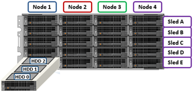
PowerScale chassis-based hardware, such as the new H710/7100 and A310/3100, stores the local filesystem journal and its mirror on persistent, battery-backed flash media within each node, with a 4RU PowerScale chassis housing four nodes. These nodes comprise a ‘compute node enclosure for the CPU, memory, and, and network cards, plus associated drive containers, or sleds, for each node.

The PowerScale H and A-series employ a node-pair architecture to dramatically increased system reliability, with each pair of nodes residing within a chassis power zone. This means that if a node’s PSU fails, the peer PSU supplies redundant power. It also drives a minimum cluster or node pool size of four nodes (one chassis) for the PowerScale H and A-series platforms, pairwise node population, and the need to scale the cluster two nodes at a time.

A node’s file system journal is protected against sudden power loss or hardware failure by OneFS’ journal vault functionality – otherwise known as ‘powerfail memory persistence’, or PMP. PMP automatically stores both the local journal and journal mirror on a separate flash drive across both nodes in a node pair:

This journal de-staging process is known as ‘vaulting’, during which the journal is protected by a dedicated battery in each node until it’s safely written from DRAM to SSD on both nodes in a node-pair. With PMP, constant power isn’t required to protect the journal in a degraded state since the journal is saved to M.2 flash and mirrored on the partner node.

So, the mirrored journal is comprised of both hardware and software components, including the following constituent parts:

Journal Hardware Components

  • System DRAM
  • 2 Vault Flash
  • Battery Backup Unit (BBU)
  • Non-Transparent Bridge (NTB) PCIe link to partner node
  • Clean copy on disk

Journal Software Components

  • Power-fail Memory Persistence (PMP)
  • Mirrored Non-volatile Interface (MNVI)
  • IFS Journal + Node State Block (NSB)
  • Utilities

Asynchronous DRAM Refresh (ADR) preserves RAM contents when the operating system is not running. ADR is important for preserving RAM journal contents across reboots, and it does not require any software coordination to do so.

The journal vaulting functionality encompasses the hardware, firmware, and operating system, ensuring that the journal’s contents are preserved across power failure. The mechanism is similar to the software journal mirroring employed on the PowerScale F-series nodes, albeit using a PCIe-based NTB on the chassis based platforms, instead of using the back-end network as with the all-flash nodes.

On power failure, the PMP vaulting functionality is responsible for copying both the local journal and the local copy of the partner node’s journal to persistent flash. On restoration of power, PMP is responsible for restoring the contents of both journals from flash to RAM, and notifying the operating system.

A single dedicated 480GB NVMe flash device (nvd0) is attached via an M.2 slot on the motherboard of the H710/0 and A310/0 node’s compute module, residing under the battery backup unit (BBU) pack.

This is in contrast to the prior H and A-series chassis generations, which used a 128GB SATA M.2 device (/dev/ada0).

For example, the following CLI commands show the NVMe M.2 flash device in an A310 node:

# isi_hw_status | grep -i prod
Product: A310-4U-Single-96GB-1x1GE-2x25GE SFP+-60TB-1638GB SSD-SED

# nvmecontrol devlist
 nvme0: Dell DN NVMe FIPS 7400 RI M.2 80 480GB
    nvme0ns1 (447GB)

# gpart show | grep nvd0
=>       40  937703008  nvd0  GPT  (447G)

# gpart show -l nvd0
=>       40  937703008  nvd0  GPT  (447G)
         40       2008        - free -  (1.0M)
       2048   41943040     1  isilon-pmp  (20G)
   41945088  895757960        - free -  (427G)

In the above, the ‘isilon-pmp’ partition on the M.2 flash device is used by the file system journal for its vaulting activities.

The the NVMe M.2 device is housed on the node compute module’s riser card, and its firmware is managed by the OneFS DSP (drive support package) framework:

Note that the entire compute module must be removed in order for its M.2 flash to be serviced. If the M.2 flash does need to be replaced for any reason, it will be properly partitioned and the PMP structure will be created as part of arming the node for vaulting.

For clusters using data-at-rest encryption (DARE), an encrypted M.2 device is used, in conjunction with SED data drives, to provide full FIPS compliance.

The battery backup unit (BBU), when fully charged, provides enough power to vault both the local and partner journal during a power failure event:

A single battery is utilized in the BBU, which also supports back-to-back vaulting:

On the software side, the journal’s Power-fail Memory Persistence (PMP) provides an equivalent to the NVRAM controller‘s vault/restore capabilities to preserve Journal. The PMP partition on the M.2 flash drive provides an interface between the OS and firmware.

If a node boots and its primary journal is found to be invalid for whatever reason, it has three paths for recourse:

  • Recover journal from its M.2 vault.
  • Recover journal from its disk backup copy.
  • Recover journal from its partner node’s mirrored copy.

The mirrored journal must guard against rolling back to a stale copy of the journal on reboot. This necessitates storing information about the state of journal copies outside the journal. As such, the Node State Block (NSB) is a persistent disk block that stores local and remote journal status (clean/dirty, valid/invalid, etc), as well as other non-journal information. NSB stores this node status outside the journal itself, and ensures that a node does not revert to a stale copy of the journal upon reboot.

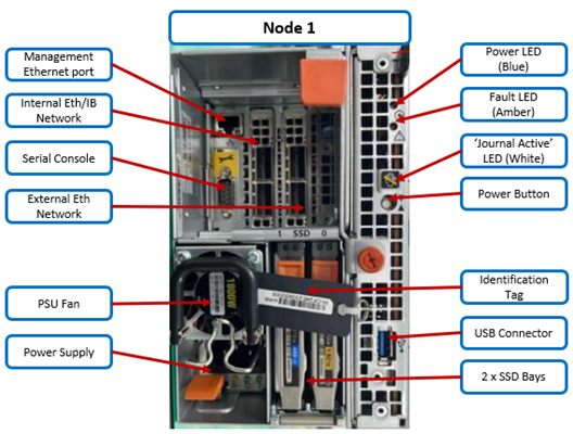
Here’s the detail of an individual node’s compute module:

Of particular note is the ‘journal active’ LED, which is displayed as a white ‘hand icon’:

When this white hand icon is illuminated, it indicates that the mirrored journal is actively vaulting, and it is not safe to remove the node!

There is also a blue ‘power’ LED, and a yellow ‘fault’ LED per node. If the blue LED is off, the node may still be in standby mode, in which case it may still be possible to pull debug information from the baseboard management controller (BMC).

The flashing yellow ‘fault’ LED has several state indication frequencies:

Blink Speed Blink Frequency Indicator
Fast blink ¼ Hz BIOS
Medium blink 1 Hz Extended POST
Slow blink 4 Hz Booting OS
Off Off OS running

The mirrored non-volatile interface (MNVI) sits below /ifs and above RAM and the NTB, providing the abstraction of a reliable memory device to the /ifs journal. MNVI is responsible for synchronizing journal contents to peer node RAM, at the direction of the journal, and persisting writes to both systems while in a paired state. It upcalls into the journal on NTB link events, and notifies the journal of operation completion (mirror sync, block IO, etc). For example, when rebooting after a power outage, a node automatically loads the MNVI. It then establishes a link with its partner node and synchronizes its journal mirror across the PCIe Non-Transparent Bridge (NTB).

The Non-transparent Bridge (NTB) connects node pairs for OneFS Journal Replica:

The NTB Link itself is PCIe Gen3 X8, but there is no guarantee of NTB interoperability between different CPU generations. As such, the H710/0 and A310/0 use version 4 of the NTB driver, whereas the previous hardware generation uses NTBv3. This therefore means mixed-generation node pairs are unsupported.

Prior to mounting the /ifs file system, OneFS locates a valid copy of the journal from one of the following locations in order of preference:

Order Journal Location Description
1st Local disk A local copy that has been backed up to disk
2nd Local vault A local copy of the journal restored from Vault into DRAM
3rd Partner node A mirror copy of the journal from the partner node

Assuming the node was shut down cleanly, it will boot using a local disk copy of the journal. The journal will be restored into DRAM and /ifs will mount. On the other hand, if the node suffered a power disruption, the journal will be restored into DRAM from the M.2 vault flash instead (the PMP copies the journal into the M.2 vault during a power failure).

In the event that OneFS is unable to locate a valid journal on either the hard drives or M.2 flash on a node, it will retrieve a mirrored copy of the journal from its partner node over the NTB.  This is referred to as ‘Sync-back’.

Note: Sync-back state only occurs when attempting to mount /ifs.

On booting, if a node detects that its journal mirror on the partner node is out of sync (invalid), but the local journal is clean, /ifs will continue to mount.  Subsequent writes are then copied to the remote journal in a process known as ‘sync-forward’.

Here’s a list of the primary journal states:

Journal State Description
Sync-forward State in which writes to a journal are mirrored to the partner node.
Sync-back Journal is copied back from the partner node. Only occurs when attempting to mount /ifs.
Vaulting Storing a copy of the journal on M.2 flash during power failure. Vaulting is performed by PMP.

During normal operation, writes to the primary journal and its mirror are managed by the MNVI device module, which writes through local memory to the partner node’s journal via the NTB. If the NTB is unavailable for an extended period, write operations can still be completed successfully on each node. For example, if the NTB link goes down in the middle of a write operation, the local journal write operation will complete. Read operations are processed from local memory.

Additional journal protection for PowerScale chassis-based platforms is provided by OneFS’ powerfail memory persistence (PMP) functionality, which guards against PCI bus errors that can cause the NTB to fail.  If an error is detected, the CPU requests a ‘persistent reset’, during which the memory state is protected and node rebooted. When back up again, the journal is marked as intact and no further repair action is needed.

If a node loses power, the hardware notifies the BMC, initiating a memory persistent shutdown.  At this point the node is running on battery power. The node is forced to reboot and load the PMP module, which preserves its local journal and its partner’s mirrored journal by storing them on M.2 flash.  The PMP module then disables the battery and powers itself off.

Once power is back on and the node restarted, the PMP module first restores the journal before attempting to mount /ifs.  Once done, the node then continues through system boot, validating the journal, setting sync-forward or sync-back states, etc.

The mirrored journal has the following CLI commands, although these should seldom be needed during normal cluster operation:

  • isi_save_journal
  • isi_checkjournal
  • isi_testjournal
  • isi_pmp

A node’s journal can be checked and confirmed healthy as follows:

# isi_testjournal
Checking One external batteries Health...
Batteries good
Checking PowerScale Journal integrity...
Mounted DRAM journal check: good
IFS is mounted.

During boot, isi_checkjournal and isi_testjournal will invoke isi_pmp. If the M.2 vault devices are unformatted, isi_pmp will format the devices.

On clean shutdown, isi_save_journal stashes a backup copy of the /dev/mnv0 device on the root filesystem, just as it does for the NVRAM journals in previous generations of hardware.

If a mirrored journal issue is suspected, or notified via cluster alerts, the best place to start troubleshooting is to take a look at the node’s log events. The journal logs to /var/log/messages, with entries tagged as ‘journal_mirror’.

Additionally, the following sysctls also provide information about the state of the journal mirror itself and the MNVI connection respectively:

# sysctl efs.journal.mirror_state
efs.journal.mirror_state:
{
    Journal state: valid_protected
    Journal Read-only: false
    Need to inval mirror: false
    Sync in progress: false
    Sync error: 0
    Sync noop in progress: false
    Mirror work queued: false
    Local state:
    {
        Clean: dirty
        Valid: valid
    }
    Mirror state:
    {
        Connection: up
        Validity: valid
    }
}

And the MNVI connection state:

# sysctl hw.mnv0.state
hw.mnv0.state.iocnt: 0
hw.mnv0.state.cb_active: 0
hw.mnv0.state.io_gate: 0
hw.mnv0.state.state: 3

OneFS provides the following CELOG events for monitoring and alerting about mirrored journal issues:

CELOG Event Description
HW_GEN6_NTB_LINK_OUTAGE Non-transparent bridge (NTP) PCIe link is unavailable
FILESYS_JOURNAL_VERIFY_FAILURE No valid journal copy found on node

Another OneFS reliability optimization for the PowerScale chassis-based platforms is boot partition mirroring. OneFS boot and other OS partitions are stored on a node’s internal drives, and these partitions are mirrored (with the exception of crash dump partitions). The two mirrors protect against disk sled removal. Since each drive in a disk sled belongs to a separate disk pool, both elements of a mirror cannot live on the same sled.

With regard to the nodes’ internal drives, the boot disk reservation size has increased to 18GB on these new platforms from 8GB on the previous generation. Plus partition sizes have also been expanded on these new platforms in OneFS 9.11, as follows:

Partition H71x and A31x H70x and A30x
hw 1GB 500MB
journal backup 8197MB 8GB
kerneldump 5GB 2GB
keystore 64MB 64MB
root 4GB 2GB
var 4GB 2GB
var-crash 7GB 3GB

OneFS automatically rebalances these mirrors in anticipation of, and in response to, service events. Mirror rebalancing is triggered by drive events such as suspend, softfail and hard loss.

The ‘isi_mirrorctl verify’ and ‘gmirror status’ CLI commands can be used to confirm that boot mirroring is working as intended. For example, on an A310 node:

# gmirror status
Name Status Components
mirror/root0 COMPLETE da10p3 (ACTIVE)
da11p3 (ACTIVE)
mirror/mfg COMPLETE da15p7 (ACTIVE)
da12p6 (ACTIVE)
mirror/kernelsdump COMPLETE da15p6 (ACTIVE)
mirror/kerneldump COMPLETE da15p5 (ACTIVE)
mirror/var-crash COMPLETE da15p3 (ACTIVE)
da9p3 (ACTIVE)
mirror/journal-backup COMPLETE da14p5 (ACTIVE)
da12p5 (ACTIVE)
mirror/jbackup-peer COMPLETE da14p3 (ACTIVE)
da12p3 (ACTIVE)
mirror/keystore COMPLETE da12p7 (ACTIVE)
da10p10 (ACTIVE)
mirror/root1 COMPLETE da11p7 (ACTIVE)
da10p7 (ACTIVE)
mirror/var0 COMPLETE da11p6 (ACTIVE)
da10p6 (ACTIVE)
mirror/hw COMPLETE da10p9 (ACTIVE)
da7p5 (ACTIVE)
mirror/var1 COMPLETE da10p8 (ACTIVE)
da7p3 (ACTIVE)

Or:

# isi_mirrorctl verify
isi.sys.distmirror - INFO - Mirror root1: has an ACTIVE consumer of da11p5
isi.sys.distmirror - INFO - Mirror root1: has an ACTIVE consumer of da10p7
isi.sys.distmirror - INFO - Mirror var1: has an ACTIVE consumer of da13p5
isi.sys.distmirror - INFO - Mirror var1: has an ACTIVE consumer of da16p5
isi.sys.distmirror - INFO - Mirror journal-backup: has an ACTIVE consumer of da12p5
isi.sys.distmirror - INFO - Mirror journal-backup: has an ACTIVE consumer of da16p6
isi.sys.distmirror - INFO - Mirror jbackup-peer: has an ACTIVE consumer of da12p3
isi.sys.distmirror - INFO - Mirror jbackup-peer: has an ACTIVE consumer of da14p3
isi.sys.distmirror - INFO - Mirror var-crash: has an ACTIVE consumer of da10p6
isi.sys.distmirror - INFO - Mirror var-crash: has an ACTIVE consumer of da11p3
isi.sys.distmirror - INFO - Mirror kerneldump: has an ACTIVE consumer of da14p5
isi.sys.distmirror - INFO - Mirror root0: has an ACTIVE consumer of da10p3
isi.sys.distmirror - INFO - Mirror root0: has an ACTIVE consumer of da13p6
isi.sys.distmirror - INFO - Mirror var0: has an ACTIVE consumer of da13p3
isi.sys.distmirror - INFO - Mirror var0: has an ACTIVE consumer of da16p3
isi.sys.distmirror - INFO - Mirror kernelsdump: has an ACTIVE consumer of da14p6
isi.sys.distmirror - INFO - Mirror mfg: has an ACTIVE consumer of da13p9
isi.sys.distmirror - INFO - Mirror mfg: has an ACTIVE consumer of da16p7
isi.sys.distmirror - INFO - Mirror hw: has an ACTIVE consumer of da10p8
isi.sys.distmirror - INFO - Mirror hw: has an ACTIVE consumer of da13p8
isi.sys.distmirror - INFO - Mirror keystore: has an ACTIVE consumer of da13p10
isi.sys.distmirror - INFO - Mirror keystore: has an ACTIVE consumer of da16p8

The A310 node’s disks in the output above are laid out as follows:

# isi devices drive list
Lnn  Location  Device    Lnum  State   Serial       Sled
---------------------------------------------------------
128  Bay  1    /dev/da1  15    L3      X3X0A0JFTMSJ N/A
128  Bay  2    -         N/A   EMPTY                N/A
128  Bay  A0   /dev/da4  12    HEALTHY WQB0QKBR     A
128  Bay  A1   /dev/da3  13    HEALTHY WQB0QHV4     A
128  Bay  A2   /dev/da2  14    HEALTHY WQB0QHN3     A
128  Bay  B0   /dev/da7  9     HEALTHY WQB0QH4S     B
128  Bay  B1   /dev/da6  10    HEALTHY WQB0QGY3     B
128  Bay  B2   /dev/da5  11    HEALTHY WQB0QJWE     B
128  Bay  C0   /dev/da10 6     HEALTHY WQB0QJ26     C
128  Bay  C1   /dev/da9  7     HEALTHY WQB0QHYW     C
128  Bay  C2   /dev/da8  8     HEALTHY WQB0QK6Q     C
128  Bay  D0   /dev/da13 3     HEALTHY WQB0QJES     D
128  Bay  D1   /dev/da12 4     HEALTHY WQB0QHGG     D
128  Bay  D2   /dev/da11 5     HEALTHY WQB0QKH5     D
128  Bay  E0   /dev/da16 0     HEALTHY WQB0QHFR     E
128  Bay  E1   /dev/da15 1     HEALTHY WQB0QJWD     E
128  Bay  E2   /dev/da14 2     HEALTHY WQB0QKGB     E
---------------------------------------------------------

When it comes to SmartFailing nodes, there are a couple of additional caveats to be aware of with mirrored journal and the PowerScale chassis-based platforms:

  • When SmartFailing one node in a pair, there is no compulsion to smartfail its partner node too.
  • A node will still run indefinitely with its partner absent. However, this significantly increases the window of risk since there is no journal mirror to rely on (in addition to lack of redundant power supply, etc).
  • If a single node in a pair is SmartFailed, the other node’s journal is still protected by the vault and powerfail memory persistence.

PowerScale A310 and A3100 Platforms

In this article, we’ll examine the new PowerScale A310 and A3100 hardware platforms that were released a couple of weeks back.

These A310 and A3100 comprise the latest generation of PowerScale A-series ‘archive’ platforms:

The PowerScale A-series systems are designed for cooler, infrequently accessed data use cases. These include active archive workflows for the A310, such as regulatory compliance data, medical imaging archives, financial records, and legal documents. And deep archive/cold storage for the A3100 platform, including surveillance video archives, backup, and DR repositories.

Representing the archive-tier, the A310 and A3100 both utilize a single-socket Zeon processor with 96GB of memory and fifteen (A310) or twenty hard drives per node respectively, plus SSDs for metadata/caching – and with four nodes residing within a 4RU chassis. From an initial 4 node (1 chassis) starting point, A310 and A31100 clusters can be easily and non-disruptively scaled two nodes at a time up to a maximum of 252 nodes (63 chassis) per cluster.

The A31x modular platform is based on Dell’s ‘Infinity’ chassis. Each node’s compute module contains a single 16-core Intel Sapphire Rapids CPU running at 1.8 GHz and with 22.5MB of cache, plus 96GB of DDR5 DRAM. Front-End networking options include 10/25 GbE and with both Ethernet or Infiniband as selectable options for the back-End network.

As such, the new A31x core hardware specifications are as follows:

Hardware Class PowerScale A-Series (Archive)
Model A310 A3100
OS version Requires OneFS 9.11 or above.

Requires NFP 13.1 or greater.

BIOS based on Dell’s PowerBIOS

Requires OneFS 9.11 or above.

Requires NFP 13.1 or greater.

BIOS based on Dell’s PowerBIOS

Platform Four nodes per 4RU chassis; upgradeable per pair; node-compatible with prior gens. Four nodes per 4RU chassis; upgradeable per pair; node-compatible with prior gens.
CPU 8 Cores @ 1.8GHz, 22.5MB Cache 8 Cores @ 1.8GHz, 22.5MB Cache
Memory 96GB DDR5 DRAM 96GB DDR5 DRAM
Journal M.2: 480GB NVMe with 3-cell battery backup (BBU) M.2: 480GB NVMe with 3-cell battery backup (BBU)
Depth Standard 36.7 inch chassis Deep 42.2 inch chassis
Cluster size Max of 63 chassis (252 nodes) per cluster. Max of 63 chassis (252 nodes) per cluster.
Storage Drives 60 per chassis     (15 per node) 80 per chassis     (20 per node)
HDD capacities 2TB,4TB, 8TB, 12TBTB, 16TB, 20TB, 24TB 12TBTB, 16TB, 20TB, 24TB
SSD (cache) capacities 0.8TB, 1.6TB, 3.2TB, 7.68TB 0.8TB, 1.6TB, 3.2TB, 7.68TB
Max raw capacity 1.4PB per chassis 1.9PB per chassis
Front-end network 10/25 Gb Ethernet 10/25 Gb Ethernet
Back-end network Ethernet or Infiniband Ethernet or Infiniband

These node hardware attributes can be easily viewed from the OneFS CLI via the ‘isi_hw_status’ command. For example, from an A3100:

# isi_hw_status
  SerNo: CF2BC243400025

 Config: H6R28

ChsSerN:

ChsSlot: 1

FamCode: A

ChsCode: 4U

GenCode: 10

PrfCode: 3

   Tier: 3
  Class: storage
 Series: n/a
Product: A3100-4U-Single-96GB-1x1GE-2x25GE SFP+-240TB-6554GB SSD
  HWGen: PSI

Chassis: INFINITY (Infinity Chassis)

    CPU: GenuineIntel (1.80GHz, stepping 0x000806f8)

   PROC: Single-proc, Octa-core

    RAM: 103079215104 Bytes

   Mobo: INFINITYPIFANO (Custom EMC Motherboard)

  NVRam: INFINITY (Infinity Memory Journal) (4096MB card) (size 4294967296B)

 DskCtl: LSI3808 (LSI 3808 SAS Controller) (8 ports)

 DskExp: LSISAS35X36I (LSI SAS35x36 SAS Expander - Infinity)

PwrSupl: Slot1-PS0 (type=ACBEL POLYTECH, fw=03.01)

PwrSupl: Slot2-PS1 (type=ACBEL POLYTECH, fw=03.01)

  NetIF: bge0,lagg0,mce0,mce1,mce2,mce3

 BEType: 25GigE

 FEType: 25GigE

 LCDver: IsiVFD2 (Isilon VFD V2)

 Midpln: NONE (No Midplane Support)

Power Supplies OK

Power Supply Slot1-PS0 good

Power Supply Slot2-PS1 good

CPU Operation (raw 0x882C0800)  = Normal

CPU Speed Limit                 = 100.00%

Fan0_Speed                      = 12360.000

Fan1_Speed                      = 12000.000

Slot1-PS0_In_Voltage            = 212.000

Slot2-PS1_In_Voltage            = 209.000

SP_CMD_Vin                      = 12.100

CMOS_Voltage                    = 3.120

Slot1-PS0_Input_Power           = 290.000

Slot2-PS1_Input_Power           = 290.000

Pwr_Consumption                 = 590.000

SLIC0_Temp                      = na

SLIC1_Temp                      = na

DIMM_Bank0                      = 42.000

DIMM_Bank1                      = 40.000

CPU0_Temp                       = -43.000

SP_Temp0                        = 40.000

MP_Temp0                        = na

MP_Temp1                        = 29.000

Embed_IO_Temp0                  = 51.000

Hottest_SAS_Drv                 = -45.000

Ambient_Temp                    = 29.000

Slot1-PS0_Temp0                 = 47.000

Slot1-PS0_Temp1                 = 40.000

Slot2-PS1_Temp0                 = 47.000

Slot2-PS1_Temp1                 = 40.000

Battery0_Temp                   = 38.000

Drive_IO0_Temp                  = 43.000

Also note that the A310 and A3100 are only available in a 96GB memory configuration.

On the front of each chassis is an LCD front panel control with back-lit buttons and 4 LED Light Bar Segments – 1 per Node. These LEDs typically display blue for normal operation or yellow to indicate a node fault. This LCD display is articulating,  allowing it to be swung clear of the drive sleds for non-disruptive HDD replacement, etc.

The rear of the chassis houses the compute modules for each node, which contain CPU, memory, networking, cache SSDs, and power supplies. Specifically, an individual compute module contains a multi core Cascade Lake CPU, memory, M2 flash journal, up to two SSDs for L3 cache, six DIMM channels, front end 10/25 Gb ethernet, backend 40/100 or 10/25 Gb ethernet or Infiniband, an ethernet management interface, and power supply and cooling fans:

As shown above, the field replaceable components are indicated via colored ‘touchpoints’. Two touchpoint colors, orange and blue, indicate respectively which components are hot swappable versus replaceable via a node shutdown.

Touchpoint Detail
Blue Cold (offline) field serviceable component
Orange Hot (Online) field serviceable component

The serviceable components within an PowerScale A310 or A3100 chassis are as follows:

Component Hot Swap CRU FRU
Drive sled Yes Yes Yes
·         Hard drives (HDDs) Yes Yes Yes
Compute node No Yes Yes
·         Compute module No No No
o   M.2 journal flash No No Yes
o   CPU complex No No No
o   DIMMs No No Yes
o   Node fans No No Yes
o   NICs/HBAs No No Yes
o   HBA riser No No Yes
o   Battery backup unit (BBU) No No Yes
o   DIB No No No
·         Flash drives (SSDs) Yes Yes Yes
·         Power supply with fan Yes Yes Yes
Front panel Yes No Yes
Chassis No No Yes
Rail kits No No Yes
Mid-plane Replace entire chassis

Nodes are paired for resilience and durability, with each pair sharing a mirrored journal and two power supplies.

Storage-wise, each of the four nodes within a PowerScale A310/0 chassis’ has five associated drive containers, or sleds. These sleds occupy bays in the front of each chassis, with a node’s drive sleds stacked vertically. For example:

Nodes are numbered 1 through 4, left to right looking at the front of the chassis, while the drive sleds are labeled A  through E, with A at the top.

The drive sled is the tray which slides into the front of the chassis. Within each sled, the 3.5” SAS hard drives it contains are numbered sequentially starting from drive zero, which is the HDD adjacent the airdam.

Each bay in a drive sled has a yellow ‘drive fault’ LED associated with each drive:

Even when a sled is removed from its chassis and its power source, these fault LEDs will remain active for 10+ minutes. LED viewing holes are also provided so the sled’s top cover does not need to be removed.

The A3100’s 42.2 inch chassis accommodates four HDDs per sled, compared to three drives for the standard (36.7 inch) depth A310 shown above. As such, the A3100 requires a deep rack, such as the Dell Titan cabinet whereas the A310 can reside in a regular 17” data center cabinet.

The A310 and A3100 platforms support a range of HDD capacities, currently including 2TB, 4, 8, 12, 16, 20, and 24TB capacities, and both regular ISE (instant secure erase) or self-encrypting drive (SED) formats.

A node’s drive details can be queried with OneFS CLI utilities such as ‘isi_radish’ and ‘isi_drivenum’. For example, the command output from an A3100 node:

# isi_drivenum

Bay  1   Unit 6      Lnum 20    Active      SN:GXNG0X800253     /dev/da1
Bay  2   Unit 7      Lnum 21    Active      SN:GXNG0X800263     /dev/da2
Bay  A0   Unit 19     Lnum 16    Active      SN:ZRT1A5JR         /dev/da6
Bay  A1   Unit 18     Lnum 17    Active      SN:ZRT1A4SE         /dev/da5
Bay  A2   Unit 17     Lnum 18    Active      SN:ZRT1A42D         /dev/da4
Bay  A3   Unit 16     Lnum 19    Active      SN:ZRT19494         /dev/da3
Bay  B0   Unit 25     Lnum 12    Active      SN:ZRT18NEY         /dev/da10
Bay  B1   Unit 24     Lnum 13    Active      SN:ZRT1FJCJ         /dev/da9
Bay  B2   Unit 23     Lnum 14    Active      SN:ZRT18N7F         /dev/da8
Bay  B3   Unit 22     Lnum 15    Active      SN:ZRT1FDJL         /dev/da7
Bay  C0   Unit 31     Lnum 8     Active      SN:ZRT1FJ0T         /dev/da14
Bay  C1   Unit 30     Lnum 9     Active      SN:ZRT1F6BF         /dev/da13
Bay  C2   Unit 29     Lnum 10    Active      SN:ZRT1FJMS         /dev/da12
Bay  C3   Unit 28     Lnum 11    Active      SN:ZRT18NE6         /dev/da11
Bay  D0   Unit 37     Lnum 4     Active      SN:ZRT18N9P         /dev/da18
Bay  D1   Unit 36     Lnum 5     Active      SN:ZRT18N8V         /dev/da17
Bay  D2   Unit 35     Lnum 6     Active      SN:ZRT18NBE         /dev/da16
Bay  D3   Unit 34     Lnum 7     Active      SN:ZRT1FR62         /dev/da15
Bay  E0   Unit 43     Lnum 0     Active      SN:ZRT1FDJ4         /dev/da22
Bay  E1   Unit 42     Lnum 1     Active      SN:ZRT1FR86         /dev/da21
Bay  E2   Unit 41     Lnum 2     Active      SN:ZRT1EJ4H         /dev/da20
Bay  E3   Unit 40     Lnum 3     Active      SN:ZRT1E9MS         /dev/da19

The first two lines of output about (bays 1 & 2) reference the cache SSD drives, contained withing the compute modules. The remaining ‘bay’ locations indicate both the sled (A to E) and drive (0 to 3). The presence above of four HDDs per sled (ie. bay numbers 0 to 3) indicate this is an A3100 node, rather than an A310 with only three HDDs per sled.

With regard to the nodes’ internal drives, the boot disk reservation size has increased to 18GB on these new platforms from 8GB on the previous generation. Plus partition sizes have also been expanded on these new platforms in OneFS 9.11, as follows:

Partition A310 / A3100 A300 / A3000
hw 1GB 500MB
journal backup 8197MB 8GB
kerneldump 5GB 2GB
keystore 64MB 64MB
root 4GB 2GB
var 4GB 2GB
var-crash 7GB 3GB

The PowerScale A310 and A3100 platforms are available in the following networking configurations, with a 10/25Gb Ethernet front-end and either Ethernet or Infiniband back-end:

Model A310 A3100
Front-end network 10/25 GigE 10/25 GigE
Back-end network 10/25 GigE, Infiniband 10/25 GigE, Infiniband

These NICs and their PCI bus addresses can be determined via the ’pciconf’ CLI command, as follows:

# pciconf -l | grep mlx

mlx5_core0@pci0:16:0:0: class=0x020000 card=0x002015b3 chip=0x101f15b3 rev=0x00 hdr=0x00

mlx5_core1@pci0:16:0:1: class=0x020000 card=0x002015b3 chip=0x101f15b3 rev=0x00 hdr=0x00

mlx5_core2@pci0:65:0:0: class=0x020000 card=0x002015b3 chip=0x101f15b3 rev=0x00 hdr=0x00

mlx5_core3@pci0:65:0:1: class=0x020000 card=0x002015b3 chip=0x101f15b3 rev=0x00 hdr=0x00

Similarly, the NIC hardware details and drive firmware versions can be viewed as follows:

# mlxfwmanager

Querying Mellanox devices firmware ...

Device #1:
----------
  Device Type:      ConnectX6LX
  Part Number:      06XJXK_0R5WK9_Ax
  Description:      NVIDIA ConnectX-6 LX Dual Port 25 GbE SFP Network Adapter
  PSID:             DEL0000000031
  PCI Device Name:  pci0:16:0:0
  Base GUID:        58a2e10300e22a24
  Base MAC:         58a2e1e22a24
  Versions:         Current        Available
     FW             26.36.1010     N/A
     PXE            3.6.0901       N/A
     UEFI           14.29.0014     N/A

  Status:           No matching image found

Device #2:
----------
  Device Type:      ConnectX6LX
  Part Number:      06XJXK_0R5WK9_Ax
  Description:      NVIDIA ConnectX-6 LX Dual Port 25 GbE SFP Network Adapter
  PSID:             DEL0000000031
  PCI Device Name:  pci0:65:0:0
  Base GUID:        58a2e10300e22bf4
  Base MAC:         58a2e1e22bf4
  Versions:         Current        Available
     FW             26.36.1010     N/A
     PXE            3.6.0901       N/A
     UEFI           14.29.0014     N/A

  Status:           No matching image found

Compared to their A30x predecessors, the A310 and A3100 see a number of generational hardware upgrades. These include an shift to DDR5 memory, Sapphire Rapids CPU, and an up-spec’d power supply.

In terms of performance, the new A31x nodes provide a significant increase over the prior generation, as shown in the following streaming read and writes comparison chart for the A3100 and A3000:

OneFS node compatibility provides the ability to have similar node types and generations within the same node pool. In OneFS 9.11 and later, compatibility between the A310 and A3100 nodes and the previous generation platform is supported. Specifically, this node pool compatibility includes:

OneFS Node Pool Compatibility Gen6 MLK New
A200 A300/L A310/L
A2000 A3000/L A3100/L
H400 A300 A310

Node pool compatibility checking includes drive capacities, including for both data HDDs and SSD cache. This pool compatibility permits the addition of A310 node pairs to an existing node pool comprising four of more A300s if desired, rather than creating a A310 new node pool. Plus a similar compatibility for A3100/A3000 nodes.

Note that, while the A31x is node pool compatible with the A30x, the A31x nodes are effectively throttled to match the performance envelope of the A30x nodes. Regarding storage efficiency, support for OneFS inline data reduction on mixed A-series diskpools is as follows:

Gen6 MLK New Data Reduction Enabled
A200 A300/L A310/L False
A2000 A3000/L A3100/L False
H400 A300 A310 False
A200 A310 False
A300 A310 True
H400 A310 False
A2000 A3100 False
A3000 A3100 True

To summarize, in combination with OneFS 9.11, these new PowerScale hybrid A31x platforms deliver a compelling value proposition in terms of efficiency, density, flexibility, scalability, and affordability.