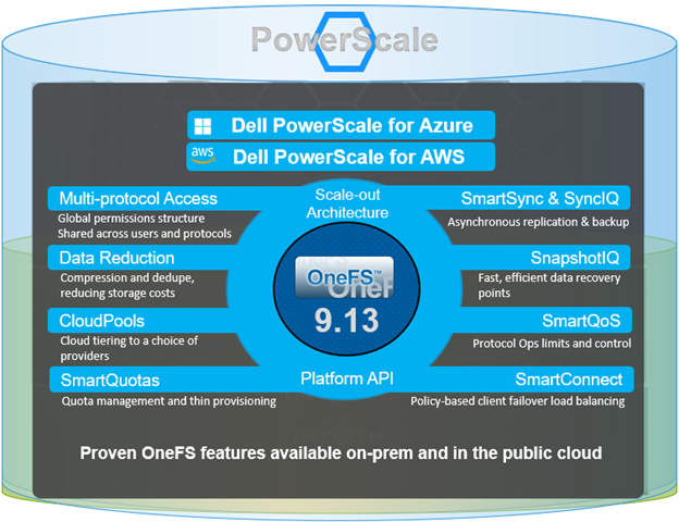
Within the OneFS 9.12 feature payload lies the introduction of support for S3 Object Locks, providing the ability to enforce write-once-read-many (WORM) protection on objects, ensuring the immutability of critical data to protect against accidental or malicious deletions. Object deletion or modification can be prevented for a defined period (or indefinitely), ensuring data integrity and allowing enterprises, such as financial institutions, to meet regulatory requirements for data retention.
But first some background. PowerScale OneFS has provided native support for the AWS S3 object API for several years now, as part of its suite of unstructured data access protocols. This integration enables OneFS clusters to support hybrid workloads that interact with the same underlying dataset using both traditional file-based protocols—such as NFS, HDFS, or SMB—and object-based access via S3. Data written through one protocol can be seamlessly accessed through another, allowing for flexible and efficient data workflows.
At the file system level, S3 objects and buckets are represented as files and directories. As a result, OneFS data services—including snapshots, replication, WORM (Write Once Read Many) immutability, and tiering—are fully integrated and available to both file and object workloads. Identity management, permissions enforcement, and access control policies are consistently applied across both access paradigms, ensuring unified security and governance.
This dual-protocol capability allows applications and workloads to access the same data through either file or object interfaces without requiring data duplication, migration, or transformation. This significantly simplifies data management and reduces operational overhead, particularly in environments with diverse access requirements.
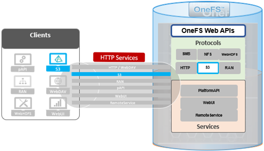
To meet enterprise security and compliance standards, OneFS supports HTTPS/TLS for encrypted data transmission. The S3 protocol is implemented as a first-class citizen within OneFS, delivering performance characteristics comparable to those of the SMB protocol.
By default, the S3 service listens on port 9020 for HTTP and port 9021 for HTTPS. These ports are configurable to accommodate specific deployment requirements, if required.
In OneFS 9.12, the S3 protocol sees the introduction of two key security enhancements:
- S3 Object Lock
- S3 Bucket Lock
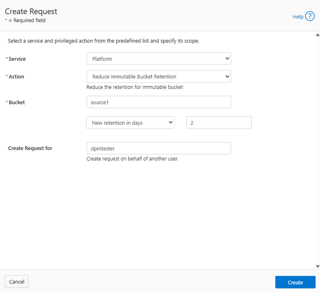
The Object Lock feature is an implementation of Amazon S3’s Object Lock functionality within the PowerScale S3 server that’s built implemented on top of the OneFS SmartLock feature within the file system. When configured, it allows individual objects to be locked, preventing their deletion, modification, or movement until their retention period expires. Retention is configured on a per-object basis, and users with the ‘ISI_PRIV_IFS_BYPASS_RETENTION’ privilege can reduce the retention period or delete locked objects.
# isi auth privileges | grep -i retention

ISI_PRIV_IFS_BYPASS_RETENTION                                            Bypass the retention setting of WORM committed files
Without such privileges, locked objects remain immutable until the retention period concludes. Note that OneFS S3 Object Lock does not support legal hold and compliance retention mode.
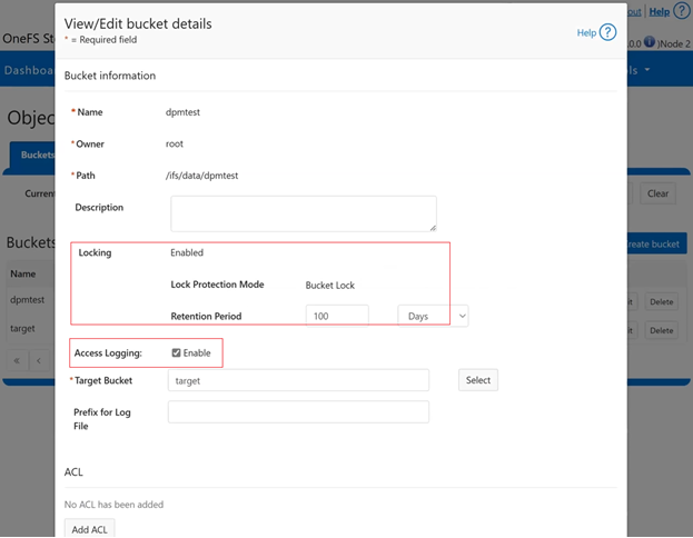
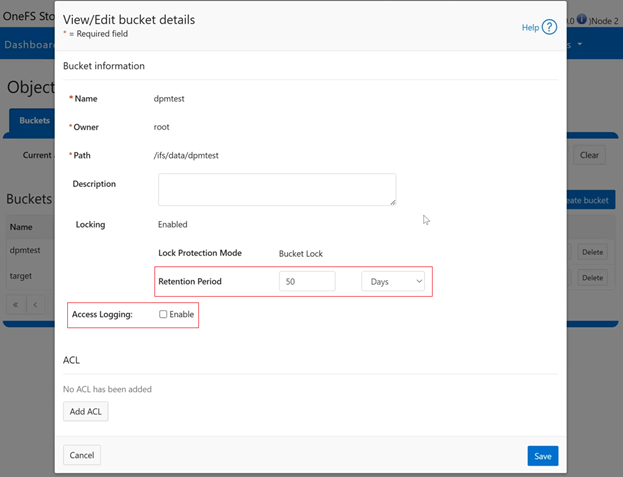
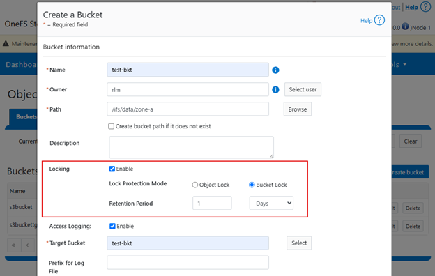
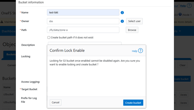
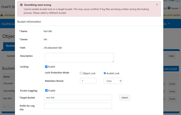
In contrast, Bucket Lock enforces immutability at the bucket level. Under this model, retention periods are not set per-object but are instead defined for the entire bucket. Any changes to the retention period apply uniformly to all objects within the bucket. Once Bucket Lock is enabled, it cannot be disabled or converted to Object Lock. Additionally, privileged deletion of locked objects is not supported under Bucket Lock. Objects can only be deleted once the bucket-level retention period has expired or has been explicitly reduced.
S3 object and bucket locking in OneFS has a slightly esoteric terminology, including the following abbreviations and definitions:
| Term |
Description |
| Bucket |
An S3 term that refers to a container of S3 objects. For OneFS, it can be mapped to top level directory containing files. |
| Bucket Policy |
Set of defined rules in S3 that govern which user will access which bucket or object. Supports regex and allows granular controls. |
| Compliance Mode |
Stricter mode for S3 object locked file. No one can delete/modify an object locked file. Similar to compliance mode of WORM. |
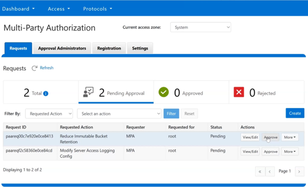
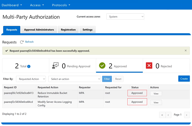
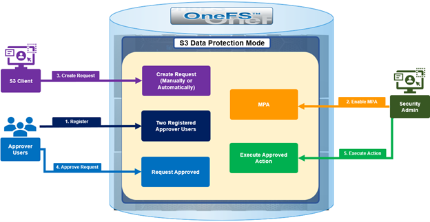
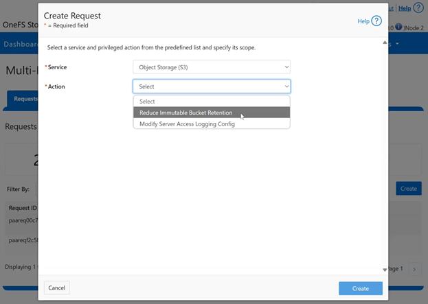
| Data Protection Mode |
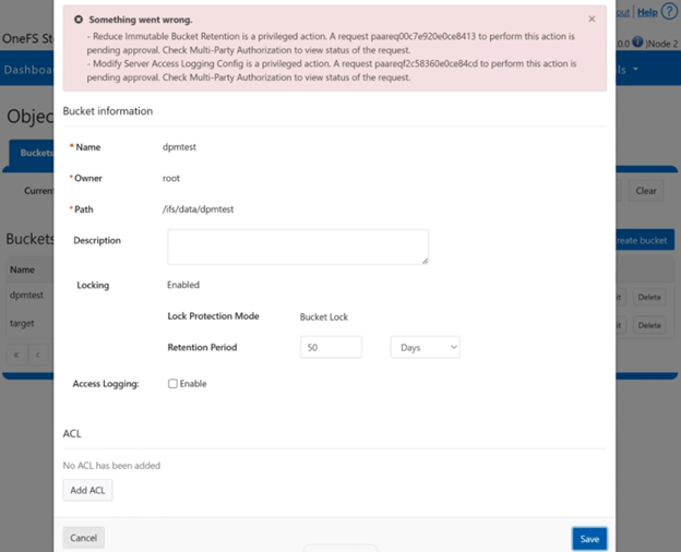
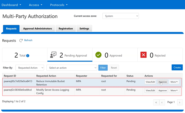
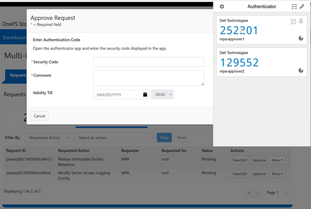
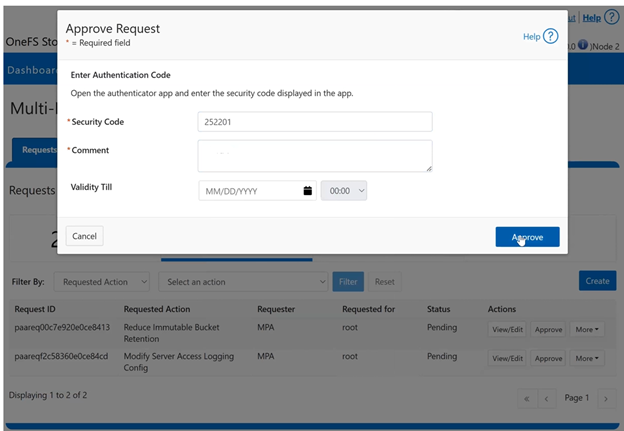
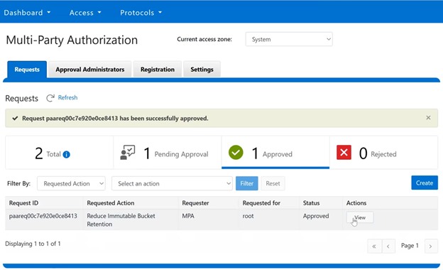
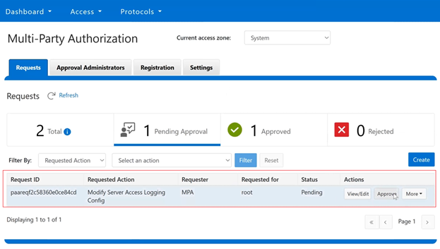
In this mode, privileged users need Multi-party Authorization (MPA) to delete an S3 object locked file or to lower file retention in GOVERNANCE mode. |
| Default Retention |
The default retention period associated with a bucket. Any new object within the bucket will inherit this retention period. |
| Governance Mode |
Regular mode for S3 object locked file. ‘Privileged Users’ can delete locked files. Similar to “enterprise” mode of WORM |
| Legal Hold |
When an S3 object is under legal hold, it remains locked until it is unlocked by a privileged user. No retention period is required. |
| Object |
An S3 term that refers to a blob that contains data. For OneFS, it can be mapped to a file. |
| Object Lock |
A feature in Amazon S3 that allows users to lock objects for a duration. When locked, files cannot be modified/deleted. |
| Object Versioning |
In S3, any modification of an S3 object creates a new version of the object. The new version can have its own Object Lock configuration. |
| Privileged Users |
Users who have special permissions/privileges, allowing them to delete files that are locked under some circumstances. |
| Retention Period |
Time during which a file or object is locked. After this period, the file can be deleted if required |
| WORM Domain |
A directory that is enabled for WORM |
| WORM File |
A file that is locked or committed for WORM. A WORM file cannot be modified or deleted. |
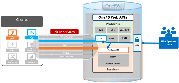
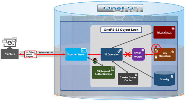
Architecturally, OneFS S3 consists of six main components, which are:
| Component |
Description |
| FS Layer |
The kernel FS layer that performs WORM actions. All WORM domains and files are managed at this layer. |
| Iomgr |
The platform agnostic IO manager that is connected to protocol heads. Exposes IO APIs that perform platform specific operations through file system drivers created for each platform. Object locking is only supported in OneFS file system driver. |
| CLI/WebUI/pAPI |
The entry points for configuration S3 object locking as well as enabling/disabling object locking. PAPI interacts with S3 protocol head for S3 operation and Tardis for setting/getting configuration. |
| S3 Clients |
Clients connected to OneFS cluster for S3 operations. Requests from S3 clients are in the form of ReST APIs. These clients can be local to the node or can be external entity. |
| S3 Protocol Head |
The Powerscale S3 server. Processes requests from S3 clients and performs required actions. |
| Tardis |
Stores the configuration of object locks. Every configuration item for object locking is stored inside a bucket entry under S3 namespace. |
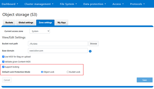
Both Object Lock and Bucket Lock are managed through a new locking domain based on the WORM (Write Once Read Many) domain. Unlike AWS S3, versioning is neither required nor supported in this implementation. Retention date calculations rely on the OneFS compliance clock, which must be enabled before these features can be used.
When configuring Object Lock, administrators can define a default retention period at the bucket level. This default applies to newly added objects unless overridden via the S3 API.
| S3 API Endpoint |
Description |
| CreateBucket |
Creates a regular S3 bucket.
• If header parameter ‘x-amz-bucket-object-lock-enabled’ is present, bucket is object lock enabled.
• If header parameter ‘isi-lock-protection-mode’ is present for specifying lock mode type. |
| PutObjectLockConfiguration |
Enables object lock on a regular bucket. Sets bucket default retention. Sets lock-protection-mode. |
| GetObjectLockConfiguration |
Gets current object lock information with bucket retention for a bucket |
| PutObjectRetention |
Locks a regular object with given retention period. Also used to extend/lower retention period of a locked object.
Note that this is a disabled and invalid operation for Bucket Lock buckets. |
Within an Object Lock-enabled bucket, objects may be either locked or unlocked. In contrast, Bucket Lock applies a dynamic retention model, where the retention period is calculated from each object’s creation time using the bucket-level setting.
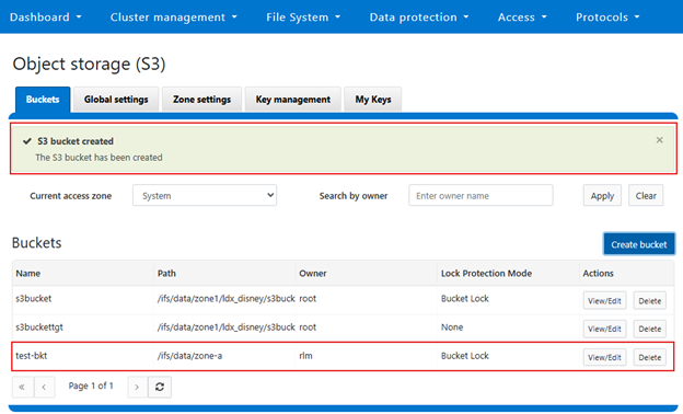
Configuration of both Object Lock and Bucket Lock is supported through the OneFS CLI, WebUI, and platform API (pAPI). The S3 API has been extended to support these features.
| S3 API Endpoint |
Description |
| CreateBucket |
Creates a regular S3 bucket.
• If header parameter ‘x-amz-bucket-object-lock-enabled’ is present, the bucket is object lock-enabled.
• If header parameter ‘isi-lock-protection-mode’ is present for specifying lock mode type. |
| PutObjectLockConfiguration |
Enables object lock on a regular bucket. Sets bucket default retention. Sets lock-protection-mode. |
| GetObjectLockConfiguration |
Gets current object lock information with bucket retention for a bucket |
| PutObjectRetention |
Locks a regular object with a given retention period. Also used to extend/lower the retention period of a locked object.
Note that PutObjectRetention is a disabled and invalid operation for Bucket Lock buckets. |
For example, the CreateBucket operation now accepts the ‘x-amz-bucket-object-lock-enabled’ flag. Additionally, a custom header, ‘isi-lock-protection-mode’, allows the lock mode type to be specified. If this header is omitted, the system defaults to the zone’s configured protection mode.
The ‘HeadObject’ and ‘GetObject’ operations return retention metadata when locking is enabled. The ‘DeleteObject’ and ‘DeleteObjects’ operations support the ‘x-amz-bypass-governance-retention’ header, which is applicable only in Object Lock mode and requires the appropriate privileges. For object creation operations such as ‘PutObject’, ‘CopyObject’, and multipart uploads, the ‘x-amz-object-lock-retain-until-date’ header can be used to set object-level retention. This header is only valid in Object Lock mode, as Bucket Lock relies solely on the bucket-level retention setting.
New API operations have also been introduced. Specifically, PutObjectLockConfiguration’ and ‘GetObjectLockConfiguration’ allow administrators to manage bucket-level lock settings and default retention values.
| S3 API Endpoint |
Description |
| PutObjectLockConfiguration |
Enables object lock or modify retention settings on a bucket. Custom header. |
| GetObjectLockConfiguration |
Gets current object lock information with bucket retention for a bucket. |
| GetObjectRetention |
Gets the retention period of a locked object.
|
| PutObjectRetention |
Locks a regular object with a given retention period. Also used to extend/lower the retention period of a locked object.
Note that PutObjectRetention is a disabled and invalid operation for Bucket Lock buckets. |
At the object level, ‘PutObjectRetention’ and ‘GetObjectRetention’ enable setting and retrieving retention information. Reducing an object’s retention period requires the ‘x-amz-bypass-governance-retention’ header and the appropriate privileges. These operations are not supported under Bucket Lock.
- GetObjectLockConfiguration
The new ‘GetObjectLockConfiguration’ S3 endpoint retrieves the current object lock configuration of a bucket. If object lock is not enabled for the bucket, an HTTP 400 error code will be returned.
Request
GET /?object-lock HTTP/1.1
Host: <Bucket-address>
x-amz-expected-bucket-owner: Owner
Response
HTTP/1.1 200
<?xml version="1.0" encoding="UTF-8"?>
<ObjectLockConfiguration>
<ObjectLockEnabled>string</ObjectLockEnabled>
<Rule>
<DefaultRetention>
<Days>integer</Days>
<Mode>string</Mode>
<Years>integer</Years>
</DefaultRetention>
</Rule>
</ObjectLockConfiguration>
If object lock is enabled on a bucket the ‘ObjectLockEnabled’ parameter, the ‘Mode’ field is set to either ‘GOVERNANCE’ or ‘COMPLIANCE’, and ‘DefaultRetention’ period is expressed in either in Days or Years (but not both).
- PutObjectLockConfiguration
The ‘PutObjectLockConfiguration’ endpoint sets object lock functionality on an existing bucket. It is also used to set the ‘Mode’ and ‘DefaultRetention’ period on the bucket. Note that only the bucket owner can perform this operation.
Request
PUT /?object-lock HTTP/1.1
Host: <Bucket-address>
x-amz-expected-bucket-owner: Owner
<ObjectLockConfiguration>
<ObjectLockEnabled>string</ObjectLockEnabled>
<Rule>
<DefaultRetention>
<Days>integer</Days>
<Mode>string</Mode>
<Years>integer</Years>
</DefaultRetention>
</Rule>
</ObjectLockConfiguration>
If enabled, ‘ObjectLockEnabled’ activates object locking on bucket. Once enabled, object locking cannot be disabled. The ‘DefaultRetention’ parameter is set for the bucket, but this can also be manually configured, and expressed in either days or years. A maximum value of 100 years is permitted, while a value of 0 indicates no retention. The ‘mode’ parameter is either ‘GOVERNANCE’ or ‘COMPLIANCE’, while noting that only ‘GOVERNANCE’ mode is supported when a cluster is in enterprise state.
Response
HTTP/1.1 200
The ‘GetObjectRetention’ endpoint fetches the retention date associated with an object locked S3 object. If the object is not locked, the API returns an HTTP 400 error.
Request
GET /{Key}?retention HTTP/1.1
Host: <Bucket-location>
x-amz-expected-bucket-owner: ExpectedBucketOwner
The mandatory ‘Key’ field contains the S3 object key. Also, unlike AWS, OneFS 9.12 does not support the ‘VersionId’ parameter in this operation.
Response
HTTP/1.1 200
<?xml version="1.0" encoding="UTF-8"?>
<Retention>
<Mode>string</Mode>
<RetainUntilDate>timestamp</RetainUntilDate>
</Retention>
The ‘Mode’ field in the above is the bucket mode, and individual S3 objects share their common bucket mode. Also,
the ‘RetainUntilDate’ field contains the retention period of the object, of which the format type is a timestamp.
The ‘PutObjectRetention’ endpoint sets the retention period of an S3 object, returning an error if object lock is not enabled on bucket.
Request
PUT /{Key}?retention HTTP/1.1
Host: <Bucket-location>
x-amz-expected-bucket-owner: ExpectedBucketOwner
x-amz-bypass-governance-retention: BypassGovernanceRetention
Content-MD5: ContentMD5
<?xml version="1.0" encoding="UTF-8"?>
<Retention xmlns="http://s3.amazonaws.com/doc/2006-03-01/">
<Mode>string</Mode>
<RetainUntilDate>timestamp</RetainUntilDate>
</Retention>
The ‘key’ field contains the S3 object key, and is required. Unlike AWS, ‘VersionId’ is not supported in the OneFS 9.12 S3 object lock implementation. If setting retention that is lower than current retention period of the object, the request must have the URI parameter ‘x-amz-bypass-governance-retention’ set to ‘BypassGovernanceRetention’. Additionally, ‘mode’ field must match the bucket mode, and ‘RetainUntilDate’ be a future timestamp.
Response
HTTP/1.1 200
In the next article in this series, we’ll take a closer look at the configuration and management of OneFS S3 object and bucket locking.