OneFS Job Execution and Node Exclusion

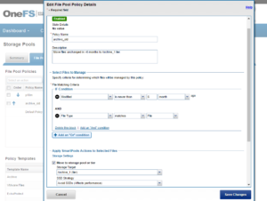
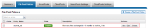
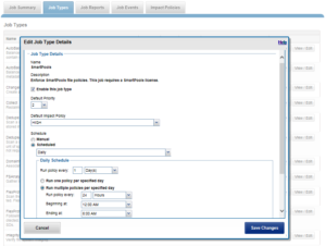
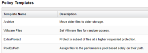
The majority of the OneFS job engine’s jobs have no default schedule and are typically manually started by a cluster administrator or process. Other jobs such as FSAnalyze, MediaScan, ShadowStoreDelete, and SmartPools, are normally started via a schedule. The job engine can also initiate certain jobs on its own. For example, if the SnapshotIQ process detects that a snapshot has been marked for deletion, it will automatically queue a SnapshotDelete job.

The Job Engine will also execute jobs in response to certain system event triggers. In the case of a cluster group change, for example the addition or subtraction of a node or drive, OneFS automatically informs the job engine, which responds by starting a FlexProtect job. The coordinator notices that the group change includes a newly-smart-failed device and then initiates a FlexProtect job in response.

Job administration and execution can be controlled via the WebUI, CLI, or platform API and a job can be started, stopped, paused and resumed, and this is managed via the job engines’ check-pointing system. For each of these control methods, additional administrative security can be configured using roles-based access control (RBAC).

The job engine’s impact control and work throttling mechanism is able to limit the rate at which individual jobs can run. Throttling is employed at a per-manager process level, so job impact can be managed both granularly and gracefully.

Every twenty seconds, the coordinator process gathers cluster CPU and individual disk I/O load data from all the nodes across the cluster. The coordinator uses this information, in combination with the job impact configuration, to decide how many threads may run on each cluster node to service each running job. This can be a fractional number, and fractional thread counts are achieved by having a thread sleep for a given percentage of each second.

Using this CPU and disk I/O load data, every sixty seconds the coordinator evaluates how busy the various nodes are and makes a job throttling decision, instructing the various job engine processes as to the action they need to take. This enables throttling to be sensitive to workloads in which CPU and disk I/O load metrics yield different results. Additionally, there are separate load thresholds tailored to the different classes of drives utilized in OneFS powered clusters, from capacity optimized SATA disks to flash-based SSDs.

However, up through OneFS 9.2, a job engine job was an all or nothing entity. Whenever a job ran, it involved the entire cluster – regardless of individual node type, load, or condition. As such, any nodes that were overloaded or in a degraded state could still impact the execution ability of the job at large.

To address this, OneFS 9.3 provides the capability to exclude one or more nodes from participating in running a job. This allows the temporary removal of any nodes with high load, or other issues, from the job execution pool so that jobs do not become stuck. Configuration is via the OneFS CLI and gconfig and is global, such that it applies to all jobs on startup. However, the exclusion configuration is not dynamic, and once a job is started with the final node set, there is no further reconfiguration permitted. So if a participant node is excluded, it will remain excluded until the job has completed. Similarly, if a participant needs to be excluded, the current job will have to be cancelled and a new job started. Any nodes can be excluded, including the node running the job engine’s coordinator process. The coordinator will still monitor the job, it just won’t spawn a manager for the job.

The list of participating nodes for a job are computed in three phases:

  1. Query the cluster’s GMP group.
  2. Call to job.get_participating_nodes to get a subset from the gmp group
  3. Remove the nodes listed in core.excluded_participants from the subset.

The CLI syntax for configuring an excluded nodes list on a cluster is as follows (in this example, excluding nodes one through three):

# isi_gconfig –t job-config core.excluded_participants="{1,2,3}"

The ‘excluded_participants’ are entered as a comma-separated devid value list with no spaces, specified within parentheses and double quotes.

Note that it is the node’s device ID (devid) which is required in the above command, and this is not always the same as the node number (LNN). The following command will report both the LNN and corresponding devid:

# isi_nodes %{lnn} , %{id}

All excluded nodes must be specified in full, since there’s no aggregation. Note that, while the excluded participant configuration will be displayed via gconfig, it is not reported as part of the ‘sysctl efs.gmp.group’ output.

A job engine node exclusion configuration can be easily reset to avoid excluding any nodes by assigning the “{}” value.

# isi_gconfig –t job-config core.excluded_participants="{}"

A ‘core.excluded_participant_percent_warn’ parameter defines the maximum percentage of removed nodes.

# isi_gconfig -t job-config core.excluded_participant_percent_warn

core.excluded_participant_percent_warn (uint) = 10

This parameter defaults to 10%, above which a CELOG event warning is generated.

As many nodes as desired can be removed from the job group. CELOG informational event will notify of removed nodes. If too many nodes have been removed, (gconfig parameter sets too many node threshold) CELOG will fire a warning event. If some nodes are removed but they’re not part of the GMP group, a different warning event will trigger.

If all nodes are removed, a CLI/pAPI error will be returned, the job will fail, and a CELOG warning will fire. For example:

# isi job jobs start LinCount

Job operation failed: The job had no participants left. Check core.excluded_participants setting and make sure there is at least one node to run the job:  Invalid argument

# isi job status

10   LinCount         Failed    2021-10-24T:20:45:23

------------------------------------------------------------------

Total: 9

Note, however, that the following core system maintenance jobs will continue to run across all nodes in a cluster even if a node exclusion has been configured:

  • AutoBalance
  • Collect
  • FlexProtect
  • MediaScan
  • MultiScan

OneFS 9.3 Introduction

Arriving hot on the heels of the PowerStore H700 & H7000 hybrid chassis and A300 & A300 archive platforms that debuted last month, the new PowerScale OneFS 9.3 release shipped on Monday, 18th October 2021. This new 9.3 release brings with it an array of new features and functionality, including:

Feature Info
NVMe SED support for PowerScale All-flash ·         FIPS-certified Self-Encrypting Drives (SEDs) support for PowerScale F600 & F900 nodes
Writable Snapshots ·         Enables the creation and management of a space and time efficient, modifiable copy of a regular OneFS snapshot.
NFS v4.1 and v4.2 Support ·         Connectivity support for versions 4.1 and 4.2 of the NFS file access protocol.
Long filename support ·         Provision for file names up to 1024 bytes, allowing support for long names in UTF-8 multi-byte character sets.
Inline data in inodes ·         Data efficiency feature allowing a small file’s data to be stored in unused space within its inode block.
HDFS ACLs ·         Provide support for HDFS-4685 access control lists, allowing users to manage permissions on their datasets from Hadoop clients.
Job engine exclusions ·         Allow Job engine jobs to be run on a defined subset of a cluster’s nodes.
CloudPools Recall ·         Improved CloudPools file recall & rehydrate performance.
Safe SMB client disconnects ·         Allows SMB clients the opportunity to flush their caches prior to being disconnected.
S3 protocol enhancements ·         Added support for S3 chunked upload, multi-object delete, and non-slash delimiters for lists.

The new OneFS 9.3 code is available on the Dell EMC Online Support site as both a  reimage file for configuring new clusters with 9.3, and an upgrade package for legacy clusters.

We’ll also be taking a deeper look at  these new OneFS 9.3 features in blog articles over the course of the next few weeks.

OneFS Netlogger

Among the useful data and network analysis tools that OneFS provides is the isi_netlogger utility. Netlogger captures IP traffic over a period of time for network and protocol analysis.

Under the hood, isi_netlogger is a python wrapper around the ubiquitous tcpdump utility. Netlogger can be run either from the OneFS command line or WebUI.

For example, from the WebUI, browse to Cluster management > Diagnostics:

Alternatively, from the OneFS CLI, the isi_netlogger command captures traffic on interface (‘-i’) over a timeout period of minutes (‘-t’), and stores a specified number of log files,as defined by the keep_count, or ‘-k’ parameter.

Using the ‘-b’ bpf buffer size option will temporarily change the default buffer size while netlogger is running. Netlogger’s log files are stored by default under /ifs/netlog/<node_name>.

Here’s the basic syntax of the tool:

isi_netlogger [-c launch clustered mode (run on all nodes)]

              [-n run on specified nodes (ex: -n 1,3)]

              [-d run as daemon]

              [-q quiet mode (redirect output to logs)]

              [-k keep_count of logs (default 3, to keep all logs use 0)]

              [-t timeout (default 10) ]

              [-s snaplen (default 320) ]

              [-b bpf buffer size in bytes, KB, or MB (end with 'k' or 'm') ]

              [-i interface name[,..] | all (ex: -i em0 or -i em0,em1 or -i all)]

              [-a ARP packets included. Normally filtered out ]

              [-p print out the tcpdump command ]

              [-z do not bundle capture files (default bundling is done)]

              [-- tcpdump filtering options]

The WebUI can also be used to configure the netlogger parameters under Cluster management > Diagnostics > Netlogger settings:

Be aware that ‘isi_for_array isi_netlogger’ will consume significant cluster resources. When running the tool on a production cluster, be cognizant of the effect on the system.

When the command has completed, the capture file(s) are stored under the /ifs/netlog directory.

The following command can also be used to incorporate netlogger output files into an isi_gather_info bundle:

# isi_gather_info -n [node#] -f /ifs/netlog

To capture on multiple nodes of the cluster, the netlogger command can be prefixed by the versatile isi_for_array utility:

# isi_netlogger -n 2,3 -t 5 -k 864 -s 256

The command syntax above will create five minute incremental files on nodes 2 and 3, using a snaplength of 256 bytes, which will capture the first 256 bytes of each packet. These five-minute logs will be kept for about three days and the naming convention is of the form netlog-<node_name>-<date>-<time>.pcap. For example:

# ls

/etc/netlog/lab-cluster-1/netlog-lab_cluster-1.2021-10-18_20.24.38.pcap

When using isi_netlogger, the ‘-s’ flag needs to be set appropriately based on the protocol being to capture the right amount of detail in the packet headers and/or payload. Or, if you want the entire contents of every packet, a value of zero (‘-s 0’) can be used.

The default snaplength for netlogger is to use a snaplen of 320 bytes per packet, which is usually enough for most protocols.

However, for SMB, a snaplength of 512 is sometimes required. However, depending on a node’s traffic quantity, a snaplen of 0 (eg: capture whole packet) can potentially overwhelm the nic driver.

All the output gets written to files under /ifs/netlog and the default capture time is ten minutes (‘-t 10’).

Filters can be applied to the  filter to the end to constrain traffic to/from certain hosts or protocols. For example, to limit output to traffic between client 10.10.10.1:

# isi_netlogger -t 5 -k 864 -s 256 -- host 10.10.10.1

Or to capture NFS traffic only, filter on port 2049:

# isi_netlogger -- port 2049

Or multiple ports:

# isi_netlogger -- port 2345 or port 5432

To capture from a non-standard interface can sometime require a bit of creativity:

# isi_netlogger -p -t 5 -k 864 -s 256 -a -- " -i vlan0 host 192.168.10.1"

The -p flag to print out the tcpdump command it is running. And, essentially, anything following a double dash flag ‘–‘ is passed as a normal tcpdump filter/option.

To capture across differing interface names across the cluster:

# isi_netlogger -i \`ifconfig |grep -B2 'inet <ip_addr>.' | grep flags= | awk -F: '{ print $1 }'\` -s 0 -a

Where <ip_addr> is as much of the public IP address that is common across all the nodes. For example “192.” or “192.168.”.

To stop netlogger before a command has completed, a simple ‘isi_for_array killall tcpdump’ can be used to terminate any active tcpdump/netlogger sessions across a cluster. If any processes do remain after this, these can all be killed with a command along the lines of:

# isi_for_array -s "kill -9 \`ps auxw|grep netlog|grep -v grep|awk {'print \$2'}\`;killall -9 tcpdump"

PowerScale Gen6 Chassis Hardware Resilience

In this article, we’ll take a quick look at the OneFS journal and boot drive mirroring functionality in PowerScale chassis-based hardware:

PowerScale Gen6 platforms, such as the H700/7000 and A300/3000, stores the local filesystem journal and its mirror in the DRAM of the battery backed compute node blade.  Each 4RU Gen 6 chassis houses four nodes. These nodes comprise a ‘compute node blade’ (CPU, memory, NICs), plus  drive containers, or sleds, for each.

A node’s file system journal is protected against sudden power loss or hardware failure by OneFS’ journal vault functionality – otherwise known as ‘powerfail memory persistence’ (PMP). PMP automatically stores the both the local journal and journal mirror on a separate flash drive across both nodes in a node pair:

This journal de-staging process is known as ‘vaulting’, during which the journal is protected by a dedicated battery in each node until it’s safely written from DRAM to SSD on both nodes in a node-pair. With PMP, constant power isn’t required to protect the journal in a degraded state since the journal is saved to M.2 flash, and mirrored on the partner node.

So, the mirrored journal is comprised of both hardware and software components, including the following constituent parts:

Journal Hardware Components

  • System DRAM
  • 2 Vault Flash
  • Battery Backup Unit (BBU)
  • Non-Transparent Bridge (NTB) PCIe link to partner node
  • Clean copy on disk

Journal Software Components

  • Power-fail Memory Persistence (PMP)
  • Mirrored Non-volatile Interface (MNVI)
  • IFS Journal + Node State Block (NSB)
  • Utilities

Asynchronous DRAM Refresh (ADR) preserves RAM contents when the operating system is not running. ADR is important for preserving RAM journal contents across reboots, and it does not require any software coordination to do so.

The journal vault feature encompasses the hardware, firmware, and operating system support that ensure the journal’s contents are preserved across power failure. The mechanism is similar to the NVRAM controller on previous generation nodes, but does not use a dedicated PCI card.

On power failure, the PMP vaulting functionality is responsible for copying both the local journal and the local copy of the partner node’s journal to persistent flash. On restoration of power, PMP is responsible for restoring the contents of both journals from flash to RAM, and notifying the operating system.

A single dedicated flash device is attached via M.2 slot on the motherboard of the node’s compute module, residing under the battery backup unit (BBU) pack. To be serviced, the entire compute module must be removed.

If the M.2 flash needs to be replaced for any reason, it will be properly partitioned and the PMP structure will be created as part of arming the node for vaulting.

The battery backup unit (BBU), when fully charged, provides enough power to vault both the local and partner journal during a power failure event.

A single battery is utilized in the BBU, which also supports back-to-back vaulting.

On the software side, the journal’s Power-fail Memory Persistence (PMP) provides an equivalent to the NVRAM controller‘s vault/restore capabilities to preserve Journal. The PMP partition on the M.2 flash drive provides an interface between the OS and firmware.

If a node boots and its primary journal is found to be invalid for whatever reason, it has three paths for recourse:

  • Recover journal from its M.2 vault.
  • Recover journal from its disk backup copy.
  • Recover journal from its partner node’s mirrored copy.

The mirrored journal must guard against rolling back to a stale copy of the journal on reboot. This necessitates storing information about the state of journal copies outside the journal. As such, the Node State Block (NSB) is a persistent disk block that stores local and remote journal status (clean/dirty, valid/invalid, etc), as well as other non-journal information. NSB stores this node status outside the journal itself, and ensures that a node does not revert to a stale copy of the journal upon reboot.

Here’s the detail of an individual node’s compute module:

Of particular note is the ‘journal active’ LED, which is displayed as a white ‘hand icon’.

When this white hand icon is illuminated, it indicates that the mirrored journal is actively vaulting, and it is not safe to remove the node!

There is also a blue ‘power’ LED, and a yellow ‘fault’ LED per node. If the blue LED is off, the node may still be in standby mode, in which case it may still be possible to pull debug information from the baseboard management controller (BMC).

The flashing yellow ‘fault’ LED has several state indication frequencies:

Blink Speed Blink Frequency Indicator
Fast blink ¼ Hz BIOS
Medium blink 1 Hz Extended POST
Slow blink 4 Hz Booting OS
Off Off OS running

The mirrored non-volatile interface (MNVI) sits below /ifs and above RAM and the NTB, provides the abstraction of a reliable memory device to the /ifs journal. MNVI is responsible for synchronizing journal contents to peer node RAM, at the direction of the journal, and persisting writes to both systems while in a paired state. It upcalls into the journal on NTB link events, and notifies the journal of operation completion (mirror sync, block IO, etc).

For example, when rebooting after a power outage, a node automatically loads the MNVI. It then establishes a link with its partner node and synchronizes its journal mirror across the PCIe Non-Transparent Bridge (NTB).

Prior to mounting /ifs, OneFS locates a valid copy of the journal from one of the following locations in order of preference:

Order Journal Location Description
1st Local disk A local copy that has been backed up to disk
2nd Local vault A local copy of the journal restored from Vault into DRAM
3rd Partner node A mirror copy of the journal from the partner node

If the node was shut down properly, it will boot using a local disk copy of the journal.  The journal will be restored into DRAM and /ifs will mount. On the other hand, if the node suffered a power disruption the journal will be restored into DRAM from the M.2 vault flash instead (the PMP copies the journal into the M.2 vault during a power failure).

In the event that OneFS is unable to locate a valid journal on either the hard drives or M.2 flash on a node, it will retrieve a mirrored copy of the journal from its partner node over the NTB.  This is referred to as ‘Sync-back’.

Note: Sync-back state only occurs when attempting to mount /ifs.

On booting, if a node detects that its journal mirror on the partner node is out of sync (invalid), but the local journal is clean, /ifs will continue to mount.  Subsequent writes are then copied to the remote journal in a process known as ‘sync-forward’.

Here’s a list of the primary journal states:

Journal State Description
Sync-forward State in which writes to a journal are mirrored to the partner node.
Sync-back Journal is copied back from the partner node. Only occurs when attempting to mount /ifs.
Vaulting Storing a copy of the journal on M.2 flash during power failure. Vaulting is performed by PMP.

During normal operation, writes to the primary journal and its mirror are managed by the MNVI device module, which writes through local memory to the partner node’s journal via the NTB. If the NTB is unavailable for an extended period, write operations can still be completed successfully on each node. For example, if the NTB link goes down in the middle of a write operation, the local journal write operation will complete. Read operations are processed from local memory.

Additional journal protection for Gen 6 nodes is provided by OneFS’ powerfail memory persistence (PMP) functionality, which guards against PCI bus errors that can cause the NTB to fail.  If an error is detected, the CPU requests a ‘persistent reset’, during which the memory state is protected and node rebooted. When back up again, the journal is marked as intact and no further repair action is needed.

If a node looses power, the hardware notifies the BMC, initiating a memory persistent shutdown.  At this point the node is running on battery power. The node is forced to reboot and load the PMP module, which preserves its local journal and its partner’s mirrored journal by storing them on M.2 flash.  The PMP module then disables the battery and powers itself off.

Once power is back on and the node restarted, the PMP module first restores the journal before attempting to mount /ifs.  Once done, the node then continues through system boot, validating the journal, setting sync-forward or sync-back states, etc.

During boot, isi_checkjournal and isi_testjournal will invoke isi_pmp. If the M.2 vault devices are unformatted, isi_pmp will format the devices.

On clean shutdown, isi_save_journal stashes a backup copy of the /dev/mnv0 device on the root filesystem, just as it does for the NVRAM journals in previous generations of hardware.

If a mirrored journal issue is suspected, or notified via cluster alerts, the best place to start troubleshooting is to take a look at the node’s log events. The journal logs to /var/log/messages, with entries tagged as ‘journal_mirror’.

The following new CELOG events have also been added in OneFS 8.1 for cluster alerting about mirrored journal issues:

CELOG Event Description
HW_GEN6_NTB_LINK_OUTAGE Non-transparent bridge (NTP) PCIe link is unavailable
FILESYS_JOURNAL_VERIFY_FAILURE No valid journal copy found on node

Another reliability optimization for the Gen6 platform is boot mirroring. Gen6 does not use dedicated bootflash devices, as with previous generation nodes. Instead, OneFS boot and other OS partitions are stored on a node’s data drives. These OS partitions are always mirrored (except for crash dump partitions). The two mirrors protect against disk sled removal. Since each drive in a disk sled belongs to a separate disk pool, both elements of a mirror cannot live on the same sled.

The boot and other OS partitions are  8GB and reserved at the beginning of each data drive for boot mirrors. OneFS automatically rebalances these mirrors in anticipation of, and in response to, service events. Mirror rebalancing is triggered by drive events such as suspend, softfail and hard loss.

The following command will confirm that boot mirroring is working as intended:

# isi_mirrorctl verify

When it comes to smartfailing nodes, here are a couple of other things to be aware of with mirror journal and the Gen6 platform:

  • When you smartfail a node in a node pair, you do not have to smartfail its partner node.
  • A node will still run indefinitely with its partner missing. However, this significantly increases the window of risk since there’s no journal mirror to rely on (in addition to lack of redundant power supply, etc).
  • If you do smartfail a single node in a pair, the journal is still protected by the vault and powerfail memory persistence.

Regarding the journal’s Battery Backup Unit (BBU), later versions of OneFS and BBU firmware can generate an Cell End of Life warning. This end-of-life message (EOL) for the BBU does not indicate that the BBU is unhealthy, but rather that it’s coming up on EOL.

The battery wear percentage value indicates the amount of deterioration to the battery cell and therefore its ability hold charge.

The BBU firmware version 2.20 introduced an alert that will warns when a node is approaching End of Life (EOL) on its battery.  The report for the event will occur when battery degradation reaches a 40% threshold.

Note that a nodes will automatically transition into read-only (RO) state if the battery reaches the 50% threshold.

A cluster’s BBU firmware version can be easily determined via the following CLI syntax:

# isi upgrade cluster firmware devices | egrep "mongoose|bcc"

The command output will be similar to the following:

# isi upgrade cluster firmware devices| egrep "mongoose|bcc"
MLKbem_mongoose           ePOST  02.40                   1-4
EPbcc_infinity            ePOST  02.40                   5-8

The amount of time to go from 40% degradation to 50% degradation is also affected by the BBU firmware version. If the BBU firmware version is 1.20, the battery should take four months to go from 40% to 50% degradation
If the BBU firmware version is 2.20 or above, the battery should take 12 months to transition from 40% to 50% degradation.

Details about upgrading from BBU firmware version 1.20 to the latest supported firmware version can be found in the following KB article.

PowerScale Platform Update

In this article, we’ll take a quick peek at the new PowerScale Hybrid H700/7000 and Archive A300/3000 hardware platforms that were released last month. So the current PowerScale platform family hierarchy is as follows:

Here’s the lowdown on the new additions to the hardware portfolio:

Model Tier Drive per Chassis & Drives Max Chassis Capacity (16TB HDD) CPU per Node Memory per Node Network
H700 Hybrid/Utility Standard:

60 x 3.5” HDD

960TB CPU: 2.9Ghz, 16c Mem: 384GB FE: 100GbE

BE: 100GbE or IB

H7000 Hybrid/Utility Deep:

80 x 3.5” HDD

1280TB CPU: 2.9Ghz, 16c Mem: 384GB FE: 100GbE

BE: 100GbE or IB

A300 Archive Standard:

60 x 3.5” HDD

960TB CPU: 1.9Ghz, 6c Mem: 96GB FE: 25GbE

BE: 25GbE or IB

A3000 Archive Deep:

80 x 3.5” HDD

1280TB CPU: 1.9Ghz, 6c Mem: 96GB FE: 25GbE

BE: 25GbE or IB

The PowerScale H700 provides performance and value to support demanding file workloads. With up to 960 TB of HDD per chassis, the H700 also includes inline compression and deduplication capabilities to further extend the usable capacity

The PowerScale H7000 is a versatile, high performance, high capacity hybrid platform with up to 1280 TB per chassis. The deep chassis based H7000 is an ideal to consolidate a range of file workloads on a single platform. The H7000 includes inline compression and deduplication capabilities

On the active archive side, the PowerScale A300  combines performance, near-primary accessibility, value, and ease of use. The A300 provides between 120 TB to 960 TB per chassis and scales to 60 PB in a single cluster. The A300 includes inline compression and deduplication capabilities

PowerScale A3000: is an ideal solution for high performance, high density, deep archive storage that safeguards data efficiently for long-term retention. The A3000 stores up to 1280 TB per chassis and scales to north of 80 PB in a single cluster. The A3000 also includes inline compression and deduplication.

These new H700/7000 and A300/3000 nodes require OneFS 9.2.1, and can be seamlessly added to an existing cluster, offering the full complement of OneFS data services including snapshots, replication, quotas, analytics, data reduction, load balancing, and local and cloud tiering. All also contain SSD

Unlike the all-flash PowerScale F900, F600, and F200 stand-alone nodes, which required a minimum of 3 nodes to form a cluster, a single chassis of 4 nodes is required to create a cluster, with support for both InfiniBand and Ethernet backend network connectivity.

Each F700/7000 and A300/3000 chassis contains four compute modules (one per node), and five drive containers, or sleds, per node. These sleds occupy bays in the front of each chassis, with a node’s drive sleds stacked vertically:

The drive sled is a tray which slides into the front of the chassis, and contains between three and four 3.5 inch drives in an H700/0 or A300/0, depending on the drive size and configuration of the particular node. Both regular hard drives or self-encrypting drives (SEDs) are available  in 2,4, 8, 12, and 16TB capacities.

Each drive sled has a white ‘not safe to remove’ LED on its front top left, as well as a blue power/activity LED, and an amber fault LED.

The compute modules for each node are housed in the rear of the chassis, and contain CPU, memory, networking, and SSDs, as well as power supplies. Nodes 1 & 2 are a node pair, as are nodes 3 & 4. Each node-pair shares a mirrored journal and two power supplies:

Here’s the detail of an individual compute module, which contains a multi core Cascade Lake CPU, memory, M2 flash journal, up to two SSDs for L3 cache, six DIMM channels, front end 40/100 or 10/25 Gb ethernet, 40/100 or 10/25 Gb ethernet or Infiniband, an ethernet management interface, and power supply and cooling fans:

On the front of each chassis is an LCD front panel control with back-lit buttons and 4 LED Light Bar Segments – 1 per Node. These LEDs typically display blue for normal operation or yellow to indicate a node fault. This LCD display is hinged so it can be swung clear of the drive sleds for non-disruptive HDD replacement, etc:

So, in summary, the new PowerScale hardware delivers:

  • More Power
    • More cores, more memory and more cache
    • A300/3000 up to 2x faster than previous generation (A200/2000)
  • More Choice
    • 100GbE, 25GbE and Infiniband options for cluster interconnect
    • Node compatibility for all hybrid and archive nodes
    • 30TB to 320TB per rack unit
  • More Value
    • Inline data reduction across the PowerScale family
    • Lowest $/GB and most density among comparable solutions

OneFS Path-based File Pool Policies

As we saw in the previous article, when data is written to the cluster, SmartPools determines which pool to write to based upon either path or on any other criteria.

If a file matches a file pool policy which is based on any other criteria besides path name, SmartPools will write that file to the Node Pool with the most available capacity.

However, if a file matches a file pool policy based on directory path, that file will be written into the Node Pool dictated by the File Pool policy immediately.

If the file matches a file pool policy that places it on a different Node Pool than the highest capacity Node Pool, it will be moved when the next scheduled SmartPools job runs.

If a filepool policy applies to a directory, any new files written to it will automatically inherit the settings from the parent directory. Typically, there is not much variance between the directory and the new file. So, assuming the settings are correct, the file is written straight to the desired pool or tier, with the appropriate protection, etc. This applies to access protocols like NFS and SMB, as well as copy commands like ‘cp’ issued directly from the OneFS command line interface (CLI). However, if the file settings differ from the parent directory, the SmartPools job will correct them and restripe the file. This will happen when the job next runs, rather than at the time of file creation.

However, simply moving a file into the directory (via the UNIX CLI commands such as cp, mv, etc) will not occur until a SmartPools, SetProtectPlus, Multiscan, or Autobalance job runs to completion. Since these jobs can each perform a re-layout of data, this is when the files will be re-assigned to the desired pool. The file movement can be verified by running the following command from the OneFS CLI:

# isi get -dD <dir>

So the key is whether you’re doing a copy (that is, a new write) or not. As long as you’re doing writes and the parent directory of the destination has the appropriate file pool policy applied, you should get the behavior you want.

One thing to note: If the actual operation that is desired is really a move rather than a copy, it may be faster to change the file pool policy and then do a recursive “isi filepool apply –recurse” on the affected files.

There’s negligible difference between using an NFS or SMB  client versus performing the copy on-cluster via the OneFS CLI. As mentioned above, using isi filepool apply will be slightly quicker than a straight copy and delete, since the copy is parallelized above the filesystem layer.

A file pool policy may be crafted which dictates that anything written to path /ifs/path1 is automatically moved directly to the Archive tier. This can easily be configured from the OneFS WebUI by navigating to File System > Storage Pools > File Pool Policies:

In the example above, a path based policy is created such that data written to /ifs/path1 will automatically be placed on the cluster’s F600 node pool.

For file Pool Policies that dictate placement of data based on its path, data typically lands on the correct node pool or tier without a SmartPools job running.  File Pool Policies that dictate placement of data on other attributes besides path name get written to Disk Pool with the highest available capacity and then moved, if necessary to match a File Pool policy, when the next SmartPools job runs.  This ensures that write performance is not sacrificed for initial data placement.

Any data not covered by a File Pool policy is moved to a tier that can be selected as a default for exactly this purpose.  If no Disk Pool has been selected for this purpose, SmartPools will default to the Node Pool with the most available capacity.

Be aware that, when reconfiguring an existing path-based filepool policy to target a different nodepool or tier, the change will not immediately take effect for the new incoming data. The directory where new files will be created must be updated first and there are a several options available to address this:

  • Running the SmartPools job will achieve this. However, this can take a significant amount of time, as the job may entail restriping or migrating a large quantity of file data.
  • Invoking the ’isi filepool apply <path>’ command on a single directory in question will do it very rapidly. This option is ideal for a single, or small number, of ‘incoming’ data directories.
  • To update all directories in a given subtree, but not affect the files’ actual data layouts, use:
# isi filepool apply --dont-restripe --recurse /ifs/path1
  • OneFS also contains the SmartPoolsTree job engine job specifically for this purpose. This can be invoked as follows:
# isi job start SmartPoolsTree --directory-only  --path /ifs/path1

For example, a cluster has both an F600 pool and an A2000 pool. A directory (/ifs/path1) is created and a file (file1.txt) written to it:

# mkdir /ifs/path1

# cd !$; touch file1.txt

As we can see, this file is written to the default A2000 pool:

# isi get -DD /ifs/path1/file1.txt | grep -i pool

*  Disk pools:         policy any pool group ID -> data target a2000_200tb_800gb-ssd_16gb:97(97), metadata target a2000_200tb_800gb-ssd_16gb:97(97)

Next, a path-based file pool policy is created such that files written to /ifs/test1 are automatically directed to the cluster’s F600 tier:

# isi filepool policies create test2 --begin-filter --path=/ifs/test1 --and --data-storage-target f600_30tb-ssd_192gb --end-filter
# isi filepool policies list

Name  Description  CloudPools State

------------------------------------

Path1              No access

------------------------------------

Total: 1
# isi filepool policies view Path1

                              Name: Path1

                       Description:

                  CloudPools State: No access

                CloudPools Details: Policy has no CloudPools actions

                       Apply Order: 1

             File Matching Pattern: Path == path1 (begins with)

          Set Requested Protection: -

               Data Access Pattern: -

                  Enable Coalescer: -

                    Enable Packing: -

               Data Storage Target: f600_30tb-ssd_192gb

                 Data SSD Strategy: metadata

           Snapshot Storage Target: -

             Snapshot SSD Strategy: -

                        Cloud Pool: -

         Cloud Compression Enabled: -

          Cloud Encryption Enabled: -

              Cloud Data Retention: -

Cloud Incremental Backup Retention: -

       Cloud Full Backup Retention: -

               Cloud Accessibility: -

                  Cloud Read Ahead: -

            Cloud Cache Expiration: -

         Cloud Writeback Frequency: -

                                ID: Path1

The ‘isi filepool apply’ command is run on /ifs/path1 in order to activate the path-based file policy:

# isi filepool apply /ifs/path1

A file (file-new1.txt) is then created under /ifs/path1:

# touch /ifs/path1/file-new1.txt

An inspection shows that this file is written to the F600 pool, as expected per the Path1 file pool policy:

# isi get -DD /ifs/path1/file-new1.txt | grep -i pool

*  Disk pools:         policy f600_30tb-ssd_192gb(9) -> data target f600_30tb-ssd_192gb:10(10), metadata target f600_30tb-ssd_192gb:10(10)

The legacy file (/ifs/path1/file1.txt) is still on the A2000 pool, despite the path-based policy. However, this policy can be enacted on pre-existing data by running the following:

# isi filepool apply --dont-restripe --recurse /ifs/path1

Now, the legacy files are also housed on the F600 pool, and any new writes to the /ifs/path1 directory will also be written to the F600s:

# isi get -DD file1.txt | grep -i pool

*  Disk pools:         policy f600_30tb-ssd_192gb(9) -> data target a2000_200tb_800gb-ssd_16gb:97(97), metadata target a2000_200tb_800gb-ssd_16gb:97(97)

OneFS File Pool Policies

A OneFS file pool policy can be easily generated from either the CLI or WebUI. For example, the following CLI syntax creates a policy which archives older files to a lower storage tier.

# isi filepool policies modify ARCHIVE_OLD --description "Move older files to archive storage" --data-storage-target TIER_A --data-ssd-strategy metadata-write --begin-filter --file-type=file --and --birth-time=2021-01-01 --operator=lt --and --accessed-time= 2021-09-01 --operator=lt --end-filter

After a file match with a File Pool policy occurs, the SmartPools job uses the settings in the matching policy to store and protect the file. However, a matching policy might not specify all settings for the match file. In this case, the default policy is used for those settings not specified in the custom policy. For each file stored on a cluster, the system needs to determine the following:

·         Requested protection level

·         Data storage target for local data cache

·         SSD strategy for metadata and data

·         Protection level for local data cache

·         Configuration for snapshots

·         SmartCache setting

·         L3 cache setting

·         Data access pattern

·         CloudPools actions (if any)

If no File Pool policy matches a file, the default policy specifies all storage settings for the file. The default policy, in effect, matches all files not matched by any other SmartPools policy. For this reason, the default policy is the last in the file pool policy list, and, as such, always the last policy that SmartPools applies.

Next, SmartPools checks the file’s current settings against those the policy would assign to identify those which do not match.  Once SmartPools has the complete list of settings that it needs to apply to that file, it sets them all simultaneously, and moves to restripe that file to reflect any and all changes to Node Pool, protection, SmartCache use, layout, etc.

Custom File Attributes, or user attributes, can be used when more granular control is needed than can be achieved using the standard file attributes options (File Name, Path, File Type, File Size, Modified Time, Create Time, Metadata Change Time, Access Time).  User Attributes use key value pairs to tag files with additional identifying criteria which SmartPools can then use to apply File Pool policies. While SmartPools has no utility to set file attributes, this can be done easily by using the ‘setextattr’ command.

Custom File Attributes are generally used to designate ownership or create project affinities. Once set, they are leveraged by SmartPools just as File Name, File Type or any other file attribute to specify location, protection and performance access for a matching group of files.

For example, the following CLI commands can be used to set and verify the existence of the attribute ‘key1’ with value ‘val1’ on a file ‘attrib.txt’:

# setextattr user key1 val1 attrib.txt

# getextattr user key1 attrib.txt

file    val1

A File Pool policy can be crafted to match and act upon a specific custom attribute and/or value.

For example, the File Policy below, created via the OneFS WebUI, will match files with the custom attribute ‘key1=val1’ and move them to the ‘Archive_1’ tier:

Once a subset of a cluster’s files have been marked with a custom attribute, either manually or as part of a custom application or workflow, they will then be moved to the Archive_1 tier upon the next successful run of the SmartPools job.

The file system explorer (and ‘isi get –D’ CLI command) provides a detailed view of where SmartPools-managed data is at any time by both the actual Node Pool location and the File Pool policy-dictated location (i.e. where that file will move after the next successful completion of the SmartPools job).

When data is written to the cluster, SmartPools writes it to a single Node Pool only.  This means that, in almost all cases, a file exists in its entirety within a Node Pool, and not across Node Pools.  SmartPools determines which pool to write to based on one of two situations:

  • If a file matches a file pool policy based on directory path, that file will be written into the Node Pool dictated by the File Pool policy immediately.
  • If a file matches a file pool policy which is based on any other criteria besides path name, SmartPools will write that file to the Node Pool with the most available capacity.

If the file matches a file pool policy that places it on a different Node Pool than the highest capacity Node Pool, it will be moved when the next scheduled SmartPools job runs.

For performance, charge back, ownership or security purposes it is sometimes important to know exactly where a specific file or group of files is on disk at any given time.  While any file in a SmartPools environment typically exists entirely in one Storage Pool, there are exceptions when a single file may be split (usually only on a temporary basis) across two or more Node Pools at one time.

SmartPools generally only allows a file to reside in one Node Pool. A file may temporarily span several Node Pools in some situations.  When a file Pool policy dictates a file move from one Node Pool to another, that file will exist partially on the source Node Pool and partially on the Destination Node Pool until the move is complete.  If the Node Pool configuration is changed (for example, when splitting a Node Pool into two Node Pools) a file may be split across those two new pools until the next scheduled SmartPools job runs.  If a Node Pool fills up and data spills over to another Node Pool so the cluster can continue accepting writes, a file may be split over the intended Node Pool and the default Spillover Node Pool.  The last circumstance under which a file may span more than One Node Pool is for typical restriping activities like cross-Node Pool rebalances or rebuilds.

OneFS File Pools

File Pools is the SmartPools logic layer, where user-configurable policies govern where data is placed, protected, accessed, and how it moves among the Node Pools and Tiers.

File Pools allow data to be automatically moved from one type of storage to another within a single cluster to meet performance, space, cost or other requirements, while retaining its data protection settings.  For example a File Pool policy may dictate anything written to path /ifs/data/hpc/ lands on an F600 node pool, then moves to an A200 node pool when it becomes older than four weeks.

To simplify management, there are defaults in place for Node Pool and File Pool settings which handle basic data placement, movement, protection and performance.  Also provided are customizable template policies which are optimized for archiving, extra protection, performance, etc.

When a SmartPools job runs, the data may be moved, undergo a protection or layout change, etc. Within a File Pool, SSD Strategies can be configured to place either one copy or all of that pool’s metadata – or even some of its data – on SSDs in that pool.  Alternatively, a pool’s SSDs can be turned over for use by L3 cache instead.

Overall system performance impact can be configured to suit the peaks and lulls of an environment’s workload.  Change the time or frequency of any SmartPools job and the amount of resources allocated to SmartPools.  For extremely high-utilization environments, a sample File Pool policy template can be used to match SmartPools run times to non-peak computing hours.

File pool policies can be used to broadly control the three principal attributes of a file, namely:

  1. Where a file resides.
  • Tier
  • Node Pool
  1. The file performance profile (I/O optimization setting).
  • Sequential
  • Concurrent
  • Random
  • SmartCache write caching
  1. The protection level of a file.
  • Parity protected (+1n to +4n, +2d:1n, etc)
  • Mirrored (2x – 8x)

A file pool policy is built on a file attribute the policy can match on.  The attributes a file Pool policy can use are any of: File Name, Path, File Type, File Size, Modified Time, Create Time, Metadata Change Time, Access Time or User Attributes.

Once the file attribute is set to select the appropriate files, the action to be taken on those files can be added – for example: if the attribute is File Size, additional settings are available to dictate thresholds (all files bigger than… smaller than…). Next, actions are applied: move to Node Pool ‘x’, set to protection level ‘y’, and lay out for access setting ‘z’.

File Attribute Description
File Name Specifies file criteria based on the file name
Path Specifies file criteria based on where the file is stored
File Type Specifies file criteria based on the file-system object type
File Size Specifies file criteria based on the file size
Modified Time Specifies file criteria based on when the file was last modified
Create Time Specifies file criteria based on when the file was created
Metadata Change Time Specifies file criteria based on when the file metadata was last modified
Access Time Specifies file criteria based on when the file was last accessed
User Attributes Specifies file criteria based on custom  attributes – see below

‘And’ and ‘Or’ operators allow for the combination of criteria within a single policy for extremely granular data manipulation.

File Pool Policies that dictate placement of data based on its path force data to the correct disk on write directly to that Node Pool without a SmartPools job running.  File Pool Policies that dictate placement of data on other attributes besides path name get written to Disk Pool with the highest available capacity and then moved, if necessary to match a File Pool policy, when the next SmartPools job runs.  This ensures that write performance is not sacrificed for initial data placement.

Any data not covered by a File Pool policy is moved to a tier that can be selected as a default for exactly this purpose.  If no pool has been selected for this purpose, SmartPools will default to the Node Pool with the most available capacity.

When a SmartPools job runs, it runs all the policies in order.  If a file matches multiple policies, SmartPools will apply only the first rule it fits.  So, for example if there is a rule that moves all jpg files to a nearline Node Pool, and another that moves all files under 2 MB to a performance tier, if the jpg rule appears first in the list, then jpg files under 2 MB will go to nearline, NOT the performance tier.  As mentioned above, criteria can be combined within a single policy using ‘And’ or ‘Or’ so that data can be classified very granularly.  Using this example, if the desired behavior is to have all jpg files over 2 MB to be moved to nearline, the File Pool policy can be simply constructed with an ‘And’ operator to cover precisely that condition.

Policy order, and policies themselves, can be easily changed at any time. Specifically, policies can be added, deleted, edited, copied and re-ordered.

Say, for example, an organization wants their active data on performance nodes in Tier_1, and to move any data unchanged for 6 months to Tier_2. So as not to contend with production workloads, the SmartPools job needs to be scheduled to run daily during off-hours (12am – 6pm).

The following CLI syntax will create a file pool policy ‘archive_old’, which finds any files that haven’t been change for six months or more, and moves them to the ‘Archive_1’ tier:

# isi filepool policies create archive_old --data-storage-target Tier_2 --data-ssd-strategy avoid --begin-filter --file-type=file --and --changed-time=6M --operator=lt --end-filter

Or from the WebUI:

The ‘archive_old’ policy is shown in the file pool policies list as enabled:

The SmartPools job that executes the policy can be scheduled from the WebUI as follows – in this case to run during the workflow quiet hours of 12am to 6am each day:

Note: The default schedule for the SmartPools job is every day at 10pm, and with a low impact policy.

File Pool policies can be created, copied, modified, prioritized or removed at any time.  Sample policy templates are also provided that can be used as is or as templates for customization. These include:

SmartPools currently supports up to 128 file pool policies, and as this list of policies grows, it becomes less practical to manually walk through all of them to see how a file will behave when policies are applied.

When the SmartPools file pool policy engine finds a match between a file and a policy, it stops processing policies for that file, since the first policy match determines what will happen to that file.  Next, SmartPools checks the file’s current settings against those the policy would assign to identify those which do not match.  Once SmartPools has the complete list of settings that need to apply to that file, it sets them all simultaneously, and moves to restripe that file to reflect any and all changes to Node Pool, protection, SmartCache use, layout, etc.

OneFS Protection Overhead

There have been a number of questions from the field recently around how to calculate the OneFS storage protection overhead for different cluster sizes and protection levels. But first, a quick overview of the fundamentals…

OneFS supports several protection schemes. These include the ubiquitous +2d:1n, which protects against two drive failures or one node failure. The best practice is to use the recommended protection level for a particular cluster configuration. This recommended level of protection is clearly marked as ‘suggested’ in the OneFS WebUI storage pools configuration pages and is typically configured by default. For all current Gen6 hardware configurations, the recommended starting protection level is “+2d:1n’.

The hybrid protection schemes are particularly useful for the chassis-based high-density node configurations, where the probability of multiple drives failing far surpasses that of an entire node failure. In the unlikely event that multiple devices have simultaneously failed, such that the file is “beyond its protection level”, OneFS will re-protect everything possible and report errors on the individual files affected to the cluster’s logs.

OneFS also provides a variety of mirroring options ranging from 2x to 8x, allowing from two to eight mirrors of the specified content. Metadata, for example, is mirrored at one level above FEC by default. For example, if a file is protected at +2n, its associated metadata object will be 3x mirrored.

The full range of OneFS protection levels are as follows:

Protection Level Description
+1n Tolerate failure of 1 drive OR 1 node
+2d:1n Tolerate failure of 2 drives OR 1 node
+2n Tolerate failure of 2 drives OR 2 nodes
+3d:1n Tolerate failure of 3 drives OR 1 node
+3d:1n1d Tolerate failure of 3 drives OR 1 node AND 1 drive
+3n Tolerate failure of 3 drives or 3 nodes
+4d:1n Tolerate failure of 4 drives or 1 node
+4d:2n Tolerate failure of 4 drives or 2 nodes
+4n Tolerate failure of 4 nodes
2x to 8x Mirrored over 2 to 8 nodes, depending on configuration

The charts below show the ‘ideal’ protection overhead across the range of OneFS protection levels and node counts. For each field in this chart, the overhead percentage is calculated by dividing the sum of the two numbers by the number on the right.

x+y => y/(x+y)

So, for a five node cluster protected at +2d:1n, OneFS uses an 8+2 layout – hence an ‘ideal’ overhead of 20%.

8+2 => 2/(8+2) = 20%

Number of nodes [+1n] [+2d:1n] [+2n] [+3d:1n] [+3d:1n1d] [+3n] [+4d:1n] [+4d:2n] [+4n]
3 2 +1 (33%) 4 + 2 (33%) 6 + 3 (33%) 3 + 3 (50%) 8 + 4 (33%)
4 3 +1 (25%) 6 + 2 (25%) 9 + 3 (25%) 5 + 3 (38%) 12 + 4 (25%) 4 + 4 (50%)
5 4 +1 (20%) 8+ 2 (20%) 3 + 2 (40%) 12 + 3 (20%) 7 + 3 (30%) 16 + 4 (20%) 6 + 4 (40%)
6 5 +1 (17%) 10 + 2 (17%) 4 + 2 (33%) 15 + 3 (17%) 9 + 3 (25%) 16 + 4 (20%) 8 + 4 (33%)

The ‘x+y’ numbers in each field in the table also represent how files are striped across a cluster for each node count and protection level.

Take for example, with +2n protection on a 6-node cluster, OneFS will write a stripe across all 6 nodes, and use two of the stripe units for parity/ECC and four for data.

In general, for FEC protected data the OneFS protection overhead will look something like below.

Note that the protection overhead % (in brackets) is a very rough guide and will vary across different datasets, depending on quantities of small files, etc.

Number of nodes [+1n] [+2d:1n] [+2n] [+3d:1n] [+3d:1n1d] [+3n] [+4d:1n] [+4d:2n] [+4n]
3 2 +1 (33%) 4 + 2 (33%) 6 + 3 (33%) 3 + 3 (50%) 8 + 4 (33%)
4 3 +1 (25%) 6 + 2 (25%) 9 + 3 (25%) 5 + 3 (38%) 12 + 4 (25%) 4 + 4 (50%)
5 4 +1 (20%) 8 + 2 (20%) 3 + 2 (40%) 12 + 3 (20%) 7 + 3 (30%) 16 + 4 (20%) 6 + 4 (40%)
6 5 +1 (17%) 10 + 2 (17%) 4 + 2 (33%) 15 + 3 (17%) 9 + 3 (25%) 16 + 4 (20%) 8 + 4 (33%)
7 6 +1 (14%) 12 + 2 (14%) 5 + 2 (29%) 15 + 3 (17%) 11 + 3 (21%) 4 + 3 (43%) 16 + 4 (20%) 10 + 4 (29%)
8 7 +1 (13%) 14 + 2 (12.5%) 6 + 2 (25%) 15 + 3 (17%) 13 + 3 (19%) 5 + 3 (38%) 16 + 4 (20%) 12 + 4 (25%)
9 8 +1 (11%) 16 + 2 (11%) 7 + 2 (22%) 15 + 3 (17%) 15 + 3 (17%) 6 + 3 (33%) 16 + 4 (20%) 14 + 4 (22%) 5 + 4 (44%)
10 9 +1 (10%) 16 + 2 (11%) 8 + 2 (20%) 15 + 3 (17%) 15 + 3 (17%) 7 + 3 (30%) 16 + 4 (20%) 16 + 4 (20%) 6 + 4 (40%)
12 11 +1 (8%) 16 + 2 (11%) 10 + 2 (17%) 15 + 3 (17%) 15 + 3 (17%) 9 + 3 (25%) 16 + 4 (20%) 16 + 4 (20%) 6 + 4 (40%)
14 13 +1 (7%) 16 + 2 (11%) 12 + 2 (14%) 15 + 3 (17%) 15 + 3 (17%) 11 + 3 (21%) 16 + 4 (20%) 16 + 4 (20%) 10 + 4 (29%)
16 15 +1 (6%) 16 + 2 (11%) 14 + 2 (13%) 15 + 3 (17%) 15 + 3 (17%) 13 + 3 (19%) 16 + 4 (20%) 16 + 4 (20%) 12 + 4 (25%)
18 16 +1 (6%) 16 + 2 (11%) 16 + 2 (11%) 15 + 3 (17%) 15 + 3 (17%) 15 + 3 (17%) 16 + 4 (20%) 16 + 4 (20%) 14 + 4 (22%)
20 16 +1 (6%) 16 + 2 (11%) 16 + 2 (11%) 16 + 3 (16%) 16 + 3 (16%) 16 + 3 (16%) 16 + 4 (20%) 16 + 4 (20%) 14 + 4 (22%)
30 16 +1 (6%) 16 + 2 (11%) 16 + 2 (11%) 16 + 3 (16%) 16 + 3 (16%) 16 + 3 (16%) 16 + 4 (20%) 16 + 4 (20%) 14 + 4 (22%)

The protection level of the file is how the system decides to layout the file. A file may have multiple protection levels temporarily (because the file is being restriped) or permanently (because of a heterogeneous cluster). The protection level is specified as “n + m/b@r” in its full form. In the case where b, r, or both equal 1, it may be elided to get “n + m/b”, “n + m@r”, or “n + m”.

Layout Attribute Description
N Number of data drives in a stripe.
+m Number of FEC drives in a stripe.
/b Number of drives per stripe allowed on one node.
@r Number of drives to include in the layout of a file.

The OneFS protection definition in terms of node and/or drive failures has the advantage of configuration simplicity. However, it does mask some of the subtlety of the interaction between stripe width and drive spread, as represented by the n+m/b notation displayed by the ‘isi get’ CLI command. For example:

# isi get README.txt

POLICY    LEVEL PERFORMANCE COAL  FILE

default   6+2/2 concurrency on    README.txt

In particular, both +3/3 and +3/2 allow for a single node failure or three drive failures and appear the same according to the web terminology. Despite this, they do in fact have different characteristics. +3/2 allows for the failure of any one node in combination with the failure of a single drive on any other node, which +3/3 does not. +3/3, on the other hand, allows for potentially better space efficiency and performance because up to three drives per node can be used, rather than the 2 allowed under +3/2.

That said, the protection level does have a minor affect on write performance. The largest impact is from the first number after the + in the protection level. For example, the the ‘+2’ levels (including +2n or +2d:1n) may be around 3% faster than the ‘+3’ levels (including +3n, +3d:1n1d, or +3d:1n). There is also some variation on depending on the number of nodes in a cluster, but typically this is less significant.

Another factor to keep in mind is OneFS neighborhoods. A neighborhood is a fault domains within a node pool, and their purpose is to improve reliability in general – and guard against data unavailability from the accidental removal of Gen6 drive sleds. For self-contained nodes like the PowerScale F200, OneFS has an ideal size of 20 nodes per node pool, and a maximum size of 39 nodes. On the addition of the 40th node, the nodes split into two neighborhoods of twenty nodes.

With the Gen6 platform, the ideal size of a neighborhood changes from 20 to 10 nodes. This 10-node ideal neighborhood size helps protect the Gen6 architecture against simultaneous node-pair journal failures and full chassis failures. Partner nodes are nodes whose journals are mirrored. Rather than each node storing its journal in NVRAM as in the PowerScale platforms, the Gen6 nodes’ journals are stored on SSDs – and every journal has a mirror copy on another node. The node that contains the mirrored journal is referred to as the partner node. There are several reliability benefits gained from the changes to the journal. For example, SSDs are more persistent and reliable than NVRAM, which requires a charged battery to retain state. Also, with the mirrored journal, both journal drives have to die before a journal is considered lost. As such, unless both of the mirrored journal drives fail, both of the partner nodes can function as normal.

With partner node protection, where possible, nodes will be placed in different neighborhoods – and hence different failure domains. Partner node protection is possible once the cluster reaches five full chassis (20 nodes) when, after the first neighborhood split, OneFS places partner nodes in different neighborhoods:

Partner node protection increases reliability because if both nodes go down, they are in different failure domains, so their failure domains only suffer the loss of a single node.

With chassis protection, when possible, each of the four nodes within a chassis will be placed in a separate neighborhood. Chassis protection becomes possible at 40 nodes, as the neighborhood split at 40 nodes enables every node in a chassis to be placed in a different neighborhood. As such, when a 38 node Gen6 cluster is expanded to 40 nodes, the two existing neighborhoods will be split into four 10-node neighborhoods:

Chassis protection ensures that if an entire chassis failed, each failure domain would only lose one node.


Better Protection with Dell EMC ECS Object Lock

Dell EMC ECS supported WORM (write-once-read-many) based retention from ECS 2.X. However, to gain more compatibility with more applications, ECS support the object lock feature from 3.6.2 version which is compatible with the capabilities of Amazon S3 object lock.

Dell EMC ECS object lock protects object versions from accidental or malicious deletion such as a ransomware attack. It does this by allowing object versions to enter a Write Once Read Many (WORM) state where access is restricted based on attributes set on the object version.

Object lock is designed to meet compliance requirements such as SEC 17a4(f), FINRA Rule 4511(c), and CFTC Rule 17.

Object lock overview

Object lock prevents object version deletion during a user-defined retention period.  Immutable S3 objects are protected using object- or bucket-level configuration of WORM and retention attributes. The retention policy is defined using the S3 API or bucket-level defaults.  Objects are locked for the duration of the retention period, and legal hold scenarios are also supported.

There are two lock types for object lock:

  • Retention period — Specifies a fixed period of time during which an object version remains locked. During this period, your object version is WORM-protected and can’t be overwritten or deleted.
  • Legal hold — Provides the same protection as a retention period, but it has no expiration date. Instead, a legal hold remains in place until you explicitly remove it. legal holds are independent from retention periods.

There are two mode for the retention period:

  • Governance mode — users can’t overwrite or delete an object version or alter its lock settings unless they have special permissions. With governance mode, you protect objects against being deleted by most users, but you can still grant some users permission to alter the retention settings or delete the object if necessary. You can also use governance mode to test retention-period settings before creating a compliance-mode retention period.
  • Compliance mode — a protected object version can’t be overwritten or deleted by any user, including the root user in your account. When an object is locked in compliance mode, its retention mode can’t be changed, and its retention period can’t be shortened. Compliance mode helps ensure that an object version can’t be overwritten or deleted for the duration of the retention period.

Object lock and lifecycle

Objects under lock are protected from lifecycle deletions.

Lifecycle logic is made difficult due to variety of behavior of different locks. From lifecycle point of view there are locks without a date, locks with date that can be extended, and locks with date that can be decreased.

  • For compliance mode, the retain until date can’t be decreased, but can be increased:
  • For governance mode, the lock date can increase, decrease, or get removed.
  • For legal hold, the lock is indefinite.

Some key points for the S3 object lock with ECS

  • Object lock requires FS (File System) disabled on bucket in ECS 3.6.2 version.
  • Object lock requires ADO (Access During Outage) disabled on bucket in ECS 3.6.2 version.
  • Object lock is only supported by S3 API, not UI workflows in ECS 3.6.2 version.
  • Object lock only works with IAM, not legacy accounts.
  • Object lock works only in versioned buckets.
  • Enabling locking on the bucket automatically makes it versioned.
  • Once bucket locking is enabled, it is not possible to disable object lock or suspend versioning for the bucket.
  • A bucket has default configuration include a retention mode (governance or compliance) and also a retention period (which is days or years).
  • Object locks apply to individual object versions only.
  • Different versions of a single object can have different retention modes and periods.
  • Lock prevents an object from being deleted or overwritten. Overwritten does not mean that new versions can’t be created (new version can be created with their own lock settings).
  • Object can still be deleted; it will create a delete marker and the version still exists and is locked.
  • Compliance mode is stricter, locks can’t be removed, decreased, or downgraded to governance mode.
  • Governance mode is less strict, it can be removed, bypassed, elevated to compliance mode.
  • Object can still be deleted, but the version still exists and is locked.
  • Updating an object version’s metadata, as occurs when you place or alter an object lock, doesn’t overwrite the object version or reset its Last-Modified timestamp.
  • Retention period can be placed on an object explicitly, or implicitly through a bucket default setting.
  • Placing a default retention setting on a bucket doesn’t place any retention settings on objects that already exist in the bucket.
  • Changing a bucket’s default retention period doesn’t change the existing retention period for any objects in that bucket.
  • object lock and traditional bucket/object ECS retention can co-exist.

ECS object lock condition keys

Access control using IAM policies is an important part of the object lock functionality. The s3:BypassGovernanceRetention permission is important since it is required to delete a WORM-protected object in Governance mode.  IAM policy conditions have been defined below to allow you to limit what retention period and legal hold can be specified in objects.

Condition Key Description
s3:object-lock-legal-hold Enables enforcement of the specified object legal hold status
s3:object-lock-mode Enables enforcement of the specified object retention mode
s3:object-lock-retain-until-date Enables enforcement of a specific retain-until-date
s3:object-lock-remaining-retention-days Enables enforcement of an object relative to the remaining retention days

ECS object lock API examples

This section lists s3curl examples of object Lock APIs. Put and Get object lock APIs can be used with and without versionId parameter. If no versionId parameter is used, then the action applies to the latest version.

Operation API request examples
Create lock-enabled bucket s3curl.pl –id=ecsflex –createBucket — http://${s3ip}/mybucket

-H “x-amz-bucket-object-lock-enabled: true”

Enable object lock on existing bucket s3curl.pl –id=ecsflex — http://${s3ip}/my-bucket?enable-objectlock

-X PUT

Get bucket default lock configuration s3curl.pl –id=ecsflex — http://${s3ip}/my-bucket?object-lock
Put bucket default lock

configuration

s3curl.pl –id=ecsflex — http://${s3ip}/my-bucket?object-lock

-X PUT \

-d “<ObjectLockConfiguration><ObjectLockEnabled>Enabled</

ObjectLockEnabled>

<Rule><DefaultRetention><Mode>GOVERNANCE</Mode><Days>1</Days></

DefaultRetention></Rule></ObjectLockConfiguration>”

Get legal hold s3curl.pl –id=ecsflex — http://${s3ip}/my-bucket/obj?legal-hold
Put legal hold on create s3curl.pl –id=ecsflex –put=/root/100b.file — http://${s3ip}/

my-bucket/obj -H “x-amz-object-lock-legal-hold: ON”

Put legal hold on existing object s3curl.pl –id=ecsflex — http://${s3ip}/my-bucket/obj?legalhold

-X PUT -d “<LegalHold><Status>OFF</Status></LegalHold>”

Get retention s3curl.pl –id=ecsflex — http://${s3ip}/my-bucket/obj?retention
Put retention on create s3curl.pl –id=ecsflex –put=/root/100b.file — http://${s3ip}/

my-bucket/obj -H “x-amz-object-lock-mode: GOVERNANCE” -H “x-amz-object-lock-retain-until-date: 2030-01-01T00:00:00.000Z”

Put retention on existing object s3curl.pl –id=ecsflex — http://${s3ip}/my-bucket/obj?

retention -X PUT -d “<Retention><Mode>GOVERNANCE</

Mode><RetainUntilDate>2030-01-01T00:00:00.000Z</

RetainUntilDate></Retention>”

Put retention on existing

object (with bypass)

s3curl.pl –id=ecsflex — http://${s3ip}/my-bucket/obj?

retention -X PUT -d “<Retention><Mode>GOVERNANCE</

Mode><RetainUntilDate>2030-01-01T00:00:00.000Z</

RetainUntilDate></Retention>” -H “x-amz-bypass-governance-retention:

true”